Note : Les descriptions sont présentées dans la langue officielle dans laquelle elles ont été soumises.
2
BACKGROUND of the INVENTION.
The invention relates to a work head for bell
forming in automatic bell-forming machines, for
pipe end tracts made of plastic material, and in
15 particular of polyethylene and the like.
In the manufacture of thermoplastic pipes destined
for use in fluid conveyor pipes, for example such
as those used in the construction industry, bell-
forming machines are employed to fashion at the
20 pipe-ends the characteristic bells which serve for
connecting various pipe elements in succession,
~.~~ 45
3
with the aim of obtaining continuous pipes of a
desired length.
In bell-forming machines, the pipes are associated
to special workheads which combine shaped buffers
05 with forming chambers to heat-form the pipe,
cooling it inside the workhead in order to render
the belling permanent.
Palyvinylchloride and ABS pipes and the like
shrink during the above-mentioned cooling
operation, and once cooled retain their shape
permanently. The joining of the pipe tracts thus
never causes problems, even after a long period
spent in a warehouse, or even after a prolonged
exposition to a heat source, as happens for
example in the case of pipes left in the sun for
long periods.
This dimensional and geometric stability is not at
present attainable with pipes made in
polyethylene, as pipes made in the this material,
at the end of the bell-forming process performed
in a traditional bell-farming machine, remain in a
state of internal tension which is apparently
stable but which as soon as the pipe is subjected
to solar rays or hostile thermal conditions,
causes the shrinking process to recommence such
21~~~'~$
4
that often the final shape and dimensions of the
pipe are no longer compatible with the tolerances
required for fitting,
This instability and the extreme difficulty of
05 controlling the shrinkage of the belled end of the
pipe inhibits the use of polyethylene in such
applications.
The above material, however, boasts several
advantages: duration over a long period of time,
weight, flexibility, adaptability at the workplace
which overcome the disadvantage of fairly high
cost and render it a popular choice.
The prior art teaches no bell-forming machine
which is capable of belling polyethylene pipes,
and indeed other special equipment is used to
bell-form them, all of which involve expensive
constructional pracesses requiring the preparation
of the tube and bell in separate parts, with
specialized operatives welding them together when
in place.
SUNll~IARY of the INVENTION.
The main aim of the present invention, as it is
characterized in the claims, is thus to obviate
21~~~~~
the problem of balling polyethylene pipes using
automatic bell-forming machines, by using a
special workhead essentially comprising:
a} a die exhibiting a cavity to receive a
05 thermally plasticized pipe and provided with flow
conduits for a pressurized fluid leading into the
cavity;
b} a forming buffer, insertable into the end tract
of the pipes and arranged centrally to the die.
The buffer further exhibits shaped lateral
surfaces from which flow pipes for a pressurized
fluid leave.
c} A flange mounted coaxially and slidably with
respect to the buffer and die, as well as having a
striking surface which is associable to an edge of
the pipe.
d) Sealing elements located on the internal
surface of the die and on the lateral surface of
the buffer and destined to interact respectively
with the external and internal surfaces of the
pipe, enabling the sealed insertion of the pipes
in the workhead.
The die, the buffer, the flange and the sealing
elements together define a closed forming chamber,
subdivided by the pipe into a first and a second
21~64~~
6
pressure chamber of a fluid. The first pressure
chamber is arranged between the lateral surface of
the buffer and the internal surface of the pipe;
whereas the second chamber is arranged between the
05 external surface of the pipe and the internal
surface of the die. The pressure chambers can be
fed by die conduits and the buffer conduits such
as circumferentially and successively to dilate
the end tract of the pipe and contract it, to
produce the ribbing of the pipe material by
pressing it first against the internal surface of
the die and then against the external surface of
the buf f er .
A fundamental advantage obtained by the invention
is that the polyethylene pipes can be bell-formed
into time-tested shapes and dimensions.
Other advantages of the invention are its rapidity
and the economy of the operative process performed
by the said workheads, which means in effect that
with a single operation on the pipe inside the
workhead a perfectly finished bell pipe can be
obtained, which needs no further operations
performed on it before being used at the
workplace.
21~~~~~
BRIEF DESCRIPTION of the DRAWINGS.
Further characteristics and advantages of the
present invention will better emerge from the
detailed description that follows, of an
embodiment of the invention, illustrated in the
05 form of a non-limiting example in the accompanying
drawings, in which:
- figure 1 is a perspective view of an assembly of
a bell-farming machine comprising the warkhead of
the invention;
- figure 2 shows a lateral view of the whole
assembly, the workhead being shown with some parts
removed;
- figure 3 is an axial section of the workhead, in
enlarged scale and with some parts removed better
to evidence others;
- figures 4a, 4b, 4c, 4d, 4e, 4f, 4g, 4h, 4i
schematically show the workhead in the operative
phases of a work cycle,
DESCRIPTION of the PREFERRED EMBODIMENTS.
With reference to the figures of the drawings,
figure 1 shows a bell-forming machine, indicated
CA 02156458 2005-03-21
8
in its entirety by 1, used to bell end tracts 50
of pipes 51 made in a plastic material and
preferably high-density polyethylene.
The machine 1 comprises a workhead 2, a bench 3
05 and a receiving device 4 for the pipes 51 to be
belled.
The workhead 2 comprises a head 66 for permanently
shaping end tracts 50 of pipes 51, at the side of
kilns 5 for thermal plasticization of the pipes 51
prior to the balling operation.
A pipe receiving device 4 is situated by the side
of the bench 3 and comprises a horizontal channel
? above which a motorized track conveyor 9,
supported to the structure of the machine 1 is
situated.
The pipes 51 are advanced along the channel ? in a
direction coinciding with axis of symmetry by the
track conveyor 9 up until they arrive in a work
position, in which conventional automatic gripping
2U means, not shown in the figures, emerge from the
bench 3 and transfer them parallel to their own
direction and transversally to their final
direction, on supports 6 of the bench 3, in a
programmed step movement.
Z5 The supports 6 hold the pipes 51 projectingly from
CA 02156458 2005-03-21
9
the bench 3 towards the kilns 5 in combination
with upper drawing mechanisms 10 which not only
grip the pipes 51 but also rotate them, while the
kilns 5, after being advanced towards the pipes 51
05 and associating with the pipe end tracts 50 heat
said ends and plasticize them.
When the plasticization is complete the pipes 51
are brought to the head 66 where the end tracts 50
are balled.
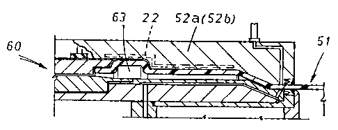
The head 66 (figures 2 and 3) comprises a die 52
which is externally associable to the pipe 51, a
buffer 55 arranged centrally to the die 52 and a
flange 60 mounted coaxially and slidably with
respect to the buffer 55 and the die 52.
The die 52 is in two parts 17 and 18, which
respectively each bear a half-die 52a, 52b.
The die 52 is further~provided with a cavity 80
for receiving a tract 50 of pipe 51, already
plasticized in the kilns 5, and exhibits an
internal surface 53 which is shaped to correspond
with the external surface 84 the finished bell
will assume.
The die 52 is further provided with conduits 54
fox a pressurized fluid, constituted by compressed
air, which conduits 54 open into the cavity 80 of
~1~s4 ~s
the internal surface 53, the function of which
will be better explained hereinafter.
The buffer 55 is removably keyed on a buffer
bearer 21 and is insertable internally to the pipe
05 51. The buffer exhibits a shaped lateral surface
81 composed of a body 57 and a front end 56, and
is finally provided with flow conduits 58 far a
pressurized fluid at the front end 56.
Sealing elements 59 are housed in special seats 70
10 on the internal surface 53 of the die 52 and on
the front end 56 of the buffer 55, and are also
situated bilaterally to the pipe 51 when the
latter is inserted between the buffer 55 and the
die 52 their purpose is to interact with the
internal and external surfaces 83, 84 of the pipe
51 so that the pipe 51 can be inserted in the head
66 under pressure-sealed conditions (figure 4).
A sealing gasket 14 is also arranged for the same
reasons at the coupling surfaces 20 where the two
parts 17, 18 of the semidies 52a, 52b couple to
each other to form the complete die 52.
The flange 60 is shaped such as to exhibit a
striker surface 82 far the pipe 51, made in an
annular cavity 61 facing and associable to an edge
62 of the pipe end tract 50.
~~~~4
11
When the buffer 55 and the die 52 are coupled, an
annular forming chamber 72 is created in the head
66, which chamber 72 is for forming the pipe end
tract 50. The peripheral limits of the forming
05 chamber 72 are defined as follows: externally, the
die 52; internally, the buffer 55; on one side the
flange 60 and on the opposite side the sealing
elements 59.
The forming chamber 72, after the buffer 55 has
been completely introduced into the pipe 51 arid
consequently the edge has contacted with the
flange 60, is subdivided by the pipe 51 into a
first and a second pressure chamber 63 and 64 for
a fluid. The first chamber 63 (see figure 4) is
I5 arrranged between the lateral surface 82 of the
buffer 55 and the internal surface 83 of the pipe
51, while the second chamber 64 is arranged
between the external surface 84 of the pipe 51 and
the internal surface 53 of the die 52.
The chambers 63, 64 are supplied by the conduits
54, 58, as will better appear from the functional
explanation of the head 66 hereinbelow, such as to
dilate and then to contract the pipe end tract 50
in order to induce a ribbing in the plastic
material of the pipe 51, pressing it first against
12
the internal surface 53 of the die 52 and then
against the external surface of the buffer 55.
Figures 1 and 3 further show how the flange 60 is
supported by a mobile ring 23 in the bell-forming
05 machine 1, the ring 23 being mobile in direction X
and comprising two concentric semiflanges 67, 68
together forming the annular cavity 61. The
semiflanges 67, 68 are slidably mounted one to the
other and are independently mobile with respect to
the die 52 and buffer 55. In particular, the more
external semiflange 67 moves in relation to the
buffer 55 and the die 52 solidly with the ring 23,
while the more internal semiflange 68 moves by
means of a pneumatic activation internally of a
guide 30 borne by the buffer 55 and provided with
sealing elements 31. Similar sealing elements 31
are placed at all possible fluid leak points about
the head 66.
Preferably a fluid outlet channel 65 from the head
66 is afforded at the annular cavity 61.
The channel 65 can be opened and closed by a
conventional solenoid valve, not shown in the
figures, piloted by the programmed control system
24 of the machine 1. Obviously the channel is
controlled according to the needs of the
13
functional cycle of the head, permitting closure
and pressurization of the first and the second
chambers (63, 64) up to when they reach
preestablished limit pressure values, at which
05 point the channel 65 is opened and the fluid
contained in the chambers 63, 64 evacuated from
the head 66.
Turning to figures 3 and 4, the internal
semiflange 68 is shaped such as to present an
inclined wall 69, diverging from the pipe 51 axis
and distancing from the pipe end tract 50 thereof,
and having the function of guiding the edge 62 of
the pipe 51 and channelling it into the annular
channel 61.
The semiflange 68 further comprises an annular
portion 85 connected to the inclined wall 69,
internally associable to the pipe 51 such as to
meet it, opposite to the pressure of the fluid
operating in the second pressurization chamber,
and providing continuity of contact with the
buffer 55.
If the pipe 51 is to be internally provided with a
throat 71 (see figure 4) for housing a sealing
gasket, the buffer 55 is internally provided with
a forming insert 73 (figure 4i) which is radially
215~~~8
14
translatable with respect to the pipe 51 fram a
first, rest position in which the insert 73 is
hidden in the buffer 55 to an operative position
in which the insert 73 exits from the buffer and
05 associates with the pipe 51 to calibrate the
required throat 71: in this case the semiflange 68
and the insert 73 are phase-synchronizedly mobile
such as to avoid mutual interference during their
reciprocal movements.
With reference to figure 4, a generalized
functional sequence of the head 66 is described.
In the initial phase (figure 4a) after the die 52
is opened, the head is neared to a plasticized
pipe end tract 50, supported projectingly from the
bench 3.
Then (figure 4b) the halfdies 52a, 52b of the die
52 are locked on the pipe 51, together with their
relative sealing elements 59 placed in direct
contact with the external surface 84 of the pipe
51. The pressurized air is sent to the forming
chamber 72 of the buffer flow conduits 58, and the
buffer 55 begins to advance, inserting into the
pipe 51. The external semiflange 67 is in its
initial position, immobile, and therefore at its
greatest distance from the pipe 51.
~1~64~~
In the phase shown in figure 4c, the buffer 55
gradually inserts into the pipe 51, producing a
first widening thereof. The internal semiflange 68
is arranged in a position of maximum advancement
05 on the buffer 55, together with which it is
inserted into the pipe 51.
During this phase the pressurized air coming from
the conduits 58 is not able to cross the sealing
element 59 arranged at the front end 56 of the
10 buffer 55 and thus flows back between the lateral
surface 81 of the buffer 55 and the internal
surface 83 of the pipe 51. It exits externally of
the head 66 through the discharge channel 65 of
the annular cavity 61, which is not closed by its
15 valve. The advanced position of the internal
semiflange 68 in relation to the buffer 55 enables
the pipe 51 to be supported continuously on the
inclined wall 69 and the annular portion 85 of the
internal semifiange 68.
In the schematized illustration in figure 4d the
internal semiflange 68 retracts such as to combine
with the external semiflange 67 to create an
annular cavity 61 of greater dimensions for
channelling the edge 62 of the bell 51 which tends
to lock on to the buffer 55 due to the elastic
16
return properties of the polyethylene.
In the phase illustrated in figure 4e the external
semiflange 67 and the internal semiflange 68
advance together towards the buffer 55 up until
05 the striker surface 82 meets with the edge of the
pipe 51 and subdivides the forming chamber 72 into
the said first and second pressure chambers 63,
64.
The phase illustrated in figure 4f shows the
discharge channel as it is closed by its own
valve, such that as air continues to exit from the
flow conduits 58 of the buffer 55 the first
pressure chamber 63 is pressurised and expands the
pipe 51 up until the external surface of the
latter meets with the internal suface of the die
52. At the same time the whole flange 60 advances
along the buffer 55 and axially contracts the pipe
51. Obviously the whole pipe is shortened in
length by the modelling of a throat 71 in the bell
for receiving a sealing gasket.
During the pressurization phase of the first
pressure chamber 63 the pipe 51, on meeting the
internal surface 53 of the die 52, undergoes a
circumferential dilatation up until its
constituent material is ribbed.
~1~~~~~
17
In the phase illustrated in figure 4g, after the
flange 60 is stopped, the pipe end tract 50
remains still for a period of time to let the
material cool, a process aided by the cooling
05 chamber 22, functioning with water and contained
in the die 52. After a further commutation of the
valve of the discharge channel 65 of the flange
60, the air contained in the first pressure
chamber 63 can freely transit once more externally
of the head 66. Thus the buffer 55 can be cooled
and can contribute further to the cooling of the
pipe end tract 50.
In the phase illustrated in figure 4h, after a
further closing of the discharge channel 65, air
feeds into the flow conduits 54 of the die 52 and
pressurizes the second pressure chamber 64:
consequently, the belled end of the pipe 51 locks
on to the buffer 55 while the internal semiflange
68 retracts in relation thereto and the pipe 51
rests on the lateral surface 81 of the buffer 55.
When the pipe 51 has been contracted on the buffer
55, it is ribbed in an opposite direction to the
ribbing of the phase illustrated in figure 4f. At
the end of this operation the second pressure
chamber 64 is discharged through the channel,
~~~~4
18
after which the buffer 55 is extracted from the
pipe 51, and the internal semiflange 68 is newly
advanced on to the buffer 55, while the external
semiflange 67 is retracted and the die 52 is
05 opened and the belied pipe 51 extracted. Then the
whole cycle is repeated for another pipe.
If it should become necessary to calibrate the
internal dimensions of the throat 71, after the
phase illustrated in figure 4g, the phase of
figure 4i may be proceeded to.
Figure 4i illustrates a phase where the buffer 55
forming insert 73 is expanded after a partial
retraction of the internal semiflange 68 and prior
to the pressurizing of the second chamber 64. Once
the latter operation has been completed, the
insert 73 reenters into the buffer 55, after
which, once the internal semiflange 68 has been
fully retracted, all the conclusive operations of
the described cycle, as in figure 4h, are
proceeded to.
In conclusion, the head 66 of the invention
permits of belling a pipe end tract 50, where the
pipe 51 is made of polyethylene, by means of a
single introduction of the pipe 51 into the head
66, thus obtaining quickly and economically a
~156~~~
19
single piece bell which will retain its proper
form over a long period of time.
05