Note : Les descriptions sont présentées dans la langue officielle dans laquelle elles ont été soumises.
~15706~
. ,.
NEW 9 O l US
BACKGROUND OF THE lNVI!... lON
This invention relates generally to coating
accessories and, more specifically, to a combination wet
coating storage container, dry coating storage container,
and package assembly for coating applicators and coating
material. For convenience of description, reference will
hereafter be made to "paint" as representative generally
of coating material.
Conventional roller painting equipment used by
consumers or professionals almost invariably consists
essentially only of a roller and a paint tray. A batch
of paint from a one gallon or other convenient sized
container of paint is poured into a paint tray which
usually has a storage capacity considerably less than the
volume of the paint container, and the roller is dipped
into the tray as the work progresses until the batch is
exhausted, at which time another batch is poured into the
paint tray. It is always hoped that the paint in the
tray will be exhausted at the same time as the person
applying the paint quits for the day or leaves the job
for an extended period of time so that a skin will not
form on the paint left in the tray due to solvent
evaporation, but quite often this does not happen. As a
consequence the user has the option of pouring the unused
paint back into the original container, which is
invariably a messy process with the potential for
spillage on a floor or carpeted surface, or leaving the
unused paint in the tray until the user can return to
finish the job. When the paint is left for even as short
a time as a few hours the solvent evaporates and an
undesirable skin forms on the surface of the paint. This
skin must then be removed before painting is resumed.
Removing the skin is an even messier task than pouring
out the unused paint with all the above described
disadvantages. In addition, due to solvent evaporation,
215706~
the now skin free paint will often be thicker than when
it was poured from the original container and, as a
consequence, the surface cover ability and quality may
consequently be lowered.
Attempts have been made to address the above
disadvantages but none to our knowledge has been
sufficiently successful to go into widespread commercial
use. For example, a number of proposals have been made
involving a mating cover for a paint tray but many, and
possibly a majority, of said proposed structures attempt
to make provision to also contain the roller in the
closed space formed by the trayed and associated cover.
Such a construction does however have inherent
disadvantages in that all, or nearly all, paint trays
include an inclined ramp near the rear thereof for the
purpose of "rolling out" or distributing a fresh roller
load of paint after dipping into the paint pool so that
the paint is evenly distributed on the roller prior to
application to a receiving surface. The surface of the
inclined ramp becomes coated with wet and sticky paint
during use and hence if the brush handle is laid thereon
preparatory to closing the cover on the tray, the
handle becomes sticky and unusable thereby requiring
cleaning prior to recommencing use. To overcome this
drawback additional structure has been proposed to hold
the handle away from the wet ramp. While such an
arrangement may be functional, the resultant structure is
impractical in that, by and large, the lid and/or tray,
and particularly the lid, may not then be manufactured by
the conventional thermoform process due to the structural
complexity of the structure. As is well-known, in the
current market environment which demands low cost
products using minimal raw material and manufacture by
conventional mass manufacturing techniques to produce a
low cost product in today's highly competitive
~ 1 5 7 ~ ~ ~
~- marketplace, such complicated structure cannot meet
current market requirements.
In addition to the foregoing requirements a paint
tray assembly consisting of a paint tray and lid must
occupy a minimal cubic space for manufacturing, shipping
and displaying purposes. Closed tray assemblies have
been proposed which are not constructed so as to contain
a roller but almost invariably they are bulky and consume
far too much space in the manufacturing, shipping and/or
displaying process to be economically feasible. The fact
that an inclined ramp is a necessity further complicates
the provision of a satisfactory tray assembly which does
not include applicator retention capacity. In fact, the
additional bulk resulting from such constructions clearly
prevents successful commercial utilization due to the
reguired low cost nature of the product, a disadvantage
which is compounded when a lid is hinged to a tray. In
effect, the trays should be nestable, the lids should be
nestable, at least with respect to one another, and a
plurality of lids should add only a minute fraction of
bulk to an egual number of trays so that manufacturing,
shipping and displaying steps may be carried out at the
lowest possible cost and least inconvenience.
It is also a requirement of a commercially practical
tray assembly that the assembly function as a package so
as to provide the option of combining the tray assembly,
either without redesign, or at least without substantial
redesign, with an appropriate paint applicator such as a
pad, so that a paint kit is formed.
,;
In addition to functioning as a paint kit the tray
assembly, whether offered to the ultimate consumer as a
tray assembly or as a paint kit, should also function as
a package. In this connection the lid should have a
wide, flat area both on its upper and lower surfaces to
~ . .
21~7060
accommodate labels and other externally applied point of
purchase marketing aids which assist in the selling
potential of the tray assembly. If the lid is made from
a clear plastic material a label on the underside of the
lid will present the product for sale and, by turning
over the lid, will provide use instructions.
SUNMARY OF THE lNv~ lON
The invention is a tray assembly composed of a paint
tray and a matching lid which, when assembled, forms a
sealed container effective to maintain paint or other
coating material in a stable condition for up to a week;
that is, for an extended period of time without a skin
forming on the paint. The tray has an inclined ramp
which blends smoothly into a paint reservoir so that
clean up of the tray at the end of a use, or in
preparation for an immediately succeeding use requiring
a different paint color, is quick and easy with no
possibility of color carry-over. The seal feature
is formed by a plurality of inwardly directed projections
on the peripheral edge of the lid so positioned that when
the lid is brought downwardly into contact with the upper
peripheral edge of the tray, the lid projections snap
under the upper rim of the tray and draw the lid into
tight sealing engagement with the tray. In addition, the
tray assembly has a supplemental locking feature
utilizing a pair of tabs which fold inwardly when
assembled to the tray to further secure the lid to the
tray.
The invention further includes a tray assembly
having the features above described in combination with
an internal applicator rest for maintaining a
supplemental applicator, such as a brush or pad, out of
contact with the main body of the tray during periods of
roller usage.
~15706~
The lid portion of the invention is adaptable for
manufacture by the thermoform process whereby minimal
material and forming costs are incurred in the
manufacturing process. In addition, the lid and tray are
so constructed that like parts nest within one another to
thereby realize maximum savings in shipping and handling
costs which further contribute to the overall economy of
manufacture.
And finally, the invention includes a flat lid
surface extending over substantially the maximum
physically available area so that labeling is
facilitated, including not only original labeling but
subsequent revisions.
Other advantageous features of the invention will
become apparent from the following description of the
invention.
BRIEF DESCRIPTION OF THE DR~WING
The invention is illustrated more or less
diagrammatically in the accompanying drawing in which:
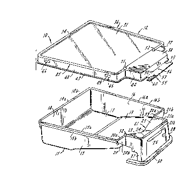
Figure 1 is an exploded view of the resealable tray
assembly of the invention;
Figure 2 is a side view of the resealable tray
assembly showing the lid in sealing engagement with the
tray;
Figure 3 is a right end view of the tray as shown in
Figure 2;
Figure 4 is a bottom plan view of the lid; and
-- 5
2157~6~
Figure 5 is a detail view showing the means for
forming sealing engagement between the lid and tray, this
Figure being shown to an enlarged scale as compared to
the other Figures.
DERCRIPTION OF A 8PECIFIC EMBODINENT
Like reference numerals will be used to refer to
like or similar parts from Figure to Figure in the
following description of the drawing.
Referring first to Figure 1 the resealable paint
tray assembly of the invention is indicated generally at
10. The tray assembly 10 includes a tray, indicated
generally at 11, and a lid, indicated generally at 12.
In Figure 1 the lid and tray are shown in an unassembled,
exploded condition whereas in Figures 2, 3 and 5 the lid
15 and tray are shown assembled.
Tray 11 includes front wall 14, left wall 15, right
wall 16 and bottom wall 17. The rear end of the tray is
composed of a number of elements including inclined ramp
19, the forward portion at least of which functions as a
portion of the bottom of the tray as well as partially
closing off the rear end. A generally vertically
disposed portion of the rear wall is indicated at 20,
said wall portion 20 flanking a brush rest section
indicated generally at 21. Brush rest section 21
includes left and right inclined sides 22, 23 which join
a flat bottom 24. The rear ends of left and right
inclined sides 22, 23 and bottom 24 terminate at rearmost
wall 25. Thus inclined walls 22, 23, bottom 24 and
rearmost wall 25 form the enclosing vertical portion of
the rear end of the tray not formed by vertical rear wall
portion 20. A pair of legs are indicated at 27, 28 which
terminate in a generally U-shaped connector 30, the legs
27, 28 and connector 30 being contoured to fit a ladder
~ 7 ~
__
tray in use in a conventional manner as will be apparent from
Figures 1 and 2.
The upper peripheral edge of front wall 14, left and right
side walls 15, 16, rear wall 20 and the uppermost edge portions
of brush rest section 21 are respectively formed by an
outwardly directed flange means having horizontal flange
portions 14a, 15a, 16a, 20a and 21a, all of which in this
instance lie in a common plane. Flange portions 14a, 15a, 16a,
20a and 21a all terminate in a downturned lip 14b, 15b, 16b,
20b and 21b respectively. It will be noted that lips 14b, 15b
and 16b extend downwardly a uniform distance which may, for
example, be on the order of about 1/8". Lips 20b and 21b
extend downwardly a substantially greater distance in order to
provide additional structural edge rigidity. It will be noted
that lip 21b, provides structural edge rigidity and also forms
a portion of the legs 27, 28. A pair of projections are
indicated at 32, 33 extending upwardly from the peripheral
flange 20a to form a stop or abutment which prevents a
paintbrush which is resting in brush rest section 21 from
sliding into the active paint reservoir formed by bottom 17,
the side walls, and inclined ramp 19.
Lid 12 includes a rectangular flat plate 31 whose edges
blend smoothly into a peripheral edge rib consisting of a front
portion, indicated generally at 34, left and right side
portions, indicated generally at 35, 36 respectively, and a
rear portion, indicated generally at 37. It will be noted that
the uppermost flat surface of the central section 38 of rear
portion 37 extends outwardly a distance sufficient to overlie
the brush rest section 21.
The contour of the front, left, right and rear portions
of the lid rib is shown best in Figure 5. The central plate
31 terminates at an upwardly and slightly outwardly inclined
boundary wall 40 which, at its upper edge, blends smoothly into
a flat wall 41, which in turn blends smoothly into downwardly
and slightly outwardly extending enclosing wall 42. Preferably
an outwardly directed lip 43 encircles the entire periphery of
the lower edge of the enclosing wall to assist the user in
grasping the lid to lift it off and place it on the tray.
As best seen in Figures 1, 4 and, particularly, 5, a
plurality of locking lugs, indicated generally at 46, are
located along the front, left and right sides of the tray lid,
preferably at least two per wall. As best seen in Figure
5 each locking lug 46 includes a generally flat upper,
trapezoidal shaped wall 47, an inner wall 48, an a downwardly
and outwardly inclined generally trapezoidally shaped bottom
wall 49. As best seen in Figure 5 the generally flat upper
wall 47 is located so as to snap under the lower edge of
lS downturned lip 15b. Preferably said wall 47 has a very slight
downward taper to assist the snap connection of locking lug 46
to lip 15b. Each of the other locking lugs is similarly
contoured. A pair of abutment housings are indicated at 51,
52 to fit over the brush abutment projections 32, 33 on tray
11.
The outwardly extending central portion 38 of the lid is
defined by a continuation 44 of downwardly and slightly
outwardly extending wall 42 as best seen in Figures 1, 2 and
3. A lid locking tab is indicated generally at 55 extending
outwardly from the wall 44 at its lower edge. Lid locking tab
55 is generally T-shaped, and consists of a wide stem section
56 and a crossbar section 57. The junction between the lower
edge of wall 44 and the base of stem portion 56 functions as
a hinge which pivots about an axis indicated at 58. The lid
locking tab 55 is
.~
2 ~
- shown in an as-molded condition in Figures 1 and 4, and
in an assembled condition in Figures 2 and 3. From
Figures 2 and 3 it will be noted that after the lid 12 is
brought down into engagement with the tray 11 and locked
and sealed thereto by the action of the locking lugs 46
snapping into the locked position of Figure 5, the end 60
of the crossbar 57 is manually bent inwardly, as viewed
in Figure 2, so that said crossbar end 60 snaps into
place behind leg 27 as best seen in Figure 3, but also in
Figure 2. End 59 is likewise snapped into a secured,
locked position behind leg 28.
From the foregoing description it will be noted that
a sealable and releasable, i.e.: a resealable, paint
tray assembly has been provided which forms a closed
container for handling raw paint for extended periods of
time, up to a week or more, without the formation of a
skin or other degradation of the paint, said sealing and
resealing functions being accomplished by the snap
engagement of the plurality of locking lugs 46 on the lid
which engage under lowermost edge of downturned lips 14b,
15b, 16b and, if desired though not shown, 20b and 21b of
the tray 11. In lieu of the use of locking lugs, the tab
connectors 59, 60 may be used at the rear end of the
tray.
By forming the lid, at least, of a clear plastic,
such as RPET, the tray assembly can be used as a
container for holding painting accessories at the point
of purchase, thereby displaying the internal components
for direct observation by the ultimate purchaser. It
should be noted that such material is recyclable, has
possibly the best solvent resistance of any of the
commercially available plastics today, and high impact
resistance as well as high tear resistance.
21S706~
The lid is resealable for the lifetime of the tray,
eliminates packaging disposal since the tray assembly
functions as a package, is reusable many times since
there are no nooks or crannies to trap paint which would
preclude re-use with a different paint color, can be used
as a dry storage container for paint brushes and sundry
items at any stage of its life cycle, provides storage
for wet roller covers and paint overnight to prevent dry
out which would otherwise occur during long periods of
nonuse between periods of use, is fully recyclable, and
permits easy label packaging changes as compared
to converting conventional packaging material. It should
also be noted that the separated inverted lid can be used
to rest wet brushes, rollers, etc. on during periods of
use since the substantial depth of the lid rib enclosing
wall 42 precludes roll-off of objects placed on the
upwardly facing inside surface of the lid. In addition
to all of the above characteristics a single lid and tray
occupy a bare minimum of space since the height of the
lid above the tray, when assembled, amounts to no more
than the thickness of the material from which the lid is
formed which may, for example, be on the order of about
.015".
Although a specific embodiment of the invention has
been illustrated and described it will be appreciated
from the foregoing description that modifications may be
made without departing from the spirit and scope of the
invention. Accordingly it is intended that the scope of
the invention be limited solely by the scope of the
hereafter appended claims when interpreted in light of
the relevant prior art, and not by limitations set out in
the foregoing specification.
-- 10 --