Note : Les descriptions sont présentées dans la langue officielle dans laquelle elles ont été soumises.
-1 ~1 57~90
"REMOT~I Y ÇONTF~OI I E~ i~EVl~E. F~R ROTATING TH~ STFFRING-
~IHE~I qF A MaTOR VE~ICL F AN~) THFiN3 T~KING IT i3ACK TO THE
STARTI~3Q P~SI~iON"
Th~ present invention conc~ms devioes for ~nalysin~ ~nd tunin~
motor vehicles, and in particular a rem~t~iy c~ntrolled devic~ for rota;irly
the ~teerin~heel ~nd then ~kin~ It i~aclc to the startin~ i~s3tion.
It is knoNn that the front steerin~ wh~els of m~tor vehlcl~ requiro a
periodi~a~ check and truin~ operation of their tos-in in order to Yerlfy the
~rr~tn~ss of the various an~les ~haraGterizln~ the forac~ e
1~ kinematic mechanism. In ~a~yin~ out said toe-in ~eratiorl, the frontwh~e~s are repeatedly ste~r~d one w~y ~nd the othsr by means of tha
steerin~-wheel, in or~er to allow also the ali~n,nent of th~ gt~erin~-wheel
spiders with the wheel~, s~ that lhe driver is nat obllsed to keep the
stserin3-wh~el li~htly f~tated on on~ sid~ to ~o str~i~ht.
1;~ This rotatlon of th~ ste~rin~-wileel is usuaily carried out manu~lly
by ffle person oar~in~ out ths t~e-in oper~tion, which blocks the st~erin~-
wheel ~n ~he deslred p~sition ~y means of a suib~le de\li~, or by an
assi~t3nt ~her~o~ which rot~te~ and bl~ck~ ths st~rln~whee! ac~ordin~ to
the ine~ructions of the operator which is undsr the ~hlcle
An e~ainple of a r~motely controlled ~pparatu~ ~ap2ble of rotatin~
the steertng wheel o~ an ~ut~mobile IR di~closed ln US-A~.465.577.
H~ver, this appar2tus i8 mainly intended tc manipulate t~e control
pedais anci th~ ~ear shift lever, white havin~ the optiona~ cap~bllity of
ro~3n~ the s~Qerin~ wheel by means ~ a pair of roll~rs h~ in~ ~ ~o~t
2s sus1'ac~ to ~ontact ~he g~eerin~ whoel rin~. It i~ apparent that this
~rran~ement ~oes n~t prevent the rol3er~ fr~m ~liding on the fin6,
partl~larly at ~h~ end of tt~e steerin~ run. Mor~ove~, It can not be applied
to steerln~ eels havin~ a shape ot~r than exa~ly circ~lar ~ . oYal o~
round~d square), otherwise ~e rollers ~ould not C~l ,ta~ the rlng proper~y
alon~ c~rtain ar~ o~ thc rotatlon.
Ths object o~ the pres~nt inventian i8 to proYide a ram~tely con~roll~d
d3vic~ o~srcQmin~ the aboYe~ited drawbacks o~ th~ prior art and suit~ble
to r~placa proper~y the operato~s a88i8tant, 55t~ that the openator
hirnself c~3n carry o;.t precise ste~rin~-wheel adju~tm~nt~ w~th n~ need
~~ CHE~
-2- 2~7~gO
to move from his workin~ p~sition.
A further object ~f th~ ~ptianed deYic~ is t~kin~ back the steerin~-
wheel ex~c~iy to the starting pos~tion at the encl ~ ~he operati~n.
The-~e o~jacts are achieYed by means of a device havin~ the
~ha~a~teri~ti~s ~ited in cl2im 1.
Theref~ra, the device acc~rdin~ to the present invsntion allows to
carry out a very flne and pracise adjustment of the steerin~-wheei
mo~em~nt, abs~lutely impossibie to ~e ac~ie~ed manually or with prior zrt
devi~es, so that the truing of the wt~63 t~e-in can b~ csrried o~t with ~reat
1 Q pr~cision.
Another adYanta~e of the captioned devic~ Is its c2pacity of
memorizing the steerin~wheel starting position and the f~liowin~
rotations thereof, so that It is c2pable of au~omatically taking back the
st~ring-whe~l exa tly to ~id position at the end o~ the operati~n.
1~ These and other advanta~es and c~aracteristics of the devic~
ac~rding t~ the present invention wiil be apparent from the followin~
detailed description cf a preferred embodiment th~reo~, reported as a non-
limitin~i example, referrin~ t~ the annexed drawin~s wher~in
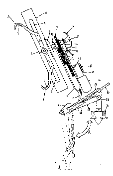
~.1 is a par~ly s~e-thro~gh ~iew of th6 captianed deYics1 wher~in
2û the mav~ment of the lower par~ion Ts indicat~d by the dotted lines;
Fiq.2 is a ~ee-~hrou~h view cf the upper p~rtic~n o~ the device
mounted on a st~in~-wh~el; and
Fi~.3 is a f~ont view of the devic~ n-Guntec on a st~erin~-wheel ~nd
wi~h the lower pQrtion in the retra ted p~siSion.
Ref~rrin~ t~ fig. 1, there is s~en that tho captianed devic~ is made up
by an upper pt~rtlcn ~r ~rippin~ the st~erin~-wh~ei, a c~ntr21 frzme
~arryin~ the drivin~ and memory apparatus and a lawer ~upp~rting
portion.
R~errin~ tc fig.2, there is shcwn that the rin~ I of the cteering-wheel
is grippe~ by m~ans of jaws 1 substantiaily hwk ~haped and internally
provided with a co~tin~ 2 suit~b~e to a~toid that said jaws 1 slip on said
ring ~ andlor scratch it. ~n the describ~d embs~diment, tt~ere ~re fou~ jaws
r ~ r`,{rl ~,
~ 94/20340 PCT/lT94/00018
3 2157~90
1 (fig.3j made of flexible steel, however they could be different in number,
position and material, as far as they continue to carry out their gripping
function on the steering-wheel.
Jaws 1 slide on an arm 3 wherein two longitudinal guides 4 are
5 formed, and the opening and closing motion of said jaws 1 is controlled by
a knob 5 which is coaxially integral with a gear 6 which engages two rack
members 7, each of which carries at one end thereof the respective jaws
1. To maintain the pressure of the latter on the ring I of the steering-
wheel, each of the members 7 is connected, at the end opposite to that of
10 jaws 1, to an end of arm 3 through a spring 8 which exerts a traction such
as to keep jaws 1 tightly gripping, and whose force must be overcome by
means of knob 5 in order to remove the device from the steering-wheel.
Turning back to fig.1, there is seen that arm 3 is connected to the
rest of the device through a plate 9 which is driven into rotation by a shaft
15 10 integral thereto which takes the motion from a gear 11 keyed thereon
and driven in turn by gears 12 for reducing and transmitting the motion
coming from a driving gear 13. This series of gears is mounted within a
central frame 14, outside which, on the lower portion thereof, a reducer 15
which operates gear 13, an electric motor 16 and a processor 17
20 controlling the operation of the device are mounted. For safety purposes,
reducer 15 includes an adjustable clutch 18 which disengages motor 16 in
case the device meets with an excessive resistance against the rotation of
the steering-wheel, so as to prevent possible damages to the device itself
and/or to the steering kinematic chain. The present device further
25 includes the means for the remote control which, in the illustrated
embodiment, consist of a radio receiver (not shown) picking up the pulses
of a radio control, but they might as well consist, in particular cases of
interferences, of a wire control.
On the upper portion of frame 14, on the outside thereof, there is
30 mounted a knob 19 coaxial with shaft 10 and provided with an internal
clutch 20 suitable to disengage said knob 19 from said shaft 10; between
the end of shaft 10 and knob 19 there is interposed a disc 21, integral with
the latter, provided with a tongue 22 which, upon rotation of said disc 21,
passes between two photocells 23 positioned below shaft 10 and
w o 94/20340 ~ T/rrg4/000l8 -
~ ~ ~3 ~ 49~ 4
connected to processor 17 which thus detects the passage of tongue 22,
said passage being also indicated by the switching on of an indicator light
24 located in front of said photocells 23.
Referring now also to fig.3, there is seen that frame 14 is connected
5 at the bottom to the device portion which provides the support to react to
the steering-wheel rotation torque.
A central structure 25, centered with respect to frame 14, contains a
battery, for operating motor 16, which is charged through proper
electrodes 26 outside the battery container; the ends of two rods are
10 pivoted on each side of structure 25, a main rod 27 in a more advanced
position and a secondary rod 28 in a more receded position towards the
steering-wheel, both of them being pivoted at the other end on a support
rod 29 which is provided at the bottom with a support plane 30, also
pivoted on said rod 29 and provided with a pair of feet 31.
For the manual operation of the supporting members, the main rod
27 extends forward into a lever 32 integral therewith, and it is provided
with an external spring 33 suitable to retain the supporting structure in the
bent position upwards and subsequently, once in the downwards rotation
indicated by arrow A the return point has been surpassed, to exert a
pressure on the support rod 29 to achieve the self-adjustment of the
support plane 30.
The operation of the device according to the present invention is now
illustrated, in particular with reference to the starting position
memorization function.
As already mentioned in the description of the device, the installation
on ring I of the steering-wheel is carried out through jaws 1 which are
opened and then closed by means of knob 5, the steering-wheel being in
any position; once jaws 1 have been properly tightened, the lower support
structure is lowered, with the aid of springs 33, by pushing on levers 32 so
that feet 31 lean on a reaction plane which, for example, is the seat
bottom or the vehicle floor, and whose inclination with respect to the
device is compensated by the self-orientation of the supporting planes 30
which are pivoted on rods 29. In case of leaning on a sinking surface such
as the seat bottom, the presence of springs 33 allows to lower feet 31
O 94120340 PCT/l'r94100018
- 5 -
~1~7~90
until the plane reacts with a force equal to that of spring 33, thus avoiding
sensible settling in the first phases of the steering-wheel rotation.
Having thus provided the device with the base required to react to
the steering-wheel reaction torque, the operator carries out the centering
5 of the steering-wheel by operating motor 16, through the remote control,
which puts into rotation arm 3 as indicated by arrow B, until he visually
finds the alignment of spiders ll of the steering-wheel. Once the steering-
wheel is exactly centered on the vertical, the operator disengages knob
19 from shaft 10 by means of clutch 20 and rotates said knob 19, carrying
10 along disc 21, until he detects, by means of indicator 24, the alignment of
tongue 22 with photocells 23; then he engages again knob 19 on shaft 10
and resets the rotation count carried out by processor 17, which, from now
on, provides the memorization of the direction and number of the
passages of tongue 22 through photocells 23.
After having carried out the setting operation of the present device,
the operator can go below the vehicle to proceed to the forecarriage
truing operation, with no further need to climb up to rotate the steering-
wheel since the remote control allows him to carry out the steering of the
wheels in the direction and for the angle required, with the possibility, for
20 example by means of two different push-buttons, of a fine or rough
adjustment of the steering angle.
At the end of the truing, the operator sends the steering-wheel re-
alignment command to processor 17, which said processor 17 carries out
by taking into account the steering-wheel position as it results from the
25 rotations it has memorized; in order to divide equally between the two
directions of rotation the unavoidable mechanical plays present in the
kinematic chain, the device does not immediately stop the steering-wheel
at the starting position, but surpasses it and then comes back surpassing
it in the opposite direction and so on, with an oscillation of decreasing
30 amplitude around said starting position. Therefore, it is apparent that the
device according to the present invention fully achieves the intended
object of replacing the additional labour presently required, with the
further advantage of a precision of rotation and of return to the starting
position impossible to be manually achieved.
WO 94/20340 PCT/IT94/00018 --
All the members of the above-described embodiment may of course
be replaced by equivalents thereof, for example a different system for
detecting and memorizing the rotations, a different motion transmission
chain, a different kind of motor, and so on.