Sélection de la langue

Search

Sommaire du brevet 2157615 

Énoncé de désistement de responsabilité concernant l'information provenant de tiers

Une partie des informations de ce site Web a été fournie par des sources externes. Le gouvernement du Canada n'assume aucune responsabilité concernant la précision, l'actualité ou la fiabilité des informations fournies par les sources externes. Les utilisateurs qui désirent employer cette information devraient consulter directement la source des informations. Le contenu fourni par les sources externes n'est pas assujetti aux exigences sur les langues officielles, la protection des renseignements personnels et l'accessibilité.

Disponibilité de l'Abrégé et des Revendications

L'apparition de différences dans le texte et l'image des Revendications et de l'Abrégé dépend du moment auquel le document est publié. Les textes des Revendications et de l'Abrégé sont affichés :

  • lorsque la demande peut être examinée par le public;
  • lorsque le brevet est émis (délivrance).
(12) Brevet: (11) CA 2157615
(54) Titre français: ENSEMBLE DE VAPORISATION SURBAISSE
(54) Titre anglais: LOW PROFILE SPRAY ASSEMBLY
Statut: Périmé et au-delà du délai pour l’annulation
Données bibliographiques
(51) Classification internationale des brevets (CIB):
  • B05B 01/14 (2006.01)
  • B05B 07/08 (2006.01)
  • B05B 07/16 (2006.01)
(72) Inventeurs :
  • FORTUNATO, FRED A. (Etats-Unis d'Amérique)
  • SHADLE, BARRY L. (Etats-Unis d'Amérique)
  • FRANZ, HELMUT (Etats-Unis d'Amérique)
(73) Titulaires :
  • PPG INDUSTRIES OHIO, INC.
(71) Demandeurs :
  • PPG INDUSTRIES OHIO, INC. (Etats-Unis d'Amérique)
(74) Agent: BORDEN LADNER GERVAIS LLP
(74) Co-agent:
(45) Délivré: 2000-11-14
(22) Date de dépôt: 1995-09-06
(41) Mise à la disponibilité du public: 1996-03-31
Requête d'examen: 1995-09-06
Licence disponible: S.O.
Cédé au domaine public: S.O.
(25) Langue des documents déposés: Anglais

Traité de coopération en matière de brevets (PCT): Non

(30) Données de priorité de la demande:
Numéro de la demande Pays / territoire Date
316,148 (Etats-Unis d'Amérique) 1994-09-30

Abrégés

Abrégé anglais


The present invention provides a multiple nozzle liquid spray
assembly having a longitudinally extending bar member, receivers to allow
securing of nozzles along the bar, a coolant conduit extending along at
least a portion of the bar, liquid and gas conduits extending along the bar
in close proximity to each of the receivers, and first and second sets of
passages interconnecting each of the receivers with the liquid or gas
conduits. In one particular embodiment of the invention, the coolant
conduit includes a first portion which extends from a coolant inlet along a
first longitudinal side of the bar member and a second portion which
extends from a coolant outlet along an opposing longitudinal side of the
bar member. The liquid conduit and gas conduit generally parallel each
other and extend along the bar member between the first and second
portions of the cooling conduit.

Revendications

Note : Les revendications sont présentées dans la langue officielle dans laquelle elles ont été soumises.


CLAIMS
1. A multiple nozzle liquid spray assembly comprising:
a longitudinally extending bar member;
receivers spaced along said bar member to allow securing of nozzles
along said bar member;
nozzles secured to said receivers;
a coolant conduit extending along at least a portion of said bar
member;
at least one liquid conduit extending along said bar member proximate
to each of said receivers;
at least one gas conduit extending along said bar member proximate to
each of said receivers;
a first set of passages interconnecting each of said receivers with said
at least one liquid conduit; and
a second set of passages to interconnect each of said receivers with
said at least one gas conduit, wherein said passages and at least a portion of
each
of said coolant, liquid and gas conduits are formed by said bar member.
2. A multiple nozzle liquid spray assembly comprising:
a longitudinally extending bar member;
receivers spaced along a surface of said bar member to allow securing
of nozzles to said bar member;
nozzles secured to said receivers;
a coolant conduit extending along at least a portion of said bar
member;
a liquid conduit extending along said bar member proximate to each of
said receivers;
a gas conduit extending along said bar member proximate to each of
said receivers;
a first set of passages interconnecting each of said receivers with said
liquid conduit; and

a second set of passages interconnecting said gas conduit with said
bar member surface, wherein said second set of passages extends to said
surface
proximate to said receivers.
3. The spray assembly as in claim 2 wherein said coolant conduit, said
liquid conduit and said gas conduit are located within said bar member.
4. The spray assembly as in claim 2 wherein said coolant conduit, said
liquid conduit and said gas conduit are a coolant channel, a liquid channel
and a gas
channel, respectively, extending along at least one surface of said bar member
and
further including plate members to seal each of said channels to form said
respective conduits.
5. The spray assembly as in claim 2 further including a coolant inlet
and coolant outlet, wherein said coolant conduit includes a first portion
extending
from said coolant inlet and positioned along a first longitudinal side of said
bar
member and a second portion extending from said coolant outlet and positioned
along an opposing longitudinal side of said bar member.
6. The spray assembly as in claim 5 wherein said liquid conduit and
gas conduit extend along said bar member between said first and second
portions of
said coolant conduit.
7. The spray assembly as in claim 2 wherein said liquid and gas
conduits are parallel to each other along said bar member.
8. The spray assembly as in claim 2 wherein said receivers are a first
set of receivers for a first row of nozzles and said liquid conduit is a first
liquid
conduit positioned proximate to said first set of receivers and further
including a
second set of receivers along said bar member surface to allow securing of a
second row of nozzles to said bar member, a second liquid conduit extending
along
said bar member proximate to said second set of receivers, a third set of
passages

of receivers, and a fourth set of passages interconnecting said gas conduit
with
said bar member surface, wherein said fourth set of passages extends to said
bar
member surface proximate to said second set of receivers.
9. The spray assembly as in claim 2 wherein said receivers are a
first set of receivers for a first row of nozzles and said gas conduit is a
first gas
conduit positioned proximate to said first set of receivers and further
including a
second set of receivers along said bar member surface to allow securing of a
second row of nozzles to said bar member, a second gas conduit extending along
said bar member proximate to said second set of receivers, a third set of
passages interconnecting said second gas conduit with said bar member surface,
wherein said third set of passages extends to said bar member surface
proximate
to said second set of receivers, and a fourth set of passages interconnecting
said
liquid conduit with said second set of receivers.
10. The spray assembly as in claim 2 wherein said liquid conduit
includes at least one liquid inlet and said gas conduit includes at least one
gas
inlet.
11. The spray assembly as in claim 8 wherein said liquid and gas
conduits are parallel to each other along said bar member.
12. The spray assembly as in claim 9 wherein said liquid and gas
conduits are parallel to each other along said bar member.
13. The spray assembly as in claim 2, further including means to
distribute gas along said bar member surface in the vicinity of said
receivers.
14. The spray assembly as in claim 13 wherein said distributing
means includes a groove along said bar member surface surrounding at least a
portion of said receivers.

15. The spray assembly as in claim 2 wherein said first and second
sets of passages and at least a portion of each of said coolant, liquid and
gas
conduits are formed by said bar member.
16. The spray assembly as in claim 5 wherein said gas conduit is
adjacent said liquid conduit and said first portion of said coolant conduit,
said
liquid conduit is adjacent said gas conduit and said second portion of said
coolant
conduit, and said first portion of said coolant conduit is adjacent to said
second
portion of said coolant conduit.
17. A multiple nozzle spray assembly comprising:
an elongated housing;
a plurality of nozzles mounted in spaced relation along a surface of
said housing;
a coolant conduit extending within at least a portion of said housing;
a liquid conduit extending within said housing proximate to said
nozzles;
a first set of passages extending through and formed by said housing
to interconnect said liquid conduit with each of said nozzles;
a gas conduit extending within said housing proximate to said
nozzles; and
a second set of passages extending through and formed by said
housing to interconnect said gas conduit with each of said nozzles.
18. The spray assembly as in claim 17 wherein said coolant conduit,
said liquid conduit and said gas conduit are a coolant channel, a liquid
channel
and a gas channel, respectively, extending along surfaces of said housing and
further including plate members to seal each of said channels to form said
respective conduits.
19. A multiple nozzle liquid spray assembly comprising:
a longitudinally extending bar member with a first section having a
first coolant channel, a first liquid channel and a first gas channel
extending along

a first surface of said first section, and a second section having a second
coolant
channel, a second liquid channel and a second gas channel positioned extending
along a first surface of said second section, a gasket positioned between said
first
and second sections, and means to join said first and second sections
together,
wherein said first and second coolant channels form a coolant conduit, said
first
and second liquid channels form a liquid conduit and said first and second gas
channels form a gas conduit;
nozzle receivers positioned along a second surface of said first
section of said bar member proximate to said liquid and gas conduits;
nozzles secured to said receivers;
a first set of passages interconnecting each one of said receivers
with said liquid conduit; and
a second set of passages interconnecting said gas conduit with said
second surface, wherein said second passages extend to said second surface
proximate to said nozzle receivers.

Description

Note : Les descriptions sont présentées dans la langue officielle dans laquelle elles ont été soumises.


2157615
- 1-
This invention relates to a liquid spray system and in
particular to a low profile spray system that may be used in a high
temperature environment.
In multiple nozzle spray systems, piping arrangements are
used to deliver the liquid to be sprayed and an atomizing gas to each of
the nozzles. In high temperature applications, e.g. when the nozzle
arrangement is used to spray a coating on a hot glass or ribbon, the
arrangement must be cooled in order to maintain the structural integrity of
the system and to prevent premature volatilization of the liquid to be
sprayed prior to it reaching the nozzles. In addition, oftentimes the nozzle
arrangement must be used in areas having limited space for locating the
spray system.
It would be advantageous to provide a low profile spray
arrangement that may be used in high temperature applications.
Summary of the Invention
The present invention provides a multiple nozzle liquid spray
assembly having a longitudinally extending bar member, receivers to allow
securing of nozzles along the bar, a coolant conduit extending along at
least a portion of the bar, liquid and gas conduits extending along the bar
in close proximity to each of the receivers, and first and second sets of
passages interconnecting each of the receivers with the liquid or gas
conduits. In one particular embodiment of the invention, the coolant
conduit includes a first portion which extends from a coolant inlet along a
first longitudinal side of the bar member and a second portion which

z1~7s1~
-2-
extends from a coolant outlet along an opposing longitudinal side of the
bar member. The liquid conduit and gas conduit generally parallel each
other and extend along the bar member between the first and second
portions of the cooling conduit.
Description of the Drawings
Figure 1 is a plan view of a multiple nozzle spray
arrangement disclosed in the present invention, with portions removed for
clarity.
Figure 2 is an elevational side view of the spray arrangement
illustrated in Figure 1 .
Figure 3 is an end view of the spray arrangement of Figure 1.
Figure 4 is a cross-sectional view taken along line 4-4 of
Figure 1.
Figures 5 and 6 are a cross-sectional views similar to that
shown in Figure 4 of alternate spray arrangements.
Figure 7 is a plan view similar to that shown in Figure 1 of an
alternate spray arrangement, with portions removed for clarity.
Figure 8 is a cross-sectional view taken along line 8-8 of
Figure 7.
Figure 9 is a plan view similar to that shown in Figure 1 of
another alternate spray arrangement, with portions removed for clarity.
Figure 10 is a cross-sectional view taken along line 10-10 of
Figure 9.
detailed Descriation of the Invention
Figure 1 illustrates a low profile, multiple nozzle spray
arrangement of the present invention which may be used to apply a

2157615
-3-
coating to a substrate. For example, the arrangement may be used to
apply a solar reflective coating on a glass surface or coat the lower
surface of a hot glass sheet or ribbon to protect against roll marking
during handlin5. The spray arrangement includes a manifold 10 which
S directs the material to be sprayed and an atomizing gas to a set of nozzles
positioned along the manifold 10, as will be discussed later in more detail.
When the manifold is used in a high temperature environment, it must be
cooled to prevent volatilization of the spray material within the manifold
prior to it being sprayed and further to prevent the manifold 10 from
10 warping.
In the particular embodiment illustrated in Figures 1-4,
manifold 10 includes a bar member 12 with cooling conduit 14 extending
from surface 16 through most of bar 12's thickness, and generally
extending about the bar's periphery. Coolant inlet 18 and outlet 20 are
connected to opposite ends of conduit 14. Bar 12 also includes a liquid
conduit 22 and a gas conduit 26 positioned along surface 30 of bar 12.
Inlets 24 and 28 are located at one end of conduits 22 and 26,
respectively, to supply liquid and gas to the manifold 10. Plugs 32 and
34 are positioned at the other end of conduits 22 and 26, respectively, to
assist in cleaning out the manifold 10, and if required, provide additional
inlets for connection to additional liquid and gas supply lines /not shown)
to equalize pressure along these conduits. Although not required, coolant
inlet 18, coolant outlet 20, liquid inlet 24 and gas inlet 28 are positioned
along the lateral sides of the bar 12 as shown in Figure 1. It should be
further appreciated that although the cooling, liquid and gas conduits of
the particular low profile spray configuration illustrated in Figures 1-4 are
on opposite sides of the bar 12, as an alternative the conduits may all be
located along the same side of the bar member 12. Conduits 22 and 26

2157615
-4-
generally parallel each other and extend the length of bar 12 between
portions of coolant conduit 14. Nozzles 36 are secured to bar 12 in any
convenient manner at predetermined spacings. Spray material is supplied
from conduit 22 to nozzles 36 through ports 38 and pressurized gas is
supplied from conduit 26 to nozzles 36 through ports 40. Plate 42 seals
conduit 14 and plates 44 and 46 seal conduits 22 and 26, respectively. It
should be appreciated that the conduits may be formed within the bar
member 12 so that sealing plates would not be required.
In one particular embodiment of the invention, bar 12 was
constructed from a stainless steel bar 2 inches (5.08 cm) wide by 1 inch
(2.54 cm) thick. Plates 42, 44 and 46 are 0.125 inch (0.318 cm) thick
stainless steel. Sealed conduit 14 is approximately 0.375 inches wide by
0.75 inches deep (0.953 by 1.91 cm) and sealed conduits 22 and 26 are
approximately 0.25 inches wide by 0.375 inches deep (0.635 by
0.953 cm).
A variety of different types of nozzle 36 having different
configurations and spray patterns as is well known in the art may be used
in combination with the manifold 10 illustrated in Figures 1-4. In one
particular embodiment of the invention where the manifold 10 was used
to spray material on the lower surface of a hot glass ribbon to reduce roll
marking, the nozzles 36 were air atomizing, flat spray, external mix
nozzles available from Spraying Systems Company, Illinois, and in
particular type no. SUE 18B nozzles. With this particular nozzle
configuration, referring to Figures 3 and 4, the ports 38 direct the spray
material from liquid conduit 22 into nozzle receivers 48 (only one shown
in Figure 4), each of which receives a nozzle 36 (shown in Figure 3). In
addition, ports 40 direct the atomizing gas from conduit 26 into a circular

2157615
-S-
groove 50 around each receiver 48 along surface 16 to better distribute
the atomizing gas to this particular nozzle 36 configuration.
In using the spray arrangement illustrated in Figures 1-4 to
apply a coating to a substrate S, the spacing of the nozzles along bar 12
and positioning of the manifold 10 relative to the substrate surface may
be such that there is an overlap of the area sprayed by the nozzles 36 to
ensure adequate coverage, as shown in Figure 2.
Figure 5 illustrates an alternate embodiment of the invention
wherein bar member 1 12 is divided into an upper section 1 12A and lower
section 1 12B, with portions of cooling conduit 1 14, liquid conduit 122
and gas conduit 126 extending along opposing faces of sections 1 12A
and 1 12B. When sections 1 12A and 1 12B are joined together by bolts
(not shown) or another joining means, as is well know in the art, the
conduits 1 14, 122 and 126 are formed. A gasket 100 may be positioned
between sections 1 12A and 1 12 B to seal the spray assembly and
prevent leakage.
Figure 6 illustrates another embodiment of the invention
wherein the conduits are aligned in two rows within manifold 210. More
particularly, liquid conduit 222 extends along surface 216 of bar 212 and
gas conduit 226 extends along surface 230. Cooling conduit 214 is
positioned below the liquid conduit 222 and extends along surface 216,
around one end (not shown) of the manifold 210 and back along surface
230 below gas conduit 226. Plates 242, 244, and 246 seal conduits
214, 222 and 226, respectively.
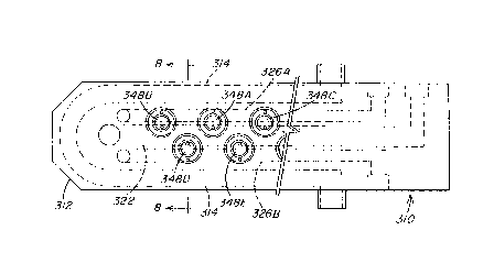
Figures 7 and 8 illustrate an alternate embodiment of the
invention which incorporates two rows of nozzles. Manifold 310 includes
a cooling conduit 314 extending about the periphery of bar 312. Gas
conduits 326A and 326B extend along the length of the bar 312 between

2157615
-6-
portions of cooling conduit 314. Liquid conduit 322 extends generally
along the center of the bar 312 between gas conduits 326A and 326B.
Although limited in the present invention, the two rows of receivers 348
shown in Figure 7 which receive two sets of nozzles 336 (only one nozzle
shown in Figure 8), are positioned along manifold 310 in a staggered
orientation. With this arrangement, depending on the nozzle spacing and
the shape of the spray configuration, the spray from each nozzle may be
overlapped by the sprays from up to four adjacent nozzles. More
particularly, if the nozzles 336 have a conical spray distribution, the spray
from nozzle at receiver 348A will be overlapped by the corresponding
sprays from nozzles at receivers 348B, 348C, 348D and 348E. Such a
nozzle arrangement may be used to ensure adequate coverage of the
substrate by the spray. Bar 312 also includes ports, in a manner similar
to that discussed earlier, to deliver the liquid from conduit 322 and gas
from conduits 326A and 326B to the nozzles 336. It should be appreciated
that additional rows of nozzles may be added to the manifold 310, with
the liquid and gas being supplied to adjacent rows of nozzles by common
conduits, in a manner as described above. It should be further
appreciated that depending on the nozzle configuration, the embodiment
of the invention illustrated in Figures 7 and 8 may be modified so that
there are two gas conduits and a single common liquid conduit. As an
alternative to using multiple gas and/or liquid conduits, a multiple row
nozzle arrangement as shown in Figure 7 may include a single liquid and
gas conduit which generally paralleling each other and extend in a
serpentine configuration to deliver liquid and gas to each nozzle on the
manifold 310.
Figures 9 and 10 illustrate another embodiment of the
present invention. Manifold 410 includes a liquid conduit 422, which

215761
_,_
includes an inlet 424 and extends through cooling pipe 414A, and a gas
conduit 426, which includes an inlet 428 and extends through cooling
pipe 414B. Pipes 414A and 414B are secured together along their length
with opening 450 located at one end of the manifold 410 interconnecting
the pipes so that coolant may enter the manifold 410 through coolant
inlet 418, pass through pipe 414B, opening 450 and pipe 414A, and exit
the manifold 410 through coolant outlet 420. A plurality of ducts 438
extend from liquid conduit 422 to above pipe 414A and a plurality of
ducts 440 extend from gas conduit 426 to above pipe 414B. Each pair of
ducts 438 and 440 connect the liquid and gas conduits to a nozzle
assembly which includes a nozzle 436 secured to a receiver 448, in any
convenient manner, e.g. compression fittings 452 and 454. In one
particular embodiment of the invention, the receiver 448 is a model
1 /4JBC back connect and nozzle 436 is an external mix, flat spray nozzle
model SUE 18B, both available from Spraying Systems Company.
The invention described and illustrated herein represents a
description of illustrative preferred embodiments thereof. It is understood
that various changes may be made without departing from the gist of the
invention defined in the claims set to follow.

Dessin représentatif
Une figure unique qui représente un dessin illustrant l'invention.
États administratifs

2024-08-01 : Dans le cadre de la transition vers les Brevets de nouvelle génération (BNG), la base de données sur les brevets canadiens (BDBC) contient désormais un Historique d'événement plus détaillé, qui reproduit le Journal des événements de notre nouvelle solution interne.

Veuillez noter que les événements débutant par « Inactive : » se réfèrent à des événements qui ne sont plus utilisés dans notre nouvelle solution interne.

Pour une meilleure compréhension de l'état de la demande ou brevet qui figure sur cette page, la rubrique Mise en garde , et les descriptions de Brevet , Historique d'événement , Taxes périodiques et Historique des paiements devraient être consultées.

Historique d'événement

Description Date
Inactive : CIB de MCD 2006-03-11
Le délai pour l'annulation est expiré 2002-09-06
Lettre envoyée 2001-09-06
Accordé par délivrance 2000-11-14
Inactive : Page couverture publiée 2000-11-13
Inactive : Taxe finale reçue 2000-07-20
Préoctroi 2000-07-20
Lettre envoyée 2000-06-07
Un avis d'acceptation est envoyé 2000-06-07
Inactive : Dem. traitée sur TS dès date d'ent. journal 2000-05-30
Inactive : Renseign. sur l'état - Complets dès date d'ent. journ. 2000-05-30
Inactive : Approuvée aux fins d'acceptation (AFA) 2000-05-11
Lettre envoyée 1999-08-05
Demande publiée (accessible au public) 1996-03-31
Toutes les exigences pour l'examen - jugée conforme 1995-09-06
Exigences pour une requête d'examen - jugée conforme 1995-09-06

Historique d'abandonnement

Il n'y a pas d'historique d'abandonnement

Taxes périodiques

Le dernier paiement a été reçu le 2000-08-23

Avis : Si le paiement en totalité n'a pas été reçu au plus tard à la date indiquée, une taxe supplémentaire peut être imposée, soit une des taxes suivantes :

  • taxe de rétablissement ;
  • taxe pour paiement en souffrance ; ou
  • taxe additionnelle pour le renversement d'une péremption réputée.

Les taxes sur les brevets sont ajustées au 1er janvier de chaque année. Les montants ci-dessus sont les montants actuels s'ils sont reçus au plus tard le 31 décembre de l'année en cours.
Veuillez vous référer à la page web des taxes sur les brevets de l'OPIC pour voir tous les montants actuels des taxes.

Historique des taxes

Type de taxes Anniversaire Échéance Date payée
TM (demande, 2e anniv.) - générale 02 1997-09-08 1997-08-20
TM (demande, 3e anniv.) - générale 03 1998-09-08 1998-08-18
Enregistrement d'un document 1999-06-28
TM (demande, 4e anniv.) - générale 04 1999-09-06 1999-08-20
Taxe finale - générale 2000-07-20
TM (demande, 5e anniv.) - générale 05 2000-09-06 2000-08-23
Titulaires au dossier

Les titulaires actuels et antérieures au dossier sont affichés en ordre alphabétique.

Titulaires actuels au dossier
PPG INDUSTRIES OHIO, INC.
Titulaires antérieures au dossier
BARRY L. SHADLE
FRED A. FORTUNATO
HELMUT FRANZ
Les propriétaires antérieurs qui ne figurent pas dans la liste des « Propriétaires au dossier » apparaîtront dans d'autres documents au dossier.
Documents

Pour visionner les fichiers sélectionnés, entrer le code reCAPTCHA :


Pour visualiser une image, cliquer sur un lien dans la colonne description du document. Pour télécharger l'image (les images), cliquer l'une ou plusieurs cases à cocher dans la première colonne et ensuite cliquer sur le bouton "Télécharger sélection en format PDF (archive Zip)" ou le bouton "Télécharger sélection (en un fichier PDF fusionné)".

Liste des documents de brevet publiés et non publiés sur la BDBC .

Si vous avez des difficultés à accéder au contenu, veuillez communiquer avec le Centre de services à la clientèle au 1-866-997-1936, ou envoyer un courriel au Centre de service à la clientèle de l'OPIC.


Description du
Document 
Date
(aaaa-mm-jj) 
Nombre de pages   Taille de l'image (Ko) 
Dessins 2000-05-09 4 96
Revendications 2000-05-09 5 191
Description 2000-05-09 7 279
Abrégé 1996-03-30 1 21
Description 1996-03-30 7 265
Revendications 1996-03-30 5 198
Dessins 1996-03-30 5 93
Dessin représentatif 1997-12-28 1 12
Dessin représentatif 2000-10-17 1 9
Avis du commissaire - Demande jugée acceptable 2000-06-06 1 162
Avis concernant la taxe de maintien 2001-10-03 1 179
Correspondance 2000-07-19 1 26
Correspondance de la poursuite 1999-04-27 2 56
Correspondance de la poursuite 1997-08-26 12 524
Demande de l'examinateur 1999-02-01 2 51
Demande de l'examinateur 1997-05-29 4 197
Correspondance de la poursuite 1996-04-01 12 419