Note : Les descriptions sont présentées dans la langue officielle dans laquelle elles ont été soumises.
2~:~'~~ ~'~
MICROWAVE DEVICE AND METHOD
FOR MEASURING MULTIPHASE FLOWS
The present invention relates to a method and apparatus for making
measurements in
multiphase flows using microwave techniques. In particular, the invention
provides a
method and apparatus for measuring volume fractions of phases in multiphase
flows such
as are typically encountered in producing hydrocarbon wells.
When multiphase fluids flow in a conduit such as a pipe, the distribution of
the phases is
generally irregular or non-uniform in the conduit, especially where the
conduit is deviated
from vertical. Often one phase is flowing at a faster rate than the others.
This is
particularly the case where there is a gas phase and a liquid phase or when
there is a
continuous liquid phase with an immiscible liquid phase of different density
dispersed
therein. Consequently, it is desirable to know the volume fraction of each
phase in the
flow and the distribution of the phases in the conduit.
Various approaches have been proposed to measure volume fraction and phase
distribution
in multiphase flows. It is generally considered preferable that the
measurement technique
be non-invasive, i.e., that any sensors should be placed at the periphery of
the conduit
rather than being positioned in the flow itself. In cases such as flows from
hydrocarbon
wells, in which there is a conductive phase (water or brine) and a non-
conductive phase (oil
and/or gas), it has been proposed to use capacitive measurements to analyze
the flow.
U.S. 5,017,879 describes an arrangement in which electrodes are arranged
around a pipe
to measure the capacitance of the fluid as it flows past the electrodes. U.S.
5,291,791
describes a development of the technique described in U.S. 5,017,879 in which
a series of
electrodes are arranged around the pipe and are connected to a switching
arrangement
which controls the function of each electrode. By controlling the switching
arrangement so
as to create a measurement configuration similar to that in U.S. 5,017,879,
and
continuously changing the switching arrangement, the configuration effectively
rotates
around the pipe. The measurements taken for each position of the configuration
can then
be integrated over a given number of rotations to average out variations in
sensitivity of the
basic configuration due to the distribution of the phases in the pipe. U.S.
4,074,184
proposes a somewhat different approach, again using a series of electrodes
around the pipe
and a switching arrangement. In this case, each electrode in turn is excited
and the
capacitance is measured at each of the remaining electrodes. The measurements
are then
integrated over a given number of "rotations" to determine the volume fraction
of the
phases.
~l~'~u~~~
-2-
Capacitive techniques using a series of electrodes around a pipe have also
been proposed
for tomographic flow imaging techniques in order to identify the distribution
of phases
within the pipe.. Examples of these can be found in U.S. 5,130,661 and GB
2,223,850.
Insertion devices using microwave propagation have been proposed for measuring
volume
fractions in multiphase flows, for example in U.S. 5,101,163, U.S. 4,996,490
and GB
2,2262,807. However, these techniques are not applicable to non-invasive
devices. An
imaging system for active microwave tomography is proposed in "Cylindrical
Geometry:
A Further Step in Active Microwave Tomography", IEEE Transactions on Microwave
Theory and Techniques, Vol. 39, No. 5, May 1991. In this system, a cylindrical
arrangement of microwave antennae is described, the object to be imaged being
positioned
inside this arrangement. Each antenna in turn transmits microwave energy which
is
detected at the remaining antennas. An image of the object is reconstructed
from the
detected signals. There is no teaching in this document which relates to
dynamic
measurements such as those in flowing fluids.
The present invention seeks to provide a method and apparatus which can be
used to
measure multiphase flows such as those encountered from hydrocarbon producing
wells.
In one aspect, the present invention provides a method for measuring
multiphase flows in a
conduit using series of microwave antennae arranged around the circumference
of the
conduit so as to transmit microwave energy into, or detect propagated
microwave energy in
the conduit, the method comprising: transmitting microwave energy from each
antenna in
turn while detecting microwave energy at the non-transmitting antenna and
integrating the
results from all antennae so as to characterize the flow in the conduit.
Preferably each antenna comprises a cross dipole antenna pair, typically with
one dipole
aligned with the axis of the conduit (the general direction of flow) and the
other dipole
aligned with the circumference of the conduit (perpendicular to both the axial
direction and
the radial direction). In this case each dipole of each pair is used in turn
to transmit, and the
corresponding dipoles in the other pairs are used to receive microwave energy.
The
antennae can be arranged in a generally planar array around the circumference
of the
conduit or can be spaced axially along the conduit from each other as well as
circumferentially, e.g., a helical array.
CA 02157637 2004-10-15
69897-30
3
The microwave energy can be transmitted at one or more
frequencies for each antenna or dipole, the frequencies
being selected according to the general type of flow
encountered in the pipe so as to optimize the response of
the technique to the flow.
In another aspect, the invention provides an apparatus for
measuring multiphase flows comprising: a series of microwave
antennae arranged around a flow conduit, means for exciting
each antenna to turn to transmit microwave energy into the
pipe and for detecting microwave energy at the non-
transmitting antennae, and means for integrating the results
from all transmitters to characterize the flow in the
conduit.
In a further aspect, there is provided a method for
measuring multiphase flows in a conduit comprising using
series of microwave antennae arranged around the conduit,
each antenna being capable of transmitting microwave energy
into the conduit and detecting propagated microwave energy
in the conduit, transmitting microwave energy from each
antenna in turn while detecting said microwave energy at
antennae which are not transmitting after propagation in the
conduit so as to generate output signals; and integrating
the output signals from all antennae so as to measure the
flow in the conduit.
In another aspect, there is provided apparatus for measuring
multiphase fluid flows comprising: a flow conduit through
which said multiphase fluid flows, a series of microwave
antennae arranged around the flow conduit, means for
exciting each antenna in turn to transmit microwave energy
into the conduit, means for detecting microwave energy
propagated in the conduit at the antennae which are
CA 02157637 2004-10-15
69897-30
3a
not transmitting and for producing output signals, and means
for integrating the output signals from all antennae to
measure flow in the conduit.
The means for exciting each antenna can comprise a signal
source and a switching arrangement for connecting the signal
source to each antenna in turn while connecting the
remaining antennae to a detector.
The present invention will now be described with reference
to the accompanying drawings, in which:
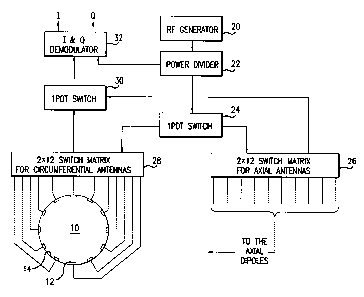
Figure 1 shows a schematic diagram of an apparatus according
to one embodiment of the invention;
Figure 2 shows a microwave antenna for use in the present
invention;
Figures 3a and 3b show the reconstruction of the
permittivity E and conductivity s/m in a pipe using
calculated data from the circumferential dipole only;
Figures 4a and 4b show the reconstruction of the
permittivity E an conductivity s/m in a pipe using
calculated data from the axial dipole only; and
Figures 5a and 5b show the reconstruction of the
permittivity E and conductivity s/m in a pipe using both
circumferential and axial measurements.
Figure 1 shows a system according to the present invention
for measuring the volume fraction of the phase in flow from
a hydrocarbon well. The system comprises a pipe 10 through
which the fluids flow, and a series of microwave antennae 12
mounted in the wall of the pipe 10 with radiating faces
flush with the inner surface 14 of the pipe 10. In this
case twelve antennae are shown although this number can be
CA 02157637 2004-10-15
69897-30
3b
varied according to requirements. Each antenna 12
preferably comprises a crossed-dipole, cavity backed slot
antenna of the type shown in Figure 2 and described in
U.S. 5,243,290 which discloses such antennae for use in
logging underground formations. Figure 2 shows a
perspective view of a cross-dipole antenna 40 for use in
this invention. The antenna 40 is a slot antenna having a
square aperture 42. In the preferred embodiment, the
antenna 40 operates
-4-
in the range of 100 to 2000 MHz and the antenna aperture is 0.334" on each
side. The
antenna 40 has two perpendicular probe elements 44 (dipoles) which are
centered in the
aperture. Each probe element 44 is 0.063" diameter at its opposite ends. The
center of
each probe is narrow so the probes do not contact one another. Antennas of
other
dmensions are possible. These particular dimensions are one example and were
chosen to
yield an antenna having reasonable signal strength and acceptable resolution
for borehole
applications. The elements 44 could be off centered, if desired. The antennae
are arranged
such that one dipole is aligned with the pipe axis so as to couple with the TE
modes of the
cylindrical waveguide (pipe) and the other is aligned in a circumferential
direction so as to
couple with the TM modes such that the antenna can radiate in two orthogonal
directions.
Each dipole can be operated independently to transmit or receive microwave
energy. In an
alternative case, both magnetic dipoles are excited simultaneously to focus
the radiation.
Choice of an appropriate phase and/or amplitude relationship allows the beam
to be steered
in a desired direction which is equivalent to exciting a combination of both
TE and TM
modes simultaneously which might be advantageous in certain circumstances.
The system for operating the antennae comprises an RF signal generator 20
which can
output signals typically in the range 100-2000 MHz. The frequency is selected
to avoid
wave propagation along the pipe which means that for a 4" diameter pipe filled
with oil
and/or gas, i.e. a lossless fluid, the frequency should be less than 1400 MHz.
When the
pipe is filled with a lossy fluid attenuation of the wave means that operating
below the
cutoff provides little advantage and other advantages can be obtained by
working at higher
frequencies with cavity-backed slot antennae. In this case it has been found
that an
operating frequency in the range 500-1000 MHz ensures high antenna efficiency
and
operation below cutoff in lossless fluids. It is particularly preferred that
the signal generator
provides a number of signal frequencies, for example, two signals of different
frequency
can be used for a given measurement. The frequency or frequencies used can be
determined by identifying the general type of flow encountered and by simple
experimentation. The output from the signal generator is fed to a power
divider 22. The
power divider 22 feeds the signal, by way of a switch 24, to either of a pair
of switching
matrices 26, 28. One of the switching matrices 26 is associated with the axial
dipoles of
the antennae 12 and the other 28 is associated with the circumferential
dipoles. The
switching matrices are configured such that the RF signal is applied to each
antenna 12 in
turn while the remaining antennae receive transmitted microwave energy and
output a
signal. The output signals from the non-transmitting antennae are fed, via a
further switch
30 which is set to correspond to the setting of the first switch 24, to a
demodulator 32
~~~~~J~
-5-
which also receives a signal input from the power divider 22, i.e., a homodyne
system. It
is also possible to use a heterodyne detection system if desired. The
demodulator 32
outputs signals indicative of the in-phase and quadrature signals detected at
each antenna.
The in-phase and quadrature signals are used to determine the amplitude ratios
and the
phase shift of the detected signals with respect to the transmitted signals.
The amplitude
ratios (attenuation) and phase shifts are analyzed to determine the volume
fraction of the
phases in the pipe.
In the general case, the system comprises N antennae, one of which transmits
and N -1
act as receivers measuring N -1 amplitudes and N -1 phase shifts with respect
to the
transmitter. This constitutes 2~N(N-1) l 2~ = N(N-1) independent propagation
measurements, each sampling a different region of the pipe cross section. This
number is
doubled where crossed dipole antennae are used and where more than one
frequency is
used. The data obtained from these measurements is used to reconstruct the
spatial
distribution of the dielectric constant and conductivity of the flowing
mixture over the
' cross-section of the pipe and hence the distribution of phases in the pipe.
This can be done
a
by tomographic techniques such as back propagation methods or by iterative
inversion
techniques such as those based on a Newton-type minimization approach.
In use, the switches and switching matrices are first set such that a RF
signal is applied to
one set of antenna dipoles, for example the axial dipoles. The associated
switching matrix
operates to apply the signal to the axial dipole of each antenna in turn while
switching the
axial dipoles of the remaining antennae to receive microwave energy which is
output as a
series of signals to the demodulator and analyzer. If more than one frequency
is to be used,
the different frequencies are applied sequentially to each antenna. Once each
axial dipole
has been used to transmit microwave energy into the pipe the switches are
reset such that
the circumferential dipoles are excited and the measurement sequence is
repeated for each
antenna as before. The outcome of this sequence is that a series of signals
will be generated
which correspond to a measurement at one or more frequencies for each dipole
of each
antenna measured at the corresponding dipole of each of the other antennae.
The series of
signals can then be analyzed using an inversion algorithm so as to determine
the volume
fraction of oil in the pipe at a given instant. This is demonstrated below in
an example in
which the signal output of a typical apparatus for a given situation is
calculated and the
output analyzed to give the oil volume fraction.
~~~~~j~
-6-
This example utilizes a forward model which enables one to predict the
response of the
apparatus, for a given known permittivity and conductivity map (i.e. oil and
water
distribution within the pipe) as if it were measured in the laboratory. The
approach used is
to discretize Maxwell's equation using a finite-difference grid. The resulting
matrix
equation is then solved using a band-limited matrix solver using an Lower-
Upper (LU)
decomposition with an iterative refinement (G.H. Golub and C.F. Van Loan,
Matrix
Computations, The Johns Hopkins University Press, Baltimore, Maryland, 1987).
While
calculated measurements are used in this example, the same approach can be
used for real
measurements.
For the reconstruction of the permittivity and conductivity maps from the
(calculated)
measurement, an iterative procedure is implemented whereby at each iteration
step the
response of the apparatus to the current iterate is compared to the
(calculated) measurement.
The response is computed by the abovementioned forward model using the finite-
difference
scheme. The residual error (also referred to as the data mismatch), defined as
the difference
' between the measured field and the computed one, is then used to update or
modify the
next iterate. This update is performed using an approach referred to as the
Gauss-l~ewton
method (P.E. Gill, W. Murray, and M.H. Wright, Practical Optimization,
Academic Press,
Inc., Orlando, Florida, 1987). In such a scheme the minimum of the objective
or cost
function (defined as the length of the vector of residuals) is achieved
through a line search
along the steepest descent direction determined by the gradient of the cost
function at the
current iterate. The line search is implemented by computing an adjustable
step-length along
the search direction using a method by Dennis and Schnabel (J.E. Dennis and
R.B.
Schnabel, Numerical Methods for Unconstrained Optimization and Nonlinear
Equations,
Prentice Hall, Englewood Cliffs, New Jersey, 1983). In searching for the
minimum of the
cost function, the values of the permittivities and conductivities are
constrained to be within
their physical bounds of unity to 84 for the permittivity and 0 to 20 S/m for
the
conductivity. Unity permittivity corresponds to gas whereas 84 is the maximum
permittivity of water. The range of 0 to 20 S/m covers the range of lossless
hydrocarbons
to fully salt saturated water.
To safeguard against cases where the measurement are weakly independent, we
implement
the Gauss-Newton approach regularized with a Levenberg-Marquardt method (P.E.
Gill,
W. Murray, and M.H. Wright, Practical Optimization, Academic Press, Inc.,
Orlando,
Florida, 1987). Such a regularization method helps to suppress the
magnification of noise,
which is unavoidably present in the measurement.
_' ~~~~~J~
-7_
The iterative procedure is started with an initial guess which is estimated
from an effective
homogeneous fluid whose permittivity and conductivity best match the
measurement. The
presented example is for the case of an oil bubble embedded in a metallic pipe
of radius 3.5
inch filled with saline water. The oil bubble has a permittivity of 2 and a
conductivity of 0
S/m. The bubble has a square shape with dimensions 7.5x7.5 mm. The bubble is
located
5.25 mm away from the center of the pipe along the 45 degree line. The water
has a
permittivity of 78 and a conductivity of 2 S/m. The measurement is simulated
at a
frequency of 800 MHz. It constitutes both real and imaginary parts of the
voltage measured
by the cavity backed slot antennas for axial and circumferential
polarizations. The
measurement is simulated for 12 antenna locations uniformly distributed on the
surface of
the pipe. The total number of measurements is, therefore, 132 complex-valued
voltages (or
264 in-phase and quadrature voltages corresponding to the real and imaginary
parts of the
complex-valued voltages) for both polarizations or 66 complex-valued voltages
for each
polarization.
Since there are only 132 complex-valued voltages available for mapping the
permittivity
and conductivity of the fluid inside the pipe, this determines the number of
pixels or cells
which one can divide the cross-section of the pipe for the system to be evenly
determined.
To allow for redundancy in data, we have divided the pipe into 112 cells
rendering the
system an over-determined one. The diameter of the pipe and the number of
antennas
determine the number of cells which can be selected to allow the system to
remain over-
determined and hence the resolution of the apparatus
In Figures 3-5 the values of permittivity E and conductivity (s/m) are plotted
for each cell
as a shade of gray in accordance with the palettes shown. In normal use only a
combined
image (Figure 5) would be used and it is possible to determine the volume
fraction without
using an image at all by means of a suitably programmed computer. Figure 3
shows the
reconstruction of the permittivity (Fig. 3a) and conductivity (Fig 3b) using
calculated data
from axial dipole measurements alone whereas Figure 4 shows the reconstruction
of the
permittivity (Fig 4a) and conductivity (Fig 4b) using calculated data from
circumferential
dipole measurements alone. In either of these two cases, we have an under-
determined
system since the number of measurements is 66 while the number of the unknowns
(cells)
is 112. It is clear from these reconstructions that the obtained image is a
blurred one
because of the deficiency in measurement. Figure 5 shows the reconstruction
using both
_g_
axial and circumferential measurements rendering the system over-determined.
In this case
we get an almost perfect rendition of the oil bubble.
Not only does the present invention allow the value fractions of the phases to
be determined
at a given instant, the ability to form an image allows the type of flow to be
characterized as
well, e.g., bubble flow, slug flow, churn flow, annular flow, wispy annular
flow etc.
Also, measurements can be made cautiously and sporadically depending on the
amount and
type of information required and the integration period required for accurate
measurements.