Sélection de la langue

Search

Sommaire du brevet 2158398 

Énoncé de désistement de responsabilité concernant l'information provenant de tiers

Une partie des informations de ce site Web a été fournie par des sources externes. Le gouvernement du Canada n'assume aucune responsabilité concernant la précision, l'actualité ou la fiabilité des informations fournies par les sources externes. Les utilisateurs qui désirent employer cette information devraient consulter directement la source des informations. Le contenu fourni par les sources externes n'est pas assujetti aux exigences sur les langues officielles, la protection des renseignements personnels et l'accessibilité.

Disponibilité de l'Abrégé et des Revendications

L'apparition de différences dans le texte et l'image des Revendications et de l'Abrégé dépend du moment auquel le document est publié. Les textes des Revendications et de l'Abrégé sont affichés :

  • lorsque la demande peut être examinée par le public;
  • lorsque le brevet est émis (délivrance).
(12) Demande de brevet: (11) CA 2158398
(54) Titre français: DISPOSITIF POUR CIRCUIT HYDRAULIQUE
(54) Titre anglais: DEVICE FOR A HYDRAULIC CIRCUIT
Statut: Réputée abandonnée et au-delà du délai pour le rétablissement - en attente de la réponse à l’avis de communication rejetée
Données bibliographiques
(51) Classification internationale des brevets (CIB):
  • F15B 15/19 (2006.01)
(72) Inventeurs :
  • LELL, PETER (Allemagne)
(73) Titulaires :
  • DAIMLER-BENZ AEROSPACE AG
(71) Demandeurs :
  • DAIMLER-BENZ AEROSPACE AG (Allemagne)
(74) Agent: MACRAE & CO.
(74) Co-agent:
(45) Délivré:
(22) Date de dépôt: 1995-09-15
(41) Mise à la disponibilité du public: 1996-03-18
Licence disponible: S.O.
Cédé au domaine public: S.O.
(25) Langue des documents déposés: Anglais

Traité de coopération en matière de brevets (PCT): Non

(30) Données de priorité de la demande:
Numéro de la demande Pays / territoire Date
P 44 33 212.2-53 (Allemagne) 1994-09-17

Abrégés

Abrégé anglais


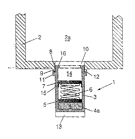
A device with a pyrotechnic gas generator wherein gas pressurizes a hydraulic
circuit via a cartridge-case base, a spring and a pressure piston. The pyrotechnic gas
generator comprises a propellant charge, which is located in a combustion chamber (4)
and is ignited by an electronic igniting unit. The parts of the device are contained in a
housing, which is exchangeably inserted into a wall surrounding the hydraulic circuit.

Revendications

Note : Les revendications sont présentées dans la langue officielle dans laquelle elles ont été soumises.


What is claimed is:
1. A device for pressurizing a hydraulic circuit, comprising:
a pyrotechnic gas generator,
a cartridge-case base disposed in communication with said gas generator;
a spring in contact with said case base and a pressure piston for transmitting
pressure to said hydraulic circuit.
2. A device according to claim 1, wherein said pyrotechnic gas generator
comprises a combustion chamber, a propellant charge disposed in said combustion
chamber and an electronic igniting unit, for igniting said propellant charge.
3. A device according to claim 1, wherein said spring is one of a coil spring, disk
spring and pneumatic spring.
4. A device according to claim 1, further comprising a housing, each of said
pyrotechnic gas generator, said cartridge-case base, said spring and said pressure piston
being disposed in said housing, said hydraulic circuit including a hydraulic circuit wall,
said housing being exchangeably inserted in said wall.
5. A device according to claim 4, wherein said pressure piston acts directly on oil
disposed in said hydraulic circuit, said housing including a shoulder for limiting
movement of said pressure piston.

6. A device according to claim 4, further comprising a lock for limiting movement
of said cartridge-case base, said lock being disposed in said housing.
7. A device according to claim 2, wherein said combustion chamber is surrounded
by a metallic bellows, said metallic bellows for hermetically sealing propellant gases
generated in said combustion chamber.
8. A device according to claim 2, wherein said electronic igniting device is
provided with a heating wire, said igniting device acting only on said heating wire
whereby said heating wire ignites said propellant charge.

Description

Note : Les descriptions sont présentées dans la langue officielle dans laquelle elles ont été soumises.


- 2158398
I)ocket # 45~10
DE~CE FOR A HY~RAUl,IC CI~RCUIT
FIELD OF THE ~ NTION
~e precent inventiQ~ per~ains to a dev~ce which pressur~es a hydraulic CiTCUit.
BACKGROU~ OF THE INVENTION
S Many u~its in recovely and rescue operatio~s, switch-offsystems with high-voltage
cir~uits. Opening u~it~ for emerge~y dools, et~., are operated hydraulically It is
important here to rapidly pressurize the hydraulic circuits used for this purpose in order
to make it possible to carIy out the actuation reliab1y. The pressure nccessa~y for the
hydraulic circuits is supplied by units whic~ do not start rapidly or oten do ~ot St~lt at
all, especially if 1hey ~ave been out of operatio~ for a lo~g time. T~ere~ore, tlle unit in
questio~ ca~not ~c use~, or often it ç~ot be used rapidly enough.
DE 3g 37 032 A1 discloses a pyrotechnic gas generator in wh~ch a hi~h-pressure
housin~ accomn~odating a pressuri~ed gas-generating capsule is s~l~rounded by a medium-

2158398
pressure housing~ The area of ~e discharge openin~s fronl the mediun~-pressure hou~ing
i~ considerably la~ger than tbe area of tbe dischar~e op~nin~ from the hi~h-pressure
housin~ into tlle medium-pressure housing. This gas gellerator is suitable, e.g., for a
pyrotechnic force-generatirlg element, in which the gas discharged from the openings of
the nledlum-pressure housi~g irnp~cts a piston which gener~tes ~ pushiD~ action.
SUMMAR~ A~) Q~JECTS OF THE INVE~TION
The pri~a~y object of the present invention is to design a device of the type
described ~n the introductio~ such that the hydrau]ic circuit is pressurized rapidly and
reliably when needed.
~0 According tc) the invention, a device is provided w~ich pressurizes a hyd~alllic
circuit. A device includes a pyrotechnic gas generator for generating gas for pressurizing
the hydraulic circuit. The pressure is related to the hydraulic circuit by use of a
cartndge-case base, spring a~d a p~ess~lre piston.
l~e pyrotechnîc gas generator preferably camprises ~ propellant c~arge which is
15 located within a combustion chamber a~d which is ignited by an electronic ignitlng unit.
The spring is pre~erably one of a coil spnng~ a disk spring or a pneur~atic sp~ing.
The devi~e for pxe~uri~iP~ is preferably pro~e~ as ~ unit contained in a housing which
is exchangeably inserted into a wall surrounding a hydraulic tank connected to the
hydraulic circui~. Oil is disposed witllin the tank and the pressure piston acts direc-tly on
20 the oil in tbe hydraulic tank. I~he movenlent of the piston is limited by a shoulder
located at an e~d of the unit housing. The movennent of the cartridge-case base i~
limited by a lo. c~ means, prefera~ly a lo~k pres~nt in tl~e h~using.
The combustion chamber is preerably surrounded b~ a ~etallic bellows. ~his
her~etically seals the propelIant gases whic.h are generated in the combustion chamber.

-
_ ~158398
The electronic igmting umt, which is nornlally provided with a pyrotechniG igniter piece,
ac~s only on a heating w~re, which ~ire then will ignite the propellant charge.
~ e essential advantage of the present invention is that the g~s of the gas
generator can ~e re~iably ge~erated by ~le pyrotec.hnic de~ice even after ~ra~ for
5 se~eral years without any rnaintenance of the assembly unit. It is generated i~ a fractioll
of one second, a~d it can thus pressurize the hydraulic circuit ~ia t~e cartridge-case ~ase,
t~e spring and tbe pressule piston. The spr~ng guarantees that the pressure ~cti~g on
tlle pressure piston can be maintaiJ~ed for a short time. In many units, e.g., emergency
do~l~, a sin~le-tim~ pressure, wh;~:h is exerted by the device according to the prese~t
10 in~rention, is sufficient, wheIeas in other u~its, in which the hydraulic circuit n~ust be
under pr~ssure for a long time, tlle de~ice bridges o~er the time elapsing until an
emergency unit starts up and is fully able to be used.
The pyrotechnic gas ~ge~erator of the dev~ce comprises ~ propellant char~e (known
Ln itself), whicb is located in a combustion chamber and is ignited by an electrollic
15 igniting unit with or without an igniter piece Dependin~ on ~e existing possibility, the
elec~ronic igniting unit is supplied with power current or ~om a battely. The ~pring,
which m~i~t~ s the g~ pressure for ~ l~n~er ti~e, may be a coil spr~, a disk spring
or a pneumatic sp~ng. All parts of the device are accommodated in a housing~ whi~
is exchangeably inserted i~to a wall of ~e hydraulic circuit l)epending on the task, a
20 screw plug, a bayonet catch or a sliding closu~e may be used. The exchangeabil;~,r
guarantees rap~d restoration of the abili~ to function after the use of t31e de~i~e.
Experience has sho~n that g~s generators funGtion reliably for rnany years and require
no maintenance.
T~e valious features of novelty whic~ cbaracterize the inve~tion are pointed ou~

2158398
with parti~ul~r~ty in the clain~s annexed to and forn~1ng a part of this disclosure. For a
better llnderstanding of the i~vention, its operatin~ advantages a~d specific objects
~ttained by itf7 uses, referen~e is D~ade to the accompa~yin~ dra~ngs and d~scriptive
matter in which a preferred e~nbodiment of the In~e~tion is illustrat~
~3RIE~ DESCRIPTION OF THE DRAWINGS
In the drawings:
The csnly ~7ure is a sectional v~ew of the dev~c& for hydrauli~ ~ircuit accordin~ to
the invention.
DET~ Fn OESCRIPTIO~ OF THE PREFERRED
EMBODIME~NT
The only i;gure sehema~ically sl~ows a device 1, whi~ can be illserted i~ltO a wall
2 of a hyd~aulic tank. A combustion chamber 4 with a pr~pellallt charge 4a1 a cartridge-
case ~a~7e 57 a c4il ~pr~n~ 6, and a p~ssure piston 7 are ~¢ommodated in a housing 3.
The housing 3 is screwed ~ith a threaded part 8 into a mountin~ hole 10 of the v.tall 2.
T~e hole IO is provided with a thickening 9, and it is sealed via a sb,oulder 11, into which
an O-r~ng 12 is inserted. An electronic ignitillg onit 13 is attached to the housing 3.
The dev~ce functions as follows. After the electronic ;gniting unit 13 has been
switched OD by ~eans of po~er current or a battery available ;D the electronic igniting
unit 13, the propellant cha~ge 4a is ignited. The gas generated presses the eart~idge-c~se
2~ base 5, the pressure is transmitted to the coil spring 6 and to the pressure pisto~ 7, which
exerts the desired p~essure on the hydraulic oil ~a pre$e~t in a spa~e 14 hbove the
pressure pisto~ 7 and in the hyd~aulic tank 2. The ma~mllm stroke of the c~rt~idge-c~se
base S is limited by a lock 15~ and that of thc pressure pistolJ 7 is lin~ited by a shoulder
16. rhe sp~ing 6 maintains the pressure actin~ on the hydraulic oil. When the

215 8398
co~bustion ~hamber 4 wi~h t~e propellant charge 4a is sulrounded by a metallic bellows
in a man~er not shown, the propellant ~ases genera~ed are hermeticaUy sealed, so that
no propellant gas molecules can esçape to the outside.
While a ~p~cific ~mbodime~t of the ill~ention h~s beeP ~hown an~ described in
S deta~l to illustrate the application of the p~inciples of the in~eIltion~ it will be uDders~ood
that the inven~ion may be embodied o~en~ise witho~lt departing ~o~ such principles.

Dessin représentatif
Une figure unique qui représente un dessin illustrant l'invention.
États administratifs

2024-08-01 : Dans le cadre de la transition vers les Brevets de nouvelle génération (BNG), la base de données sur les brevets canadiens (BDBC) contient désormais un Historique d'événement plus détaillé, qui reproduit le Journal des événements de notre nouvelle solution interne.

Veuillez noter que les événements débutant par « Inactive : » se réfèrent à des événements qui ne sont plus utilisés dans notre nouvelle solution interne.

Pour une meilleure compréhension de l'état de la demande ou brevet qui figure sur cette page, la rubrique Mise en garde , et les descriptions de Brevet , Historique d'événement , Taxes périodiques et Historique des paiements devraient être consultées.

Historique d'événement

Description Date
Le délai pour l'annulation est expiré 1999-09-15
Demande non rétablie avant l'échéance 1999-09-15
Réputée abandonnée - omission de répondre à un avis sur les taxes pour le maintien en état 1998-09-15
Demande publiée (accessible au public) 1996-03-18

Historique d'abandonnement

Date d'abandonnement Raison Date de rétablissement
1998-09-15

Taxes périodiques

Le dernier paiement a été reçu le 1997-09-11

Avis : Si le paiement en totalité n'a pas été reçu au plus tard à la date indiquée, une taxe supplémentaire peut être imposée, soit une des taxes suivantes :

  • taxe de rétablissement ;
  • taxe pour paiement en souffrance ; ou
  • taxe additionnelle pour le renversement d'une péremption réputée.

Les taxes sur les brevets sont ajustées au 1er janvier de chaque année. Les montants ci-dessus sont les montants actuels s'ils sont reçus au plus tard le 31 décembre de l'année en cours.
Veuillez vous référer à la page web des taxes sur les brevets de l'OPIC pour voir tous les montants actuels des taxes.

Historique des taxes

Type de taxes Anniversaire Échéance Date payée
TM (demande, 2e anniv.) - générale 02 1997-09-15 1997-09-11
Titulaires au dossier

Les titulaires actuels et antérieures au dossier sont affichés en ordre alphabétique.

Titulaires actuels au dossier
DAIMLER-BENZ AEROSPACE AG
Titulaires antérieures au dossier
PETER LELL
Les propriétaires antérieurs qui ne figurent pas dans la liste des « Propriétaires au dossier » apparaîtront dans d'autres documents au dossier.
Documents

Pour visionner les fichiers sélectionnés, entrer le code reCAPTCHA :


Pour visualiser une image, cliquer sur un lien dans la colonne description du document. Pour télécharger l'image (les images), cliquer l'une ou plusieurs cases à cocher dans la première colonne et ensuite cliquer sur le bouton "Télécharger sélection en format PDF (archive Zip)" ou le bouton "Télécharger sélection (en un fichier PDF fusionné)".

Liste des documents de brevet publiés et non publiés sur la BDBC .

Si vous avez des difficultés à accéder au contenu, veuillez communiquer avec le Centre de services à la clientèle au 1-866-997-1936, ou envoyer un courriel au Centre de service à la clientèle de l'OPIC.


Description du
Document 
Date
(aaaa-mm-jj) 
Nombre de pages   Taille de l'image (Ko) 
Description 1996-03-17 5 172
Abrégé 1996-03-17 1 13
Revendications 1996-03-17 2 45
Dessins 1996-03-17 1 17
Dessin représentatif 1999-06-24 1 15
Courtoisie - Lettre d'abandon (taxe de maintien en état) 1998-10-12 1 184
Courtoisie - Lettre du bureau 1995-11-28 1 36