Sélection de la langue

Search

Sommaire du brevet 2158406 

Énoncé de désistement de responsabilité concernant l'information provenant de tiers

Une partie des informations de ce site Web a été fournie par des sources externes. Le gouvernement du Canada n'assume aucune responsabilité concernant la précision, l'actualité ou la fiabilité des informations fournies par les sources externes. Les utilisateurs qui désirent employer cette information devraient consulter directement la source des informations. Le contenu fourni par les sources externes n'est pas assujetti aux exigences sur les langues officielles, la protection des renseignements personnels et l'accessibilité.

Disponibilité de l'Abrégé et des Revendications

L'apparition de différences dans le texte et l'image des Revendications et de l'Abrégé dépend du moment auquel le document est publié. Les textes des Revendications et de l'Abrégé sont affichés :

  • lorsque la demande peut être examinée par le public;
  • lorsque le brevet est émis (délivrance).
(12) Brevet: (11) CA 2158406
(54) Titre français: SYSTEME DE MANOEUVRE POUR FENETRE
(54) Titre anglais: WINDOW OPERATOR ASSEMBLY
Statut: Périmé et au-delà du délai pour l’annulation
Données bibliographiques
(51) Classification internationale des brevets (CIB):
  • E05F 11/00 (2006.01)
  • E05F 11/16 (2006.01)
(72) Inventeurs :
  • KLIMEK, DAVID J. (Etats-Unis d'Amérique)
  • WRIGHT, THOMAS (Etats-Unis d'Amérique)
(73) Titulaires :
  • SNE ENTERPRISES, INC.
(71) Demandeurs :
  • SNE ENTERPRISES, INC. (Etats-Unis d'Amérique)
(74) Agent: FINLAYSON & SINGLEHURST
(74) Co-agent:
(45) Délivré: 1998-11-03
(22) Date de dépôt: 1995-09-15
(41) Mise à la disponibilité du public: 1996-03-17
Requête d'examen: 1995-09-15
Licence disponible: S.O.
Cédé au domaine public: S.O.
(25) Langue des documents déposés: Anglais

Traité de coopération en matière de brevets (PCT): Non

(30) Données de priorité de la demande:
Numéro de la demande Pays / territoire Date
307,243 (Etats-Unis d'Amérique) 1994-09-16

Abrégés

Abrégé français

L'invention concerne un dispositif de manoeuvre pour une fenêtre à battants comprenant un cadre et un châssis supportant la vitre. Le dispositif de manoeuvre est monté sur le cadre et un bras allongé relie le dispositif de manoeuvre et le châssis. Le mouvement du bras entraîne le déplacement du châssis par rapport au cadre pour l'ouverture et la fermeture de la fenêtre. Le bras du dispositif de manoeuvre comprend une poignée pivotante et se déplaçant linéairement entre une première et une deuxième positions. Un système d'engrenage à rochet permet de raccorder la poignée et le bras et d'entraîner le mouvement du bras en réponse au mouvement de la poignée. Un sélecteur associé à la poignée et au système d'engrenages sert à commander le sens de déplacement du châssis en réponse aux mouvements de la poignée. Un système de verrouillage est prévu pour bloquer le système d'engrenages et empêcher celui-ci de bouger sous l'effet des charges imposées sur le châssis et transmises au système d'engrenages par le châssis et le bras du dispositif de manoeuvre. Le système de verrouillage est repoussé en position engagée, mais peut être dégagé par le mouvement de la poignée de manoeuvre et d'un dispositif qui y est associé.


Abrégé anglais


An operator assembly for a casement window that
includes a frame and a pane carrying sash. The operator
assembly is mounted to the frame and an elongated arm
connects the operator assembly and the sash. Movement of
the arm moves the sash relative to the frame for opening
and closing the window. The operator arm includes a
pivotally mounted and linerally moveable handle which is
moveable between a first and second position. A ratchet-
type gearing system is provided to connect the handle and
operator arm and to effect movement of the operator arm in
response to movement of the handle. A selector associated
with the handle and gearing system is provided to effect and
control the direction of sash movement in response to the
movements by the handle. A locking system is provided to
engage the gearing system to prevent movement of the gearing
system due to loads on the sash that are transmitted to the
gearing system through the sash and operator arm. The locking
system is biased to an engaged position but is disengaged by
movement of the actuator handle and a device associated
therewith.

Revendications

Note : Les revendications sont présentées dans la langue officielle dans laquelle elles ont été soumises.


The embodiments of the invention in which an exclusive property
or privilege is claimed are defined as follows:
1. An operator assembly having an operator arm for
opening and closing a window having a frame and a sash pivotally
secured to the frame for pivoting about an axis associated with
the frame and the sash, said operator assembly comprising:
an operator body constructed for securement to a frame
and defining a first and a second position;
an elongated operator arm having one end constructed
to engage a sash, the other end gearingly secured to the
operator body and constructed to move in a plane substantially
transverse to a frame pivot axis;
a force multiplying gearing system positioned within
said body and operatively associated with said other end of the
operator arm;
an elongated graspable handle, pivotally mounted
within said body for movement between the first and the second
position and in a plane substantially parallel to the plane of
movement of the operator arm, said handle having one end
positioned within the body and operatively associated with the
force multiplying gearing system and the other end extending
away from the sash;
so that movement of the handle between the first and
the second position, causes movement of the force multiplying
gearing system and pivotable movement of the operator arm to
cause movement of the sash; and
wherein the force multiplying gearing system includes
a first pinion gear constructed to be rotated by movement of the
13

handle, a first large spur gear rotatably meshed with first
pinion gear for rotation, a second small gear journaled to the
first large spur gear for rotation therewith, a second large
spur gear which forms part of the operator arm and rotatably
enmeshed with the second small gear, whereby movement of the
handle causes the first pinion gear to rotate, which drives the
first large spur gear, the rotation of which rotates the second
small gear, which drives the operator arm spur gear.
2. An operator assembly having an operator arm for
opening and closing a window having a frame and a sash pivotally
secured to the frame for pivoting about an axis associated with
the frame and the sash, said operator assembly comprising:
an operator body constructed for securement to a frame
and defining a first and a second position;
an elongated operator arm having one end constructed
to engage a sash, the other end gearingly secured to the
operator body and constructed to move in a plane substantially
transverse to a frame pivot axis;
a force multiplying gearing system positioned within
said body and operatively associated with said other end of the
operator arm;
an elongated graspable handle, pivotally mounted
within said body for movement between the first and the second
position and in a plane substantially parallel to the plane of
movement of the operator arm, said handle having one end
positioned within the body and operatively associated with the
force multiplying gearing system and the other end extending
away from the sash;
14

so that movement of the handle between the first and
the second position, causes movement of the force multiplying
gearing system and pivotable movement of the operator arm to
cause movement of the sash;
wherein the gearing system is operable to move the
operator arm between a sash open and a sash closed position and
the handle includes an assembly for selective operation of the
operator arm to the open or close position; and
wherein there is provided a gear-type ratchet wheel
mechanism associated with the force multiplying gear system and
a pawl mechanism associated with the handle and selector
assembly so that said handle can be moved in one direction to
engage the gearing system but when moved in the opposite
direction the pawl and gear are gearingly disengaged.
3. An operator assembly as in claim 2 wherein there is
provided a locking mechanism to prevent undesired movement of
the sash, wherein there is provided a first locking mechanism
part associated with the force multiplying gearing system and a
second locking mechanism part associated with the operator body
and bias for engagement with the first part to prevent movement
of the force multiplying system relative to the operator body.
4. An operator assembly as in claim 3 wherein said first
part comprises a first gear member associated with the force
multiplying gearing system and said second part includes a
second gear member constructed and arranged to engage the first
gear member.
5. An operator assembly as in claim 3 wherein a biasing

member is provided in association with the operator body and
said second part so as to urge said second part into engagement
with said first part.
6. An operator assembly as in claim 5 wherein there is
provided a release mechanism associated with the second locking
mechanism part and the handle to release the second locking
member from engagement with the first locking member only upon
movement of the handle.
7. An operator assembly having an operator arm for
opening and closing a window having a frame and a sash pivotally
secured to the frame for pivoting about an axis associated with
the frame and the sash, said operating assembly comprising:
an operator body constructed for securement to a frame
and defining a first and a second position;
an elongated operator arm having one end constructed
to engage a sash, the other end gearingly secured in said
operator body and constructed to move in a plane substantially
transverse to a frame pivot axis;
a force multiplying gearing system positioned within
said body and operatively associated with said other end of the
operator arm;
an elongated graspable handle, pivotally mounted in
said body for movement between the first and the second position
in a plane substantially parallel to the plane of movement of
the operator arm, said handle having one end positioned within
the body and operatively associated with the force multiplying
gearing system and the other end extending away from the sash;
16

so the movement of the handle between the first and
second position causes movement of the force multiplying gear
system and pivotable movement of the operator arm to cause
movement of the sash;
wherein there is provided a locking mechanism to
prevent undesired movement of the sash and there is provided a
first locking mechanism part associated with the force
multiplying gearing system and a second locking mechanism part
associated with the operator body and biased with the first part
to prevent movement of the force multiplying system relative to
the operator body; and
wherein the first locking mechanism part comprises a
first gear member associated with the force multiplying gearing
system and the second locking mechanism part is an apertured
plate having gear teeth surrounding the aperture which is biased
into engagement with the first gear and a ribbed release plate
associated with the handle and engagable with the apertured
plate so as to release the teeth from engagement upon movement
of the handle.
8. An operator assembly having an operator arm for
opening and closing a window having a frame and a sash pivotally
secured to the frame for pivoting about an axis associated with
the frame and the sash, said operating assembly comprising:
an operating body constructed for securement to a
frame and defining a first and a second position;
an elongated operator arm having one end constructed
to engage a sash, the other end gearingly secured in said
operator body and constructed to move in a plane substantially
17

transverse to a frame pivot axis;
a force multiplying gearing system positioned within
said body and operatively associated with said other end of the
operator arm;
an elongated graspable handle, pivotally mounted in
said body for movement between the first and the second position
in a plane substantially parallel to the plane of movement of
the operator arm, said handle having one end positioned within
the body and operatively associated with the force multiplying
gearing system and the other end extending away from the sash;
so the movement of the sash between the first and
second position causes movement of the force multiplying gear
system and pivotable movement of the operator arm to cause
movement of the sash; and
wherein there is provided a pawl mechanism mounted to
the handle and engagable with the force multiplying gearing
system and a selector mechanism associated with the handle so as
to selectively urge the pawl into engagement with the gearing
system and drive the gearing system in one direction when the
handle is moved in a first direction and to release the gearing
system when the handle is moved in the reverse direction.
9. An operator assembly as in claim 8 wherein the pawl
engages the gearing system to cooperate in driving the operator
arm to a sash open position or to a sash closed position.
10. An operator assembly as in claim 9 wherein the
selector mechanism includes a selector switch which includes a
tipped mechanism engaging the pawl which mechanism is moveable
18

to cause a first tooth of the pawl to engage the gearing system
or to cause a second tooth of the pawl to engage the pawl for
driving in a reverse direction.
11. An operator assembly having an operator arm for
opening and closing a window having a frame and a sash pivotally
secured to the frame for pivoting about an axis associated with
the frame and the sash, said operator assembly comprising:
an operator body constructed for securement to a frame
and defining a first and a second position;
an elongated operator arm having one end constructed
to engage a sash and the other end gearingly secured in said
operator body;
a force multiplying gearing system positioned within
said body and operatively associated with said other end of the
operator arm;
an elongated and graspable handle, pivotally mounted
within said body for a linear movement between the first and the
second position, said handle having one end positioned within
the body and operatively associated with the force multiplying
gearing system and the other end extending away from the sash;
so that movement of the handle between the first and
the second position, causes movement of the force multiplying
gear system and pivotal movement of the operator arm to cause
movement of a sash;
wherein the gearing system is operable to move the
operator arm between a sash open and a sash closed position and
the handle includes an assembly for selective operation of the
operator arm to the open or closed position; and
19

wherein there is provided a gear-type ratchet wheel
mechanism associated with the force multiplying gear system and
a pawl mechanism associated with the handle and selector
assembly so that said handle can be moved in one direction to
engage the gearing system but when moved in the opposite
direction the pawl and gear system are gearingly disengaged.
12. An operator assembly having an operator arm for
opening and closing a window having a frame and a sash pivotally
secured to the frame for pivoting about an axis associated with
the frame and the sash, said operator assembly comprising:
an operator body constructed for securement to a frame
and defining a first and a second position;
an elongated operator arm having one end constructed
to engage a sash and the other end gearingly secured in said
operator body;
a force multiplying gearing system positioned within
said body and operatively associated with said other end of
the operator arm;
an elongated and graspable handle, pivotally mounted
within said body for a linear movement between the first and the
second position, said handle having one end positioned within
the body and operatively associated with the force multiplying
gearing system and the other end extending away from the sash;
so that movement of the handle between the first and
the second position, causes movement of the force multiplying
gear system and pivotal movement of the operator arm to cause
movement of a sash; and
wherein the force multiplying gearing system includes

a first pinion gear constructed to be rotated by movement of the
handle, a first large spur gear rotatably meshed with said first
pinion gear for rotation, a second small gear journalled to the
first large spur gear for rotation therewith and a second large
spur gear which forms part of the operator arm and rotatably
enmeshed with said second small gear, whereby movement of the
handle causes the first pinion gear to rotate, which drives the
first large spur gear, the rotation of which rotates the second
small gear, which drives the operator arm spur gear.
13. An operator assembly having an operator arm for
opening and closing a window having a frame and a sash pivotally
secured to the frame for pivoting about an axis associated with
the frame and the sash, said operator assembly comprising:
an operator body constructed for securement to a frame
and defining a first and a second position;
an elongated operator arm having one end constructed
to engage a sash and the other end gearingly secured in said
operator body;
a force multiplying gearing system positioned within
said body and operatively associated with said other end of the
operator arm;
an elongated and graspable handle, pivotally mounted
within said body for a linear movement between the first and the
second position, said handle having one end positioned within
the body and operatively associated with the force multiplying
gearing system and the other end extending away from the sash;
so that movement of the handle between the first and
the second position, causes movement of the force multiplying
21
.. ~
, ,.

gear system and pivotal movement of the operator arm to cause
movement of a sash;
wherein there is provided a locking mechanism to
prevent undesired movement of a sash, wherein there is provided
a first locking mechanism part associated with the force
multiplying gearing system and a second locking mechanism part
associated with the operator body and biased for engagement with
the first part to prevent movement of the force multiplying
system relative to the operator body; and
wherein the first locking mechanism part comprises a
first gear member associated with the force multiplying gearing
system and the second locking mechanism part is an apertured
plate having gear teeth surrounding the aperture which is biased
into engagement with the first gear and a ribbed release plate
associated with the handle and engagable with the apertured
plate so as to release the teeth from engagement upon movement
of the handle.
14. An operator assembly having an operator arm for
opening and closing a window having a frame and a sash pivotally
secured to the frame for pivoting about an axis associated with
the frame and the sash, said operator assembly comprising:
an operator body constructed for securement to a frame
and defining a first and a second position;
an elongated operator arm having one end constructed
to engage a sash and the other end gearingly secured in said
operator body;
a force multiplying gearing system positioned within
said body and operatively associated with said other end of the
22

operator arm;
an elongated and graspable handle, pivotally mounted
within said body for a linear movement between the first and the
second position, said handle having one end positioned within
the body and operatively associated with the force multiplying
gearing system and the other end extending away from the sash;
so that movement of the handle between the first and
the second position, causes movement of the force multiplying
gear system and pivotal movement of the operator arm to cause
movement of a sash; and
wherein there is provided a pawl mechanism mounted to
the handle and engagable with the force multiplying gearing
system and a selector mechanism associated with the handle so as
to selectively urge the pawl into engagement with the gearing
system and drive the gearing system in one direction when the
handle is moved in a first direction and to release the gearing
system when the handle is moved in the reverse direction.
15. An operator assembly as in claim 14 wherein a pawl
engages the gearing system to cooperate in driving the operator
arm to a sash open position or to a sash closed position.
16. An operator assembly as in claim 15 wherein the
selector mechanism includes a selector switch which includes a
tipped mechanism engaging the pawl which mechanism is moveable
to cause a first tooth of the pawl to engage the gearing system,
or to cause a second tooth of the pawl to engage the pawl for
driving in a reverse direction.
17. An operator assembly having an operator arm for
23

opening and closing a window having a frame and a sash pivotally
secured to the frame for pivoting about an axis associated with
the frame and the sash, said operator assembly comprising:
an operator body constructed for securement to a frame
and defining a first and a second position;
an elongated operator arm having one end constructed
to engage a sash and the other end gearingly secured in said
operator body and constructed to move in a plane substantially
transverse to a sash/frame pivot axis;
a force multiplying gearing system positioned within
said body and operatively associated with said other end of the
operator arm;
an elongated and graspable handle, pivotally mounted
within said body for movement between the first and the second
position and in a plane substantially parallel to the plane of
movement of the operator arm, said handle having one end
positioned within the body and operatively associated with the
force multiplying gearing system and the other end extending
away from the sash;
so that movement of the handle between the first and
the second position, causes movement of the force multiplying
gear system and pivotal movement of the operator arm to cause
movement of a sash;
wherein the gearing system is operable to move the
operator arm between a sash open and a sash closed position and
the handle includes an assembly for selective operation of the
operator arm to the open or closed position;
wherein there is provided a gear-type ratchet wheel
24

mechanism associated with the force multiplying gear system and
a pawl mechanism associated with the handle and selector
assembly so that said handle can be moved in one direction to
engage the gearing system but when moved in the opposite
direction the pawl and gear are gearingly disengaged;
wherein the force multiplying gearing system includes
a first pinion gear constructed to be rotated by movement of the
handle, a first large spur gear rotatably meshed with said first
pinion gear for rotation, a second small gear journalled to the
first large spur gear for rotation therewith and a second large
spur gear which forms part of the operator arm and rotatably
enmeshed with said second small gear, whereby movement of the
handle causes the first pinion gear to rotate, which drives the
first large spur gear, the rotation of which rotates the second
small gear, which drives the operator arm spur gear;
wherein there is provided a locking mechanism to
prevent undesired movement of a sash, wherein there is provided
a first locking mechanism part associated with the force
multiplying gearing system and a second locking mechanism part
associated with the operator body and biased for engagement with
the first part to prevent movement of the force multiplying
system relative to the operator body;
wherein a biasing member is provided in association
with operator body and said second part so as to urge said
second part into engagement with said first part;
wherein said first part comprises a first gear member
associated with the force multiplying gearing system and said
second part includes a second gear member constructed and

arranged to engage the first gear member;
wherein there is provided a release mechanism
associated with the second locking mechanism part and the handle
to release the second locking member from engagement with the
first locking member only upon movement of the handle;
wherein the first locking mechanism part comprises a
first gear member associated with the force multiplying gearing
system and the second locking mechanism part is an apertured
plate having gear teeth surrounding the aperture which is biased
into engagement with the first gear and a ribbed release plate
associated with the handle and engagable with the apertured
plate so as to release the teeth from engagement upon movement
of the handle;
wherein the handle is moveable substantially parallel
to the frame in which the operator body is secured;
wherein there is provided a pawl mechanism mounted to
the handle and engagable with the force multiplying gearing
system and a selector mechanism associated with the handle so as
to selectively urge the pawl into engagement with the gearing
system and drive the gearing system in one direction when the
handle is moved in a first direction and to release the gearing
system when the handle is moved in the reverse direction;
wherein the pawl engages the gearing system to
cooperate in driving the operator arm to a sash open position or
to a sash closed position; and
wherein the direction selector mechanism includes a
selector switch which includes a tipped mechanism engaging the
pawl which mechanism is moveable to cause a first tooth of the
26

pawl to engage the gearing system, or to cause a second tooth of
the pawl to engage the pawl for driving in a reverse direction.
27

Description

Note : Les descriptions sont présentées dans la langue officielle dans laquelle elles ont été soumises.


21~840~
-- WINDOW OPERATOR ASSEMBLY
BACKGROUND OF THE INVENTION
This invention relates to swinging windows of
the casement or awning style and more particularly, to an
operator assembly of the type used to open and/or close
the window.
Casement and awning style windows have been and
are popular. Such a window is shown in U.S. Patent
4,837,977, Mauro. In a casement window, there is a frame
which is fixed in an opening in a building. The window
includes a sash, which carries a pane that is mounted to
the frame about an axis usually along one side of the sash
and the frame. To open or close the window, the sash is
pivoted about the axis. The sash is swung open and closed
about the pivot axis by an operator arm which is secured at
one end to the sash and at the other end to an operator
assembly associated with the frame. The operator assembly
includes a handle for moving the operator arm in response to a
user's actions. The operator assembly is secured to the frame
on the inside of the window so as to permit the sash to swing
on the outside between a closed position against the frame and
open position away from the frame.
Many operator assemblies are crank style devices,
where a handle rotatable about an axis oblique to the frame
and operates a gear train that moves the arm to open or close
the sash.

21 584Q6
A disadvantage to crank style operator assemblies is
the rotary motion of the handle and the distance the operator
handle extends from the frame into the room. This may be
manifested by handle interference with draperies or blinds.
Thus, this invention seeks to provide a system for
opening and closing a casement or awning style window, which is
not of the crank style and whose inward extent is minimized.
In the crank style system, the handle may obstruct the
removal and installation of a screen accessory or hinder
cleaning of the pane.
Thus, this invention also seeks to provide an operator
assembly with a handle that is not obstructive.
In some situations a linear style or linearly movable
operator assembly has been used. But these assemblies require
large amounts of force to operate or may open the sash only to a
limited extent, rather than the full extent (i.e. 45 degrees
rather than 90 degrees).
Thus, the invention further seeks to provide an
operator assembly that has a linearly movable handle which has a
high degree of mechanical advantage and permits a full range of
sash motion.
It is also been found that in some positions the
handle may be difficult to use, especially for older people,
particularly if they suffer from arthritis or similar diseases.
Further still the invention seeks to provide an
operator with a handle that is easy to use and which exhibits a
high degree of mechanical advantage.
Sometimes the crank style handle may be difficult to
.~

21 58406
rotate depending upon its position and thus be uneven to use and
may cause the user's knuckles to strike the sill.
Still further, this invention seeks to provide an
operator with a handle that is easy and convenient to use and is
not position sensitive.
These and other aspects of this invention will become
apparent from the following disclosure and appended claims.
SUMMARY OF THE INVENTION
There is provided by this invention a ratchet-style
operator assembly which includes a handle that, although
pivotally mounted, has a linear-style to its motion.
The operator assembly is mounted to the frame, is not
obtrusive, is easy and convenient to use, exhibits a high degree
of mechanical advantage so as to be capable of smooth operation.
The invention pertains to an operator assembly having
an operator arm for opening and closing a window having a frame
and a sash pivotally secured to the frame for pivoting about an
axis associated with the frame and the sash. The operator
assembly includes an operator body constructed for securement to
a frame and defining a first and a second position and an
elongated operator arm having one end constructe'd to engage a
sash and the other end gearingly secured in the operator body.
A force multiplying gearing system is positioned within the body
and is operatively associated with the other end of the operator
arm. An elongated graspable handle is pivotally mounted within
the body for linear movement between the first and the second
position, the handle having one end positioned within the body
and operatively associated with the force multiplying gearing

2 1 58406
system and the other end extending away from the sash, so that
movement of the handle between the first and the second
position, causes movement of the force multiplying gearing
system and pivotable movement of the operator arm to cause
movement of the sash.
In one aspect of the invention, the force multiplying
gearing system includes a first pinion gear constructed to be
rotated by movement of the handle, a first large spur gear
rotatably meshed with first pinion gear for rotation, a second
small gear journalled to the first large spur gear for rotation
therewith, a second large spur gear which forms part of the
operator arm and rotatably enmeshed with the second small gear,
whereby movement of the handle causes the first pinion gear to
rotate, which drives the first large spur gear, the rotation of
which rotates the second small gear, which drives the operator
arm spur gear. In another aspect to the invention, the gearing
system is operable to move the operator arm between a sash open
and a sash closed position and the handle includes an assembly
for selective operation of the operator arm to the open or close
position. A gear-type ratchet wheel mechanism is associated
with the force multiplying gear system and a pawl mechanism is
associated with the handle and selector assembly so that the
handle can be moved in one direction to engage the gearing
system but when moved in the opposite direction the pawl and
gear are gearingly disengaged.
Still further the invention provides an operator
assembly including a locking mechanism to prevent undesired
movement of the sash whereas there is provided a first locking

21 58406
mechanism part associated with the force multiplying gearing
system and a second locking mechanism part associated with the
operator body and biased with the first part to prevent movement
of the force multiplying system relative to the operator body.
The first locking mechanism part comprises a first gear member
associated with the force multiplying gearing system and the
second locking mechanism part is an apertured plate having gear
teeth surrounding the aperture which is biased into engagement
with the first gear. A ribbed release plate is associated with
the handle and is engagable with the apertured plate so as to
release the teeth from engagement upon movement of the handle.
Further still, there is provided an operator assembly
wherein a pawl mechanism is mounted to the handle and is
engagable with the force multiplying gearing system with a
selector mechanism associated with the handle so as to
selectively urge the pawl into engagement with the gearing
system and drive the gearing system in one direction when the
handle is moved in a first direction and to release the gearing
system when the handle is moved in the reverse direction.
More particularly, the operator assembly includes a
handle whose movement is parallel to the frame and of- a linear
style. The handle includes a pawl mechanism that engages a
ratchet wheel/gear that controls the direction of operation and
connects the actuator handle to the gear system that in turn is
connected to the operator arm and sash. The handle includes a
selector that is movable between a first and a second position
or vice-versa, which permits operation of the operator arm so as
to open or close the sash. The linear handle movement is more
convenient than the rotary movement. The handle is connected to
A~
, ~ .
, ~, .

2 1 58406
the operator arm through a force multiplying gearing system that
in effect increases the opening power.
More specifically, the handle activates a pawl that
drives a ratchet wheel/gear in a clockwise or counter clockwise
direction. This drives a gear system that includes a first
pinion in common with ratchet wheel, that engages and rotates a
first large spur gear that is commonly mounted with a second
pinion and that rotates a large spur gear which is part of the
operator arm. Several strokes of the handle will open or close
the sash. Operation of the selector and handle in the opposite
direction causes the sash to move in the opposite direction.
This gearing system provides a suitable mechanical advantage.
4s

215840~
,
A lock plate is provided which is mounted to
the operator housing and biased to engage the gear/ratchet
wheel so as to prevent undesired movement of the operator such
as caused by wind forces against the sash. A plate and cam or
release mechanism is provided in association with the lock
plate to permit operation of the handle and in effect disable
the locking mechanism.
BRIEF DESCRIPTION OF THE DRAWINGS
FIGURE 1 is a perspective view of a casement-
style window with an operator of this invention mounted to thebottom edge of the frame;
FIGURE 2 is a view of a lower corner of the window
showing the operator and the arm;
FIGURE 3 is a plan-style view of the operator
assembly and showing a slide system associated with the
sash;
FIGURE 4 is a plan view of the operator
assembly with the top plate removed;
FIGURE 5 is a sectional view of the operator
assembly taken along line 5-5 of Figure 4 but with the
top plate in place;
FIGURE 6 is a sectional view taken along line 6-6 of
Figure 4;
FIGURE 7 is an enlarged sectional view of the
top cover, locking plate, and pawl mechanism pivot and

4 0 ~
taken substantially along line 7-7 of Figure 6 with the
locking mechanism operative;
FIGURE 8 is a view like Figure 7 showing a change in
the position with the locking mechanism being disabled;
FIGURE 9 is a perspective view showing the lock
plate mechanism;
FIGURE 10 is a view similar to Figure 4 with
the top cover and a bug cover removed and showing the
internal operation of the operator including the ratchet
wheel/gear, the pawl mechanism and the handle selection
mechanism; and
FIGURE 11 is a plan view of disassembled
parts of the operator.
DESCRIPTION OF THE PREFERRED EMBODIMENT
Background
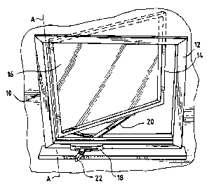
Referring to Figure 1, there is shown a window 10
which includes (1) a frame 12 that is to be mounted in a
building opening; (2) a sash 14 that is pivotally mounted to
the frame along axis A-A; and (3) a transparent pane 16
mounted within the sash. An operator assembly 18 is mounted
to the frame and an operator arm 20 is connected to the
operator assembly 18 and sash 14 for opening and closing the
sash. The operator actuator or handle 22 is pivotally
connected inside the assembly 18 but slides or is linearly
moved from one end of the operator assembly to the other end

~15840~
to operate a gearing system that rotates the arm so as to open
or close the sash. It is noted that the handle moves
essentially parallel to the frame.
The Operator Assembly-Generally
Referring now to Figures 2 and 3, a corner of the
window is shown. The operator arm 20 is pivotally connected
to the operator assembly 18 at one end, and the other end
includes a small roller 24 that rides in a track (not shown)
at the bottom of the sash so as to cause the sash to pivot
about axis A-A as the arm is moved or rotated. A second arm
26 is pivotally secured, adjacent the axis end of the sash, to
the bottom of the sash and the other end of the second arm
slides in track 28 that is mounted to the frame. The arms 20
and 26 and track 28 guide the movement of the sash.
The operator assembly 18 fits within and is
mounted to the frame. The operator assembly includes a
face plate 30, a cover plate 31, and a body portion 32.
The face is exposed when the assembly is completed and
includes an elongated slot 34 through which the actuator
handle fits, rotates and is moveable parallel to the frame or
window sill. The handle 22 includes a selector switch 36 that
cooperates with the a gearing system in the body and is
moveable between a window open (O) and a window closed (C)
position. The operator includes a ratchet style force
multiplying gear system that is housed in general within the
body 32 and connects the actuator handle 22 and operator arm.

2158406
The Operator Gearing System and Ratchet System
The operator handle 22 is pivotally mounted about a
ratchet wheel/gear combination 37. The ratchet wheel/gear
combination forms a first pinion. The first pinion drives a
suitable large diameter drive or spur gear 38 which rotates in
common with a second pinion gear 40. The second pinion gear
40 drives a suitable second large drive or spur gear 42 which
is integral with the operator arm 20. The ratchet wheel/first
pinion gear and the second drive gear are mounted on a common
shaft 44, but it is seen that there is a sliding connection
between the ratchet wheel/gear 37 and gear 42. In other
words, the ratchet wheel/gear 37 and second spur gear 42 do
not rotate together or in unison. But, the first spur gear 38
and second pinion 40 are mounted on the shaft 46 and do rotate
in common.
The actuator handle 22 includes the selector
switch 36. The selector switch is pivotally mounted to
the handle and includes collar 47 that is connected to
the rod 48 that extends along the actuator handle toward
the gearing system. A compression spring 50 is wound about
the rod 48. The spring engages a moveable end tip 52 that
engages a pawl plate 54 which is pivotally mounted to the
handle 22 by headed pin 56 which forms a pivot point.
The pawl 54 includes a pair of selector shoulders 58
and 60 which are selectively engagable by the tip.
It is seen that movement of the selector 36 from

- 21~8406
open (O) to closed (C)(or visa versa) causes the collar 47,
rod 48 and tip to swing from shoulder 58 to shoulder 60. In
so doing, the collar 47 to tip 52 distance may shorten and
then lengthen. These changes are adjusted by space in the tip
and engagement is assured by spring 50.
The pawl includes a pair of gear engagement teeth 62
and 64 which are engagable with the teeth of the ratchet
wheel/gear 37. Thus, by moving or stroking the handle from
one end to the other, the rachet engagement teeth can engage
the ratchet wheel/gear and thus move or rotate the gearing
system. In general the pawl will push the gear teeth on one
stroke. On the reverse stroke the pawl will skip over the
gear teeth. Thus, in the view of Figure 10, the ratchet
wheel/gear 37 will be rotated in the counter clockwise
direction when the handle is moved to the right. But when the
handle is moved to the left, the pawl will skip over the teeth
and the rod 48, tip 52 and spring 50 will adjust as is seen.
The engagement tooth 62 will grab a ratchet wheel/gear tooth
in one direction and will skip or ratchet in the opposite
direction. The skipping movement of the pawl is accommodated
or taken up by the spring 50. Movement of the actuator handle
causes the pawl to move, which engages and causes the ratchet
wheel/gear 37 to move. That causes the first large drive gear
38 and the second pinion gear 40 rotate, thereafter the pinion
gear 40 rotates the second large drive gear 42 and the
operator arm 20.

~158406
Operator Locking System
In order to prevent the sash from moving,
respecially closing, due to wind forces, by applying a force
on the arm 20, a gearing type lock system is incorporated
herein. See Figures 7, 8 and 9. The locking system includes
a locking plate 66 that is hingedly connected to the cover 31
and surrounds the shaft 44. The plate hinges downwardly and
is biased downwardly by leaf spring 67. As seen in Figure 9
the plate includes a plurality of teeth 68 which surround an
aperture 69 that allows the plate to fit into a set of gear-
like teeth 39 projecting upwardly from the ratchet wheel/gear37. The teeth 68 engage the teeth 39 as best seen from Figure
9 so as to lock the ratchet wheel/gear 37, prevent movement
thereof and thus the entire gear train. The biasing spring 67
urges the plate 66 downwardly and into locking engagement.
With reference to Figure 6, it is seen that the plate slopes
or hangs downwardly and is biased downwardly by the leaf
spring 67. Thus, any force applied to the operator arm 20 is
transmitted through the gearing system to the gear 37, but the
gearing system terminates in the engagement of teeth 39 and 68
which prevents rotation of the gearing system.
In order to permit rotation of the gearing system,
or release the system for rotation, it is necessary to lift
the plate 66 and teeth 68 out of engagement with the teeth 39.
This is achieved by the pivot pin cover plate 70. It is seen
that the cover plate 70 is coined or formed upwardly at its

~1~8~06
center 70a so as to, in a sense, cover the pivot pin head 56.
At the top of the cover plate center 70a there is also
provided a short cam like ridge or rib 70b. Reference
is made to Figure 7 where it is seen that the pin 56 rests on
the pawl plate 54 and under the center section 7Oa of the
plate 70 and the ridge 70b rides against the locking plate 66.
In order to raise the plate 66 so as to disengage the teeth 39
and 68, the handle actuator 22 is moved which causes the pin
56, as shown in Figure 8 to slide under the plate 70 thereby
raising the plate 70 and the ridge 70b in turn raises the
locking plate 66.
Thus, it is seen that the gearing mechanism can
operate only under the influence of the handle actuator 22,
but cannot be forced to move due to the wind loads on the sash
and when the handle is not moved.
The Assembly
Referring now to Figure 11, the operator assembly
is shown disassembled. An important feature of the system is
a bug shield or deflector 80 which is arranged in the operator
to prevent insects on the exterior from entering the house
through the operator and through the exposed slot 34. It is
seen from Figure 4 that the actuator, pawl, first pinion
gear and locking plate are positioned above bug shield. On
the other hand, the lower part of the first pinion, the first
large drive gear 38, the second pinion gear 40 and the second
large drive gear 42 are positioned below the bug shield.

~15~D;6
With reference to Figure 11, one can see the
actuator handle 22, the selector 36, the ratchet wheel
and pinion combination 37, the locking gear 39. The first
large spur gear 38 is shown and it is noted that it has a
square bore 38a to match with the shaft 46. On the shaft 46,
the second pinion gear 40 engages the second large spur gear
42 that is part of the operator arm. The locking plate 66 is
seen as well as part of the front face 30. The cover for the
entire body section 32 is also shown.
lo It will be appreciated that modifications and
changes can be made to the foregoing embodiment without
departing from the spirit and scope of this invention.

Dessin représentatif
Une figure unique qui représente un dessin illustrant l'invention.
États administratifs

2024-08-01 : Dans le cadre de la transition vers les Brevets de nouvelle génération (BNG), la base de données sur les brevets canadiens (BDBC) contient désormais un Historique d'événement plus détaillé, qui reproduit le Journal des événements de notre nouvelle solution interne.

Veuillez noter que les événements débutant par « Inactive : » se réfèrent à des événements qui ne sont plus utilisés dans notre nouvelle solution interne.

Pour une meilleure compréhension de l'état de la demande ou brevet qui figure sur cette page, la rubrique Mise en garde , et les descriptions de Brevet , Historique d'événement , Taxes périodiques et Historique des paiements devraient être consultées.

Historique d'événement

Description Date
Inactive : CIB de MCD 2006-03-11
Le délai pour l'annulation est expiré 2004-09-15
Lettre envoyée 2003-09-15
Accordé par délivrance 1998-11-03
Inactive : Taxe finale reçue 1998-06-15
Préoctroi 1998-06-15
Un avis d'acceptation est envoyé 1997-12-22
Lettre envoyée 1997-12-22
Inactive : Renseign. sur l'état - Complets dès date d'ent. journ. 1997-12-16
Inactive : Dem. traitée sur TS dès date d'ent. journal 1997-12-16
Inactive : Approuvée aux fins d'acceptation (AFA) 1997-10-29
Demande publiée (accessible au public) 1996-03-17
Toutes les exigences pour l'examen - jugée conforme 1995-09-15
Exigences pour une requête d'examen - jugée conforme 1995-09-15

Historique d'abandonnement

Il n'y a pas d'historique d'abandonnement

Taxes périodiques

Le dernier paiement a été reçu le 1998-08-12

Avis : Si le paiement en totalité n'a pas été reçu au plus tard à la date indiquée, une taxe supplémentaire peut être imposée, soit une des taxes suivantes :

  • taxe de rétablissement ;
  • taxe pour paiement en souffrance ; ou
  • taxe additionnelle pour le renversement d'une péremption réputée.

Les taxes sur les brevets sont ajustées au 1er janvier de chaque année. Les montants ci-dessus sont les montants actuels s'ils sont reçus au plus tard le 31 décembre de l'année en cours.
Veuillez vous référer à la page web des taxes sur les brevets de l'OPIC pour voir tous les montants actuels des taxes.

Historique des taxes

Type de taxes Anniversaire Échéance Date payée
TM (demande, 2e anniv.) - générale 02 1997-09-15 1997-09-05
Taxe finale - générale 1998-06-15
TM (demande, 3e anniv.) - générale 03 1998-09-15 1998-08-12
TM (brevet, 4e anniv.) - générale 1999-09-15 1999-09-01
TM (brevet, 5e anniv.) - générale 2000-09-15 2000-08-24
TM (brevet, 6e anniv.) - générale 2001-09-17 2001-09-10
TM (brevet, 7e anniv.) - générale 2002-09-16 2002-09-13
Titulaires au dossier

Les titulaires actuels et antérieures au dossier sont affichés en ordre alphabétique.

Titulaires actuels au dossier
SNE ENTERPRISES, INC.
Titulaires antérieures au dossier
DAVID J. KLIMEK
THOMAS WRIGHT
Les propriétaires antérieurs qui ne figurent pas dans la liste des « Propriétaires au dossier » apparaîtront dans d'autres documents au dossier.
Documents

Pour visionner les fichiers sélectionnés, entrer le code reCAPTCHA :


Pour visualiser une image, cliquer sur un lien dans la colonne description du document. Pour télécharger l'image (les images), cliquer l'une ou plusieurs cases à cocher dans la première colonne et ensuite cliquer sur le bouton "Télécharger sélection en format PDF (archive Zip)" ou le bouton "Télécharger sélection (en un fichier PDF fusionné)".

Liste des documents de brevet publiés et non publiés sur la BDBC .

Si vous avez des difficultés à accéder au contenu, veuillez communiquer avec le Centre de services à la clientèle au 1-866-997-1936, ou envoyer un courriel au Centre de service à la clientèle de l'OPIC.


Description du
Document 
Date
(aaaa-mm-jj) 
Nombre de pages   Taille de l'image (Ko) 
Description 1997-10-14 14 490
Revendications 1997-10-14 15 566
Description 1996-03-16 12 405
Revendications 1996-03-16 5 147
Abrégé 1996-03-16 1 33
Dessins 1996-03-16 3 140
Dessin représentatif 1998-09-23 1 13
Avis du commissaire - Demande jugée acceptable 1997-12-21 1 165
Avis concernant la taxe de maintien 2003-11-09 1 173
Correspondance 1998-06-14 1 36