Sélection de la langue

Search

Sommaire du brevet 2158706 

Énoncé de désistement de responsabilité concernant l'information provenant de tiers

Une partie des informations de ce site Web a été fournie par des sources externes. Le gouvernement du Canada n'assume aucune responsabilité concernant la précision, l'actualité ou la fiabilité des informations fournies par les sources externes. Les utilisateurs qui désirent employer cette information devraient consulter directement la source des informations. Le contenu fourni par les sources externes n'est pas assujetti aux exigences sur les langues officielles, la protection des renseignements personnels et l'accessibilité.

Disponibilité de l'Abrégé et des Revendications

L'apparition de différences dans le texte et l'image des Revendications et de l'Abrégé dépend du moment auquel le document est publié. Les textes des Revendications et de l'Abrégé sont affichés :

  • lorsque la demande peut être examinée par le public;
  • lorsque le brevet est émis (délivrance).
(12) Brevet: (11) CA 2158706
(54) Titre français: PORTE-PILE POUR CARTE A CIRCUIT IMPRIME
(54) Titre anglais: IMPROVED BATTERY HOLDER FOR A PRINTED CIRCUIT BOARD
Statut: Périmé et au-delà du délai pour l’annulation
Données bibliographiques
(51) Classification internationale des brevets (CIB):
  • H05K 01/18 (2006.01)
  • H05K 03/30 (2006.01)
(72) Inventeurs :
  • BYRD, TIMOTHY J. (Etats-Unis d'Amérique)
(73) Titulaires :
  • SCHNEIDER AUTOMATION INC.
  • AEG SCHNEIDER AUTOMATION, INC.
(71) Demandeurs :
  • SCHNEIDER AUTOMATION INC. (Etats-Unis d'Amérique)
  • AEG SCHNEIDER AUTOMATION, INC. (Etats-Unis d'Amérique)
(74) Agent: SMART & BIGGAR LP
(74) Co-agent:
(45) Délivré: 2002-12-31
(22) Date de dépôt: 1995-09-20
(41) Mise à la disponibilité du public: 1996-03-22
Requête d'examen: 1999-03-23
Licence disponible: S.O.
Cédé au domaine public: S.O.
(25) Langue des documents déposés: Anglais

Traité de coopération en matière de brevets (PCT): Non

(30) Données de priorité de la demande:
Numéro de la demande Pays / territoire Date
08/309,914 (Etats-Unis d'Amérique) 1994-09-21

Abrégés

Abrégé anglais


A battery holder (25) holds a battery (27) in spaced
relation to a printed circuit board (30), sufficient
space (43) being provided between the printed circuit
board (30) and the battery (27) for mounting of circuit
components (47,49) on the printed circuit board (30)
between the battery holder and the printed circuit board.
A connection is provided between a connector (85) mounted
on the printed circuit board (30) and a connector (82)
mounted on leads (78) which are attached to the battery
(27), the connection providing for the electrical
connection and disconnection of the battery (27) and the
printed circuit board (30). A housing (10) is provided
for mounting the printed circuit board (30), battery
holder (25) and battery (27) therein. The battery
holder (25) is provided with a deformable retention clip
(56) for retention of the battery (27) within a chamber
(50,51) the holder (25), and in response to actuation by
an operator, removal of the battery from the holder.

Revendications

Note : Les revendications sont présentées dans la langue officielle dans laquelle elles ont été soumises.


THE EMBODIMENTS OF THE INVENTION IN WHICH AN EXCLUSIVE
PROPERTY OR PRIVILEGE IS CLAIMED ARE DEFINED AS FOLLOWS:
1. A battery holder for mounting on a printed circuit
board comprising:
at least one battery chamber having a chamber open
end for receiving a battery therein;
retention clip means positioned adjacent to said
chamber open end, said retention clip means preventing a
battery from being inserted in and removed from said at
least one battery chamber through said chamber open end
when said retention clip is in a non-actuated position,
said retention clip allowing a battery to be inserted in
and removed from said at least one battery chamber
through said chamber open end when said retention clip is
in an actuated position; and
mounting means for mounting the battery holder to
the printed circuit board, said mounting means holding
said at least one battery chamber in spaced relation to
said printed circuit board, thereby allowing the mounting
of circuit components on the printed circuit board
between the battery holder and the printed circuit board.
2. A battery holder according to claim 1 wherein said
mounting means comprises
first mounting means on a front end of the battery
holder adjacent to said chamber open end, said first
mounting means having a channel formed therein for
engaging an edge of the printed circuit board;
second mounting means on a rear end of the battery
holder opposite to said front end, said second mounting
means being received in apertures formed in the printed
circuit board and being configured for snap fit
engagement therewith; and
wherein said first mounting means and said second
mounting means cooperate to securely hold the battery
holder to the printed circuit board with said at least
10

one battery chamber in spaced relation to the printed
circuit board.
3. A battery holder according to claim 2 wherein said
retention clip means comprises:
a retention tab;
a resiliently deformable arm mounted on one end to a
rear side of the battery holder and having said retention
tab mounted on the other end thereof, said arm holding
said retention tab adjacent to said chamber open end; and
a contacting surface on a rear side of said
retention tab for engagement with an end of a battery
installed in said at least one battery chamber when said
retention clip means is in said non-actuated position.
4. A battery holder according to claim 3 wherein for
each N chambers in the battery holder, where N is a whole
number, if N is greater than 1 there are M retention clip
means, where M is equal to N - 1, and wherein M is equal
to 1 if N is equal to 1.
5. A battery holder according to claim 4 wherein the
printed circuit board is mounted within a housing, and
wherein an access is provided in said housing for
accessing the battery holder, whereby a battery is
installed in, and removed from, said at least one battery
chamber without removing the printed circuit board from
said housing.
6. A battery holder according to claim 4 wherein a
connector is mounted on the printed circuit board for
engagement with a battery connector, which is connected
via a pair of electrically conducting leads to terminals
of a battery, and wherein the battery holder further
comprises a cutout for providing access to the connector
mounted on the printed circuit board when the battery
holder is mounted to the printed circuit board.
-11-

7. A battery holder according to claim 6 wherein the
printed circuit board is mounted within a housing, and
wherein an access is provided in said housing for
accessing the battery holder and the connector mounted on
the printed circuit board, whereby a battery is installed
in and removed from said at least one battery chamber,
and the battery connector is connected to and
disconnected from the connector mounted on the printed
circuit board without removing the printed circuit board
from the housing.
8. A battery holder according to claim 7 wherein said
cutout is provided on a side of the battery holder
adjacent to said chamber open end.
9. A battery holder according to claim 7 wherein said
at least one battery chamber is cylindrical in shape for
receiving a cylindrically shaped battery.
10. A battery holder according to claim 9 wherein the
internal diameter of said at least one battery chamber is
slightly larger than an external circumference of a
battery to be received therein for limiting the movement
of the battery within said at least one battery chamber,
and wherein the distance between a surface of said rear
side of the battery holder and said contacting surface is
slightly longer than an axial length of a battery to be
received in said at least one battery chamber.
11. A battery holder according to claim 10 wherein said
cutout is provided on a side of the battery holder
adjacent to said chamber open end.
12. A battery holder according to claim 1 wherein the
internal dimensions of said at least one battery chamber
are slightly larger than the external dimensions of a
-12-

battery to be received therein for limiting the movement
of a battery within said at least one battery chamber.
13. A battery holder according to claim 12 wherein said
at least one battery chamber is cylindrical in shape for
receiving a cylindrically shaped battery.
14. A battery holder according to claim 1 wherein said
retention clipmeans comprises:
a retention tab;
a resiliently deformable arm mounted on one end to a
rear side of the battery holder and having said retention
tab mounted on the other end thereof, said arm holding
said retention tab adjacent to said chamber open end; and
a contacting surface on a rear side of said
retention tab for engagement with an end of a battery
installed in said at least one battery chamber when said
retention clip means is in said non-actuated position.
15. A battery holder according to claim 14 wherein the
internal dimensions of said at least one battery chamber
are slightly larger than the external dimensions of a
battery to be received therein for limiting the movement
of a battery within said at least one battery chamber,
and wherein the distance between a surface of said rear
side of the battery holder and said contacting surface is
slightly longer than the length of a battery to be
received in said at least one battery chamber.
16. A battery holder according to claim 1 wherein for
each N chambers in the battery holder, where N is a whole
number, if N is greater than 1 there are M retention clip
means, where M is equal to N - 1, and wherein M is equal
to 1 if N is equal to 1.
17. A battery holder according to claim 1 wherein a
connector is mounted on the printed circuit board for
-13-

engagement with a battery connector, which is connected
via a pair of electrically conducting leads to terminals
of a battery, and wherein the battery holder further
comprises a cutout for providing access to the connector
mounted on the printed circuit board when the battery
holder is mounted to the printed circuit board.
18. A battery holder according to claim 17 wherein said
cutout is provided on a side of the battery holder
adjacent to said chamber open end.
19. A battery holder according to claim 17 wherein the
printed circuit board is mounted within a housing, and
wherein an access is provided in said housing for
accessing the battery holder and the connector mounted on
the printed circuit board, whereby a battery is installed
in and removed from said at least one battery chamber,
and the battery connector is connected to and
disconnected from the connector mounted on the printed
circuit board without removing the printed circuit board
from the housing.
20. A battery holder according to claim 1 wherein the
printed circuit board is mounted within a housing, and
wherein an access is provided in said housing for
accessing the battery holder, whereby a battery is
installed in and removed from said at least one battery
chamber without removing the printed circuit board from
said housing.
-14-

Description

Note : Les descriptions sont présentées dans la langue officielle dans laquelle elles ont été soumises.


Improved Battery Holder For A Printed Circuit Board
Technical Field
The present invention relates to a battery holder,
and more particularly, to a battery holder for holding a
battery in spaced relation to a printed circuit board.
Background of the Invention
It is well known to use a battery as either a
primary or backup power supply for circuit components
mounted on a printed circuit board. One method of
supplying
battery
power
to a printed
circuit
board
is to
provide a battery at a separate or remote location from
the printed
circuit
board
and provide
a connector
on the
printed circuit board for connection to leads from a
battery holder wherein the battery is mounted. One
problem associated with a configuration of this type is
that in most printed circuit board applications, space
is
a major concern, and providing the battery holder and
battery separate from the printed circuit board may
consume more space than desired. Additionally, long
lengths of wires or leads from the battery holder to the
printed circuit board may increase undesired resistance
losses. Finally, if the printed circuit board is
provided
as a module,
the separation
of the
battery
holder
and printed
circuit
board
may increase
the overall
size of the module.
Ano ther method of providing battery power to a
printed circuit board is to provide a battery holder
directly mounted on a printed circuit board. However, a
battery is typically large in comparison to other
componen ts mounted on a printed circuit board, and may
take up a large amount of space that could be otherwise
allocated
to circuit
components.
-1-

CA 02158706 1999-03-29
Summary of the Invention
Objects of the invention include the provision of a
printed circuit board having a battery holder for holding a
battery in spaced relation to the printed circuit board, the
printed circuit board and battery holder providing for an
electrical connection between the battery and the printed
circuit board.
The invention provides a battery holder for mounting
on a printed circuit board comprising: at least one battery
chamber having a chamber open end for receiving a battery
therein; retention clip means positioned adjacent to said
chamber open end, said retention clip means preventing a battery
from being inserted in and removed from said at least one
battery chamber through said chamber open end when said
retention clip is in a non-actuated position, said retention
clip allowing a battery to be inserted in and removed from said
at least one battery chamber through said chamber open end when
said retention clip is in an actuated position; and mounting
means for mounting the battery holder to the printed circuit
board, said mounting means holding said at least one battery
chamber in spaced relation to said printed circuit board,
thereby allowing the mounting of circuit components on the
printed circuit board between the battery holder and the printed
circuit board.
The present invention can provide a modular printed
circuit board having a battery power supply with a battery as
aforesaid mounted thereon, the module providing for easy access
for the installation and removal of the battery.
-2-
65993-260

CA 02158706 1999-03-29
Preferably, a connection is provided between a
connector mounted on the printed circuit board and a connector
mounted on leads which are attached to the battery, the
connection providing for the electrical connection and
disconnection of the battery and the printed circuit board.
A housing can be provided for mounting the printed
circuit board, battery holder and battery therein, the housing
preferably having an access for connection of the printed
circuit board to a back plane, the housing further providing
access to the battery holder and printed circuit board
connection for insertion of the battery into the holder and
connection of the battery connector to the printed circuit board
connector and also for removal of the battery from the holder
and disconnection of the battery connector from the printed
circuit board connector.
The retention clip for retention of the battery within
the holder, and in response to actuation by an operator, removal
of the battery from the holder is preferably deformable.
The battery holder of the present invention provides
a significant improvement over the prior art by allowing the
mounting of a battery within a holder on a printed circuit board
so that circuit components can be mounted on the printed circuit
board between the battery and the printed circuit board.
Additionally, the holder allows for the secure retention of the
battery within the holder, and for easy removal of the battery
from the holder in response to operator actuation of a retention
clip. Snap fit connection is preferably provided between a
connector mounted on the printed circuit board and a connector
-3-
65993-260

CA 02158706 1999-03-29
mounted to leads attached to the battery for electrical
connection of the printed circuit board and the battery. A
housing may be provided for retaining the printed circuit board,
battery holder and battery. The housing allows easy access to
the battery holder, battery and connector so that a battery may
be easily installed or removed from the holder and electrical
connection may be established or removed from the battery and
the printed circuit board without removing the printed circuit
board from the housing.
The foregoing and other features and advantages of the
present invention will become more apparent in light of the
following detailed description
-3a-
65993-260

~1~~~~
of exemplary embodiments thereof, in view of the
accompanying drawings.
Brief Description of the Drawings
Fig. 1 is a front view of a housing containing a
printed circuit board having the improved battery holder
of the present invention;
Fig. 2 is a front view of the housing of Fig. 1
showing an access door of the housing open for allowing
access to the improved battery holder of the present
invention;
Fig. 3 is an exploded perspective view of the
improved battery holder, partially broken away, in
relation to a printed circuit board, and also showing a
battery for insertion in the battery holder and
connectors for establishing an electrical connection
between the battery and the printed circuit board;
Fig. 4 is a side view of the improved battery holder
mounted on the printed circuit board of Fig. 3, showing
circuit components mounted beneath the improved battery
holder on the printed circuit board;
Fig. 5 is a front view of the battery holder and
circuit board of Fig. 3 showing a retention clip in an
actuated position and showing a battery inserted in a
right receptacle of the holder in phantom; and
Fig. 6 is a sectional view taken along line 6-6 of
Fig. 5.
Best Mode for Carryinq Out the Invention
The improved battery holder of the present invention
is particularly well suited for holding a battery in
spaced relation to a printed circuit board thereby
allowing the mounting of circuit components on the
printed circuit board between the battery holder and the
printed circuit board. Additionally, the improved
-4-

~1~~7~
battery holder allows for the easy installation and
removal of a battery in a chamber of the holder.
Connector means are also provided so that an electrical
connection can be easily established between the battery
and the printed circuit board.
Referring to Fig. 1, a housing 10 may be provided to
house a printed circuit board having an improved battery
holder in accordance with the present invention.
Referring also to Fig. 2, the housing 10 may be provided
with an access door 12 which allows access to the battery
holder 25 and various other connectors or components 13
mounted on or connected to the printed circuit board.
Additionally, the housing 10 may be provided with a
suitable access (not shown) for connection of the printed
circuit board to a back plane. Alternatively, the
housing and printed circuit board may be provided with
various types of connections known in the art (not shown)
for connection of the printed circuit board in various
circuit configuration as desired.
The access door 12 is mounted to the housing 10 via
hinges 14 for allowing swinging movement of the access
door 12 with respect to the housing 10. Fastening means
18, e.g., tabs, may be provided on the access door for
mating engagement with retention surfaces 20 on the
housing for holding the access door in contact with the
housing in a closed position as illustrated in Fig. 1.
Referring now to Figs. 2 and 3, when the access door
12 is in the open position, access is provided to the
battery holder 25 for allowing the insertion and removal
of batteries 27 in the battery holder 25.
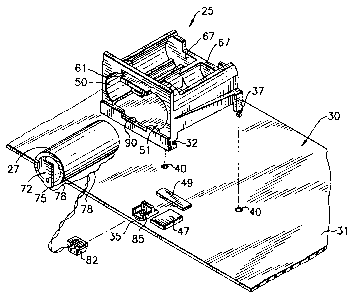
The battery holder 25 is provided with a combination
of mounting means for mounting to a printed circuit board
30. Although not illustrated in Fig. 3, the printed
circuit board typically includes a plurality of circuit
components mounted on one side 31, and electrical
connections between the various circuit components on
both sides thereof. The mounting means for mounting the
-5-

21~~~~
battery holder 25 to the printed circuit board 30
includes a channel 32 on a forward side of the battery
holder 25 which is configured to receive a side or edge
35 of the printed circuit board 30. On a rear side of
the battery holder 25 a pair of deformable fastening
means 37 are provided to be received in a pair of
apertures 40 formed in the printed circuit board for snap
fit engagement therebetween. As illustrated in Fig. 4,
when the battery holder 25 is mounted to the printed
circuit board 30, the forward edge 35 of the printed
circuit board is securely received in the channel 32, and
the deformable fastening means 37 are received in the
apertures 40 and engage the printed circuit board for
providing secure retention of the battery holder 25 on
the printed circuit board. The fastening means 32, 40
cooperate to hold the battery holder 25 in spaced
relation to the printed circuit board 30 so that a space
43 (Fig. 4) is provided therebetween. In this way,
various circuit components 47, 49 may be mounted on the
printed circuit board 30 between the printed circuit
board and the battery holder 25.
Referring again to Fig. 3, the battery holder 25
includes a pair of juxtaposed chambers 50, 51, each
chamber being configured to receive a battery 27. The
internal circumference of each chamber 50, 51 is slightly
larger than the external circumference of the battery 27
so that the battery is securely retained therein and the
movement of a battery 27 is extremely limited when
inserted in one of the chambers 50, 51. The battery
holder 25 is also provided with a retention clip 56 for
retaining batteries within the chambers 50, 51.
Referring also to Figs. 5 and 6, a resiliently
deformable arm 58 of the retention clip 56 is deformable
in response to a force applied by an operator for
insertion of a battery 27 within one of the chambers 50,
51. In Fig. 5, the retention clip 56 is shown in its
deformed or displaced position, with its normal or non-
-6-

21~~~~
displaced position being shown in phantom at 56a. In
Figs. 3, 4 and 6, the retention clip 56 is shown as
including an extension tab 61 for engagement with a
finger of an operator so that the retention clip may be
easily repositioned for insertion of a battery within a
chamber.
During insertion or removal of a battery within one
of the chambers 50, 51, a force is applied to the tab 61
in the direction of the arrow 59 of Fig. 5. Once the
l0 retention clip 56 is repositioned as shown at 56a in Fig.
5, the entrances to chambers 50, 51 are clear so that a
battery may be inserted within each chamber. In Fig. 5,
a battery is shown in phantom at 27a after being inserted
within the chamber 51 with the retention clip in its
displaced position 56a.
Referring to Figs. 3 and 6, when the retention clip
56 is returned to its normal position, a back surface 63
of the retention tab 61 engages a forward end of the
battery to thereby securely hold the battery within a
chamber. The distance between a back end 67 of each
channel 50, 51 and the back surface 63 of the retention
clip 56 is slightly greater than the axial length of a
battery 27 to thereby limit the actual movement of the
battery 27 when positioned within a chamber 50, 51.
On either side of the battery 27, electrical contact
means 72 are mounted thereon for providing an electrical
contact with the battery. Attached to one end 75 of each
electrical contact means 72 is a conductor 78 for
providing an electrical path between the battery 27 and a
known type of connector 82. As illustrated in Fig. 3, a
male connector 82 is attached to the battery conductors
78, and a female connector 85 is mounted on the printed
circuit board. Upon engagement of the male connector 82
with the female connector 85 a complete circuit path is
provided between the battery 27 and the printed circuit
board 30. Various electrical connections (not shown) may
be provided between the female connector 85 mounted on
_7_

~1~~~~3
the printed circuit board and various circuit components
(not shown) mounted on the printed circuit board 30.
Referring again to Figs. 2 and 3, when the battery
holder 25 is mounted to the printed circuit board 30, a
cutout section 90 is provided in the front of the battery
holder 25 to thereby provide for the connection and
removal of the male connector 82 from the female
connector 85. Therefore, access is provided for
installation and removal of a battery from the battery
holder 25 without removal of the printed circuit board
from the housing 10.
Although the invention is illustrated with having a
single pair of connectors 82 and 85 for establishing a
connection between a single battery 27 and the printed
circuit board 30, additional connectors may be provided
on the printed circuit board for receiving additional
male connectors 82 attached to batteries if more than one
battery is required for providing power to the printed
circuit board 30. Alternatively, several batteries may
be interconnected to a single male connector for
connection to the female connector 85 mounted on the
printed circuit board 30.
Although the invention is illustrated herein as
having circular chambers 50, 51 for receiving a cylinder
shaped battery 27, it will be understood by those skilled
in the art that the invention will work equally as well
with various shaped chambers for receiving similarly
shaped batteries, e.g., a rectangular or square shaped
chamber for receiving a rectangular or square shaped
battery. Additionally, although the invention is shown
and illustrated as including two chambers within the
battery holder 25, it will be understood by those skilled
in the art that the invention would work equally as well
with a single chamber in the battery holder.
Additionally, it is apparent that the invention would
also work equally as well with more than two chambers
provided for receiving batteries in those instances where
_g_

21~~'~(~~'~
more than two batteries are required for powering the
printed circuit board 30. In this case, for each N
chambers provided, where N is an integer, N-1 retention
clips would be provided, with a retention clip being
positioned between each pair of juxtaposed batteries.
This relationship works for all number of N batteries
with the exception of one chamber being provided, in
which case at least one retention clip would be required
for retaining the battery within the chamber.
Although the invention has been described and
illustrated with respect to exemplary embodiments
thereof, it should be understood by those skilled in the
art that the foregoing and various other changes in the
omissions may be made therein and thereto without
departing from the spirit and scope of the present
invention.
What is claimed is:
-9-

Dessin représentatif
Une figure unique qui représente un dessin illustrant l'invention.
États administratifs

2024-08-01 : Dans le cadre de la transition vers les Brevets de nouvelle génération (BNG), la base de données sur les brevets canadiens (BDBC) contient désormais un Historique d'événement plus détaillé, qui reproduit le Journal des événements de notre nouvelle solution interne.

Veuillez noter que les événements débutant par « Inactive : » se réfèrent à des événements qui ne sont plus utilisés dans notre nouvelle solution interne.

Pour une meilleure compréhension de l'état de la demande ou brevet qui figure sur cette page, la rubrique Mise en garde , et les descriptions de Brevet , Historique d'événement , Taxes périodiques et Historique des paiements devraient être consultées.

Historique d'événement

Description Date
Inactive : CIB désactivée 2011-07-27
Inactive : CIB de MCD 2006-03-11
Le délai pour l'annulation est expiré 2004-09-20
Lettre envoyée 2003-09-22
Accordé par délivrance 2002-12-31
Inactive : Page couverture publiée 2002-12-30
Préoctroi 2002-10-10
Inactive : Taxe finale reçue 2002-10-10
Inactive : Correspondance - Poursuite 2002-05-08
Inactive : Correspondance - Poursuite 2002-05-07
Un avis d'acceptation est envoyé 2002-05-03
Lettre envoyée 2002-05-03
Inactive : Correspondance - Poursuite 2002-04-30
Inactive : Correspondance - Poursuite 2002-04-26
Inactive : Approuvée aux fins d'acceptation (AFA) 2002-04-23
Lettre envoyée 1999-09-14
Inactive : Renseign. sur l'état - Complets dès date d'ent. journ. 1999-04-14
Inactive : Dem. traitée sur TS dès date d'ent. journal 1999-04-14
Modification reçue - modification volontaire 1999-03-29
Exigences pour une requête d'examen - jugée conforme 1999-03-23
Toutes les exigences pour l'examen - jugée conforme 1999-03-23
Inactive : Transferts multiples 1997-12-10
Demande publiée (accessible au public) 1996-03-22

Historique d'abandonnement

Il n'y a pas d'historique d'abandonnement

Taxes périodiques

Le dernier paiement a été reçu le 2002-06-19

Avis : Si le paiement en totalité n'a pas été reçu au plus tard à la date indiquée, une taxe supplémentaire peut être imposée, soit une des taxes suivantes :

  • taxe de rétablissement ;
  • taxe pour paiement en souffrance ; ou
  • taxe additionnelle pour le renversement d'une péremption réputée.

Les taxes sur les brevets sont ajustées au 1er janvier de chaque année. Les montants ci-dessus sont les montants actuels s'ils sont reçus au plus tard le 31 décembre de l'année en cours.
Veuillez vous référer à la page web des taxes sur les brevets de l'OPIC pour voir tous les montants actuels des taxes.

Historique des taxes

Type de taxes Anniversaire Échéance Date payée
TM (demande, 2e anniv.) - générale 02 1997-09-22 1997-06-18
Enregistrement d'un document 1997-12-10
TM (demande, 3e anniv.) - générale 03 1998-09-21 1998-06-25
Requête d'examen - générale 1999-03-23
TM (demande, 4e anniv.) - générale 04 1999-09-20 1999-06-17
TM (demande, 5e anniv.) - générale 05 2000-09-20 2000-06-27
TM (demande, 6e anniv.) - générale 06 2001-09-20 2001-06-22
TM (demande, 7e anniv.) - générale 07 2002-09-20 2002-06-19
Taxe finale - générale 2002-10-10
Titulaires au dossier

Les titulaires actuels et antérieures au dossier sont affichés en ordre alphabétique.

Titulaires actuels au dossier
SCHNEIDER AUTOMATION INC.
AEG SCHNEIDER AUTOMATION, INC.
Titulaires antérieures au dossier
TIMOTHY J. BYRD
Les propriétaires antérieurs qui ne figurent pas dans la liste des « Propriétaires au dossier » apparaîtront dans d'autres documents au dossier.
Documents

Pour visionner les fichiers sélectionnés, entrer le code reCAPTCHA :


Pour visualiser une image, cliquer sur un lien dans la colonne description du document. Pour télécharger l'image (les images), cliquer l'une ou plusieurs cases à cocher dans la première colonne et ensuite cliquer sur le bouton "Télécharger sélection en format PDF (archive Zip)" ou le bouton "Télécharger sélection (en un fichier PDF fusionné)".

Liste des documents de brevet publiés et non publiés sur la BDBC .

Si vous avez des difficultés à accéder au contenu, veuillez communiquer avec le Centre de services à la clientèle au 1-866-997-1936, ou envoyer un courriel au Centre de service à la clientèle de l'OPIC.


Description du
Document 
Date
(aaaa-mm-jj) 
Nombre de pages   Taille de l'image (Ko) 
Dessin représentatif 2002-04-25 1 21
Dessin représentatif 1998-05-05 1 31
Revendications 1996-03-21 5 207
Description 1996-03-21 9 404
Description 1996-03-21 1 26
Dessins 1996-03-21 2 89
Revendications 1999-03-28 5 223
Dessins 1999-03-28 2 85
Description 1999-03-28 10 415
Abrégé 1999-03-28 1 28
Accusé de réception de la requête d'examen 1999-09-13 1 179
Avis du commissaire - Demande jugée acceptable 2002-05-02 1 165
Avis concernant la taxe de maintien 2003-11-16 1 173
Correspondance 2002-10-09 1 37