Note : Les descriptions sont présentées dans la langue officielle dans laquelle elles ont été soumises.
- CA 02159023 2000-04-26
., _
- 1 -
DIE CAST VENT BLOCK
Thiea invention generally relates to die
casting vacuum valve systems and, more particularly, to
die casting vacuum valve systems with vent blocks.
Traditionally, in vacuum die casting, it is
recommended that air and gases be removed from the
casting cavity. prior to injection of nay molten
material. Evacuation of the cavity is generally
accomplished by a venting device coupled with the
cavity and mo7.d dies. Maximum evacuation results in
optimum flow of molten material into the cavity which,
in turn, eliminates imperfections in the surface finish
and provides f:or improved casting.
The present invention relates to a new and
improved die east vent block which provides additional
protection to the venting passageway is a die casting
vacuum valve system. These inventive die cast vent
blocks are included in a die cast vacuum valve system
adapted to be coupled with a casting die pair or
integrated with the die blocks in a vacuum casting
apparatus. Typically, a vacuum casting apparatus has
an electrical or mechanical shut-off member which
prevents the flow of molten material past a certain
point. In the: present invention, if an electrical or
mechanical malfunction occurs and the shut-off member
does not shift: to the closed position to prevent the
flov~r of molten: material, the molten material will flow
into the die east vent blocks is a serpentine, tortuous
. CA 02159023 2000-04-26
- 2 -
path, cool and eventually stop. Thus, the present
invention provides a die cast vent block which
efficiently and effectively prevents the flow of molten
material into a venting passageway when an electrical
or mechanical shut-off member malfunctions, enabling
the die cast vacuum valve. system to operate more
efficiently, producing improved castings.
. Vent blocks are normally ineffective during
production by themselves since there is no way to
remove molten material particles or flash after each
shot of molten material. Therefore, it is a further
object of the present invention to provide a die cast
vent block wh:Lch requires a~minimum amount of time and
effort to maintain, enabling machine shut-dower time to
be limited.
The above is only one example, and a die cast
vent block in accordance with the present invention may
have many varied uses. These, and other objects and
advantages of the iavention~over the existing prior art
forms, will be:come apparent from a reading of the
following brief description in accordance with the
attached drawjLngs .
FIG.. 1 is a cross-sectional view of a die
cast vacuum valve system in accordance with the present
invention;
FIG. 2 is a cross-sectional view of the die
cast vent blocks of FIG. l;
FIG. 3 is a detailed plan view of the ejector
vent block of FIG. 2 showing elongated elliptical lands
and grooves;
FIG. 4 is a detailed plan view of the cover
vent block of FIG. 2 showing elongated elliptical lands
and grooves;
FIG. 5 illustrates a cross-sectional view of
an alternate embodiment of the die cast vent blocks in
accordance with the present invention; and
CA 02159023 2000-04-26
- _ 3 _
FIG. 6 illustrates a cross-sectional view of
a second alte~raate embodiment of the die cast vent
blocks in accordance with the present invention.
Referring now to the drawings, there.is
depicted a die cast vacuum valve system embodying the
concept of the. present invention. The die cast vacuum
valve system :LO is associated with a die set including
a cover die 12 and ejector die 14 ae illustrated
partially in phantom in FIG. 1. Cover die 12 and
ejector die 1~6 include and form the mold cavity (not
shown) . ~ The cavity (not shown) is separated by a
parting line 7L6. Adjacent surfaces 13 and 15 define
parting line T~.6.
The vacuum valve system 10 has two halves, a
cover vent block 18, connected to the cover die 12, and
an ejector vent block 20, coupled with the ejector die
14. These two vent blocks 18 and 20 form the housing
of the vacuum valve system 10. As can be seen is FIG.
1, the cover vent block 18 and ejector vent block 20
are generally rectangular. Optionally, cover vent
block 18 and ejector vent block 20 may be built into
cover die 12 send ejector die 14, respectively, aad a
unitary part thereof. Cover vent block 18 and ejector
vent block 20 will have a gas flow rate of 0.105 in.2
(0.030 in. deep x'3.500 in. wide = 0.105 in.2).
The ejector vent block 20 includes a slot or
notch 22 eaabl.ing an overflow runner to be formed
therein when t:he cavity is filled with molten material.
The ejector vent block 20 also includes an enlarged
counter-sunk bore 24 which houses the shut-off piston
26 and the shut-off piston assembly 28, a passageway 30
and a bore 32 which provides passage for the shut-off
piston 26. A bushing 34 is located in the bore 32.
The ejector vent block 20 also includes an overflow
trough 36 which provides an access area if the shut-off
piston 26 does; not pinch off the flow of molten
4 _ 2159023
material along slot 22 in time. Thus, ejector vent
block 20 provides an area for overflow of molten
material. A hydraulic cylinder assembly 38 (not shows)
or the like, moves the shut-off piston 26 within
bore 32.
The cover vent block 18 includes a central
bore 40 which houses cushion piston 42 and cushion
piston assembly 44. The cushion piston 42 has a
portion 46 that extends beyond the surface 13 of the
cover vent block 18 as seen in FIG. 1. This portion 46
of cushion piston 42 is in its first resting or
original position extending beyond the surface 13 of
the cover vent block 18 when the cushion piston 42 is
loaded and secured in cover vent block 18. Cushion
piston 42 is contacted by the shut-off piston 26 when
the shut-off piston 26 is closed in response to molten
material entering the cavity. The cushion piston 42
cushions the shut-off piston 26 as it tightly clamps
and closes the parting line~l6 at the slot 22. As the
shut-off piston 26 actuates upward, the cushion piston
42 moves upward such that the portion 46 of the cushion
piston 42 becomes flush with the surface 13 of the
cover vent block 18. At this time, the shut-off piston
26 contacts the surface 13 of the cover vent block 18
peripherally about the cushion piston 42 sealing the
shut-off piston 26 with the cover vent block 18 to
terminate the flow of molten material through slot 22.
Once the shut-off piston 26 is removed from contact
with the cushion piston 42, the cushion piston 42
returns to its normal or original position where
portion 46 of the cushion piston 42 extends from the
surface 13 of the cover vent block 18.
Vacuum valve system 10 also includes a vacuum
port 48 opening into a venting passage 50. Vacuum port
48 and venting passage 50 are disposed at parting line
16. A vacuum system (not shown) is adapted to be
coupled with the vacuum port 48 to draw air and fluid
CA 02159023 2000-04-26
- _ 5 _
from the cavity through vacuum valve system 10. The
vacuum is drawn through vacuum valve system 10 via slot
22, overflow trough 36 and venting passage 50 while the
shut-off piston 26 is out of contact with the cushion
piston 42.
The piston shut-off assembly 28, hydraulic
cylinder assembly 38 and cushion piston assembly 44 may
be like that disclosed in U.S. Patents No. 5,101,882,
5,538,069 and 5,540,272.
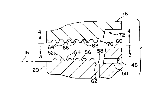
As shown in FIG. 1 and FIG. 2, ejector vent
block 20 further includes a set of leads 52 and grooves
54. Lands 52 and trapezoidal grooves 54 are disposed
above parting line 16. Lower surfaces 56 of the
trapezoidal grooves 54 are disposed at parting line 16.
Lands 52 and lower surfaces 56 of trapezoidal grooves
54 are parallel to each other and parting line 16. As
shown in FIG. 3, lands 52 and trapezoidal grooves 54
are adjacent, alternate and extend substantially across
ejector vent block 20 as elongated ellipses.
Ejector vent block 20 also includes slot 58
and plug 60 which are in lateral communication with
each other, and lands 52 and trapezoidal grooves 54.
Slot 58 extends downward and is disposed below parting
line 16, and h.as a lower surface 62. Lower surface 62
of slot 58 is ;parallel to partiag line 16, and lands 52
and lower surfaces 56 of trapezoidal grooves 54. Plug
60 extends upward and is disposed above parting
line 16.
As sJhown in FIG. 1 and FIG. 2, cover vent
block 18 also ;includes a complimentary set of lands 64
and grooves 66. Lands 64 are disposed at parting line
16 when the digs pair is closed, while trapezoidal
grooves 66 are disposed above parting line 16. Upper
surfaces 68 of trapezoidal grooves 66 are also disposed
2159023
- 6 -
above parting lice 16. Lands 64 and upper surfaces 68
of trapezoidal grooves 66 are parallel to each other
and parting line 16. As shown in FIG. 4, lands 64 and
trapezoidal grooves 66 are adjacent, alternate and
extend substantially across cover vent block 18 as
elongated ellipses.
Cover vent block 18 also includes key 70 and
slot 72 which are in lateral communication with each
other, and lands 64 and trapezoidal grooves 66. Rey 70
and slot 72 both extend inward away from parting
line 16.
A heat sensor may also be associated with
vacuum valve system 10 is order to detect heat in the
material flow areas or some type of malfunction.
Should excess heat in the material flaw areas be
detected or some type of malfunction exist, the machine
will shut-down. During this shut-down time, the
machine.operator will be allowed to clean cover vent
block 18 and ejector vent block 20 before the next shot
of molten material is introduced. A complete
explanation of the vacuum casting process is thoroughly
shown and disclosed in U.S. Patent No. 5,101,882.
In operation, if for any reason there is an
electrical or mechanical malfunction and the shut-off
piston 26 and the cushion piston 42 fail to seal at
parting line 16, enabling the flow of molten material
to continue past this point, the molten material will
flow into the set of lands 52 and grooves 54 of ejector
vent block 20 and the complimentary set of lands 64 and
grooves 66 of cover vent block 18. This will force the
molten material to flow in a serpentine, tortuous path,
enabling the molten material to cool, solidify and
stop. As cover vent block 18 and ejector vent block 20
come together, lands 52 and grooves 54 of ejector vent
block 20 mate with lands 64 and grooves 66 of cover
vent block 18. Lands 52 engage upper surfaces 68 of
trapezoidal grooves 66 while lower surfaces 56 of
- 7 - 2 ~ 5023
trapezoidal grooves 54 engage lands 64.
After the mating vent blocks cool, solidify,
stop and prevent the further flow of molten material,
the die cast apparatus will complete its cycle, open
and eject the formed casting, which still should be in
good condition. While the die cast apparatus remains
shut-down until the malfunction is solved, the operator
can clean and ready cover vent block 18 and ejector
vent block 20 for the next shot of molten material.
Shown in FIG. 5 is a second embodiment of die
cast vent blocks 74 in accordance with the present
invention. Like reference numbers will be used to
identify like components. In this embodiment. ejector
vent block 20 includes a set of lands 76 and grooves
78. Lands 76 are offset with respect to parting line
16. Trapezoidal grooves 78 have lower surfaces 80.
Lower surfaces 80 of trapezoidal grooves 78 are offset
with respect to parting line 16. Lands 76 and lower
surfaces 80 of trapezoidal grooves 78 are parallel to
each other and parting line 16. The offset may be
above or below parting line 16.
Moreover, in this embodiment, cover vent
block 18 includes a complimentary set of lands 82 and
grooves 84. Lands 82 are offset with respect to
parting line 16. Trapezoidal grooves 84 have upper
surfaces 86. Upper surfaces 86 of trapezoidal grooves
84 are offset with respect to parting line 16. Lands
82 and upper surfaces 86 of trapezoidal grooves 84 are
parallel to each other and parting line 16. The offset
may be above or below parting line 16.
Lands 76 and grooves 78 of ejector vent block
20 mate with lands 82 and grooves 84 of cover vent
block 18. Lands 76 engage upper surfaces 86 of
trapezoidal grooves 84 while lower surfaces 80 of
trapezoidal grooves 78 engage lands 82. Again, these
mating vent blocks force molten material to flow in a
serpentine, tortuous path, enabling the molten material
_ g _
2159023
to cool, solidify and stop.
This embodiment results in a more
restrictive, efficient and effective die cast vent
block apparatus thereby enhancing the performance of
this device. The die cast vacuum valve system of this
embodiment operates substantially the same as that of
the die cast vacuum valve system 10 previously
described.
Shown in FIG. 6 is a third embodiment of die
cast vent blocks 88 in accordance with the present
invention. Like reference numbers will again be used
to identify like components. In this embodiment, cover
vent block 18 and ejector vent block 20 include lands
and grooves as previously described and shown in FIGS.
1-4. The mating lands and grooves shown in FIG. 6 are
disposed above parting line 16.
Moreover, in this embodiment, ejector vent
block 20 includes vacuum port 48 and venting passage
50, which are both disposed below parting line 16.
Venting passage 50 is in communication with and opens
into a second venting passage 90. Second venting
passage 90 is perpendicular to venting passage 50 and
disposed in cover vent block 18 and ejector vent
block 20.
The die cast vacuum valve system of this
embodiment also operates substantially the same as that
of the die cast vacuum valve system 10 previously
described.
While the above detailed descriptions
describe the preferred embodiment of the present
invention, it will be understood that the present
invention is susceptible to modification, variation and
alteration without deviating from the scope and fair
meaning of the subjoined claims.