Note : Les descriptions sont présentées dans la langue officielle dans laquelle elles ont été soumises.
WO 94/24326
PCT/GB94/00798
- 1 -
This invention relates to a method of making
. a hollow body for a pressure container, using an
aluminium alloy of the 7000 series. The method is
particularly suitable for the manufacture of high
pressure gas cylinders. There is currently competition
between manufacturers of pressurised gas cylinders in
aluminium, steel and composite materials.
Basic requirements of materials for use in
pressurised gas containment systems include: providing
adequate fabricability to allow manufacture of the
system and the capability to provide adequate strength,
ductility, toughness, corrosion resistance, and
resistance to all forms of time-dependence degradation
of mechanical properties in the final product.
In the past, these requirements have
restricted the use of aluminium alloys in commercial
gas cylinders to those with peak strengths below about
450 MPa. An ill-fated attempt to exceed this strength
level was made in the early 1970s, when a 7000 series
aluminium alloy gas cylinder was introduced into the
marketplace and resulted in the recall of all cylinders
due to severe stress corrosion cracking initiating
after limited service life that eventually would have
led to catastrophic failures.
U.S. Patent 4,439,246 (Gerzat) describes a
method of making pressurised gas cylinders from 7475
~ alloy. A billet of the alloy was homogenised for 12
hours at 465°C; hot (or alternatively cold) extruded;
necked; solution annealed and quenched; and finally
aged by the two step tempering type T73 treatment.
European Patent specification 257 167
CA 02159193 2005-10-07
2 -
(Gerzat) reports that the products (of the aforesaid
U.S. patent) were found to be unsuitable after
extensive testing, despite their very high level of
fracture toughness, their good mechanical strength and
excellent stress corrosion resistance in the T73
condition. The problem is solved, according to the
European patent specification, by use of an alloy
comprising 6.25 - 8.0% Zn; 1.2 - 2.2% Mg; 1.7 -
2.8% Cu; 0.15 - 0.28% Cr; and Fe + Si preferably
< 0.25%. As-cast billets of this composition are
subjected to hot backward extrusion; drawing;
necking; solution heat treating and quenching; and
precipitation heat treating to a variety of over-aged
conditions.
There is a need for pressurised gas cylinders
with a higher strength to weight ratio, and in which
any failure is preferably confined to the cylindrical
part and does not spread to or occur at either the base
or the shoulder.
The present invention provides a method of
making a hollow body for a pressure container, from an
aluminium alloy of composition (in wt %)
Zn 5.0 - ?.0
Mg 1.5 - 3.0
Cu 1.0 - 2.7
Recrystallisation inhibitor 0.05 - 0.4
Fe up to 0.30
Si up to 0.15
other impurities up to 0.05 each and 0.15
. in total,
A1 balance
said recrystallisation inhibitor being selected
from Cr, Zr, Mn, V, Hf or Sc ,
said method comprising
(i) homogenising the alloy, said homogenisation
consisting of raising the temperature in the range
470 to 488°C for a time sufficient to reduce the
volume fraction of S phase (CuMgAl2) to below 0.20,
(ii) extruding the alloy,
CA 02159193 2005-10-07
- 3 -
(iii) forming the extrusion into the shape of the
desired hollow body, and
(iv) over-ageing the hollow body.
Preferably the alloy has the following
composition:
Zn 5.0 - 7.C
Mg 1.5 - 2.5
Cu 1.8 - 2.2
Cr and/or Zr 0.10 - 0.25
Fe up to 0.15
Si up to 0.08
The Zn concentration is 5 - 7 %. If the Zn
concentration is too low, the alloy lacks the strength
necessary to permit overageing. If the Zn content is
too high, the alloy is difficult to cast by direct
chill casting techniques, and the cast product is
brittle and difficult to age in order to increase
toughness. Alloys with higher Zn contents require
higher extrusion pressures, and thus increased
extrusion press costs and maintenance.
Mg acts in combination with Zn to increase
hardness.
The Cu content is 1.0 - 2.7%, preferably ~.8
- 2.2%. Cu is required to permit overageing to give
stress corrosion resistance. The formation of an
undesired S-phase (of composition CuMgAl2) increases
with increasing Cu content, but can be dealt with by
homogenisation of the cast ingot (as discussed below).
Cr and/or Zr is used as a recrystallisation
inhibitor during solution heat treatment. An
excessively high concentration of this component would
spoil the fracture toughness. Alloys containing Cr,
when compared to corresponding alloys containing Zr:
require less critical control of homogenisation
conditions, and lower extrusion pressures whicr reduce
the problem of lubrication; and are accordingly
preferred. Pressure containers con'a~:.ir.c Cr as a
WO 94/24326 ~ ~, ~ ~ ~ c~.~ PCT/GB94/00798
- 4 -
recrystallisation inhibitor have the additional
advantage of exce~lerit resistance to sustained load
cracking. Other transition metal recrystallisation ,
inhibitors such as Mn, V, Hf, Sc are possible but non-
preferred alternatives which can be used alone or in ,
combination with each other and/or with Cr and/or Zr.
Fe and Si are normally present in A1 alloys.
But their presence in these alloys is not desired, and
their concentration needs to be controlled. Alloys
containing excessively high concentrations of Fe and Si
are known to have reduced toughness and also reduced
corrosion resistance. Fe tends to precipitate in
combination with Cu and A1 thereby reducing the amount
of S phase present. However, the Fe bearing
precipitates do not redissolve during homogenisation
and their presence reduces fracture toughness.
Cylinders having excellent fracture and burst
characteristics are obtained when the Fe content is no
more than 0.10.
Other known components, e.g. B, may be
incorporated in the alloy in usual amounts. Be may be
used (where permitted) for oxidation control. Ti may
be added as a grain refiner to provide a preferred
concentration of 0.02 - 0.07 in the final product.
Apart from incidental impurities, the balance is A1 of
at least commercial purity, although high purity 99.9
A1 may be preferred.
In the following description of the
fabrication procedure according to this invention, the
steps of homogenising the cast ingot; extrusion; and
final ageing, are of particular importance.
An alloy of the desired composition is cast,
preferably by direct chill casting although spray
deposition (WO 91/14011) is possible for alloys with
high solute levels. The melt may optionally be
filtered and degassed prior to casting. The cast
WO 94124326 PCT/GB94/00798
- 5 -
billet is then stress relieved and homogenised, if
necessary to bring the volume fraction of S phase to a
value below 1.0~. Homogenisation may not be necessary
for spray deposited alloys.
Figure 1 is an isothermal section through a
v
phase diagram taken at 460'C of a DC cast A1 alloy
containing 6 wt ~ Zn and various concentrations of Cu
and Mg.
Referring to Figure 1, the rectangular box 1
represents the 7075 alloy; box 2 represents alloys
according to this invention; and box 3 represents
preferred alloys according to this invention. The
phase field in the bottom left hand corner of the
diagram marked A1 denotes compositions where the matrix
contains A1 with all of the Zn, Cu, Mg in solution.
The field marked A1S contains S-phase precipitate
(composition CuMgAl2) in an A1 alloy matrix. (See Met.
Trans., Vol 9a, Aug 1978, p 1087-1100). The other
fields contain other phases not important in the
present context. The compositions of the three marked
boxes straddle the A1/A1S boundary, and the same is
true of the compositions of the two above Gerzat
patents (which have not been shown to avoid confusing
the diagram). Segregation of elements in the as-cast
metal results in the presence of S phase precipitate in
all of the unhomogenised alloys. Higher Zn levels
(above 6~) tend to reduce the A1S field giving a
slightly smaller amount of S phase. Higher
temperatures (above 460'C) tend to reduce the A1S
field.
During homogenisation, the excess S phase
' dissolves, but this is a very slow process at low
homogenising temperatures. Most of the S phase is
' dissolved after 12 hours at 475'C, but after the same
time at the lower temperature of 465'C a substantial
proportion of this phase remains undissolved.
WO 94/24326 PCT/GB94/00798
- 6 -
s
F . '
Homogenising conditions depend to a small extent on
billet size. These figures relate to 229 mm diameter
ingot. Larger billet would require somewhat higher
temperatures and/or longer holding times.
After homogenisation, dissolved S phase does not re-
precipitate to any significant degree on air cooling to
room temperature.
The presence of S phase reduces the fracture
toughness of the alloy. Figures obtained on 7150 alloy
plate suggest that samples containing 0.25 volume ~ of
S phase have an average fracture toughness of
60 MNm-3/2, while samples with 0.15 volume ~ of S phase
have an average plane stress (Kapp) fracture toughness
of 75 MNm-3/2.
For the above reason, it is a critical
feature of the invention that the ingot has a low
volume fraction of S phase, e.g. by having been
homogenised at a temperature of at least 470'C and for
a time sufficient to reduce the volume fraction of S
phase to a value below 1.0~. Preferably the
homogenisation temperature is about 475'C. Liquation
of the S phase takes place at 488'C. Preferably the
heating rate at temperatures above 460'C is no more
than 10'/hour, and above 475'C is no more than 3'/hour,
so as to avoid the risk of undesired liquation.
The ingot is held at homogenising temperature
for a time to reduce the S phase to a desired low
level, usually below 0.2 volume, preferably below 0.1
volume ~ and desirably approaching zero. Preferably
the ingot is held at homogenising temperature for at
least 2 hours, e.g. 12 hours, with longer times
required at lower temperatures. '
After homogenising, the ingot may be air
cooled to room temperature. Cooling is preferably '
effected at a controlled rate below 200'C/hour.
Preferably, cooling is interrupted for 1 to 48 hours at
WO 94124326 PCT/GB94/00798
a hold temperature in the range 200-400°C; or cooling
may be continuous at a rate of about 10'C to 100'C per
. hour through this temperature range. These conditions
may reduce the press loads required for extrusion.
These homogenising schedules are designed to
ensure that substantially no S phase remains in the
ingot, thus improving the fracture toughness properties
of the extruded product; and that the ingot is in the
softest possible state, thus minimising the extrusion
pressure required.
The homogenised ingot may be scalped to
remove some or all of the shell and all the shuts, and
is then cut up into billets for extrusion.
Although hot extrusion according to the
invention is possible, cold or warm extrusion is
preferred as being a lower cost procedure. Cold or
warm extrusion may also give rise to an extrudate
having a better combination of strength and toughness
properties. Warm extrusion is typically performed with
a starting billet temperature at 100 - 250'C to avoid
hot shortness. Cold extrusion is typically performed
with a starting billet temperature at below 100'C e.g.
at ambient temperature. The preferred technique is
backward extrusion. This technique involves the use of
a recess, generally cylindrical, with parallel side
walls, and a ram to enter the recess, dimensioned to
leave a gap between itself and the side walls equal to
the desired thickness of the extrudate. An extrusion
billet is positioned in the recess. The ram is driven
into the billet and effects extrusion of the desired
hollow body in a backwards direction. The forward
motion of the ram stops at a distance from the bottom
of the recess equal to the desired thickness of the
base of the extruded hollow body. Extrusion speed, the
speed with which the extrudate exits from the recess,
is not critical but is typically in the range 50 -
WO 94/24326 PCT/GB94/00798
_ 8 _
.t
500 cm/min. Lubrication can substantially reduce the
extrusion pressure required.
The initial extrudate is cup-shaped, with a _
base, parallel side walls and an open top. The top is
squared off and heated, typically induction heated to
350 - 450'C, prior to the formation of a neck by
swaging or spinning. The resulting hollow body is
solution heat treated. Conditions are not critical but
may typically be 15 - 90 minutes at 475°C. Solution
heat treatment is followed by quenching, generally into
cold water.
After solution heat treatment and quenching,
the hollow body is aged. The alloy composition has
been chosen such that the peak aged strength is
substantially higher than necessary, and this enables
the body to be overaged to an extent to develop desired
properties, particularly fracture toughness and tear
resistance but.also fatigue strength, and slow crack
growth, creep, and stress corrosion resistance. Tear
resistance is defined as the energy required to keep a
crack growing and may be measured by the Paris toughness
index (Mechanics and Physics of Solids, Vol 26, 1978,
p 163). Ageing may preferably be effected to an extent
to reduce the mechanical properties (in comparison with
a peak aged product) by 10 or 15 - 30~ e.g. about 20~.
Various ageing temperatures, from 160 - 220'C, and
times, from 1 - 48 hours, may be necessary to achieve
this. Top ageing temperatures of 175 - 185'C for 2 -
24 hours are likely. These may be preceded by pre-
ageing at 80 - 150'C typically for 1 - 24 hours, and/or
followed by post-ageing at 80 - 150'C typically for 1 -
48 hours. Duplex and/or Triplex ageing may also '
improve tear resistance and yield strength.
It is known that homogenising treatments
reduce the amount of second phase particles present in
7000 series alloys, and that this can increase the
CA 02159193 2005-10-07
9
fracture toughness in products that have been hot worked e.g.
by hot rolling or hot extrusion. But most parts of the hollow
bodies produced according to the present invention are never
hot worked. In fact, there is a substantial difference
between the kind and extent of the work performed on different
parts of the hollow body:
- The walls, are heavily cold or warm worked during the
extrusion process.
- The base, by contrast, is less deformed and can retain
recognisable aspects of the cast and homogenised
microstructure.
- The neck of the hollow body is formed by hot working the
walls which themselves have been cold or warm worked; a
reverse of the usual procedure which involves hot working
followed by cold working.
These variations in working conditions produce profoundly
different microstructures in different parts of the hollow
body, and the method of this invention is a compromise
designed to generate adequate properties in all parts.
Similarly, overageing is known to increase fracture
toughness and stress corrosion resistance in products which
have been hot worked. But it was not obvious that a given
overageing treatment would be beneficial (or at least not
harmful) for all the different microstructures in the hollow
bodies made according to this invention.
Overageing can be effected by holding the hollow body at
a first elevated temperature and then at a second elevated
temperature lower than the first. Overageing can also be
effected by holding the hollow body at three elevated
temperatures in sequence, of which the second elevated
temperature is higher than the first and the third.
Reference is directed to the accompanying drawings in
which:-
CA 02159193 2005-10-07
9a
Figure 1 is a phase diagram, and has been referred to
above.
Figure 2 comprises two diagrams related to stress
corrosion cracking. Figure 2a) is a graph of crack length
against time, and shows crack extension in a double cantilever
beam fatigue pre-cracked specimen.
WO 94/24326 PCT/GB94/00798
- 10 -
Figure 2b) is a graph of crack velocity against stress
intensity calculated from the data in Figure 2a).
Figure.3-comprise~ two graphs a) and b)
corresponding to those in Figure 2. The graphs show
results obtained in laboratory air at 80'C as a measure
of sustained load cracking.
Figure 4 is a graph showing variation in
amount of S phase present with increasing time of
homogenisation at 475'C.
Figure 5 shows differential scanning
calorimetry traces on billet after homogenising for 12
hours at (A) 465'C and (B) 475'C.
Figure 6 is a graph showing relationship
between flow stress and ultimate tensile strength for
homogenised billets cooled in various ways.
Figure 7 is a graph of tear resistance and
yield strength for material held for up to six months
at 80'C after single or duplex ageing.
In a preliminary experiment, commercial 7150
alloy plate was overaged using a variety of heat
treatments to a yield strength of around 450 MPa and
then subjected to toughness testing. The test results
are set out in Table 1 and show that the alloy fracture
toughness and tearing resistance could be made adequate
for use in pressure vessel applications.
35
WO 94/24326 PCT/GB94/00798
- 1 1 -
+~
U
O
O _C_
U
ct~
O
e~
L
T
T
T
U O
._
O'
i
N~
O U
~ 'O
C
.~ cps
QV
O ~
Q~
d'
N .~
T
+r
L
WO 94/24326 ~ ~ ~ ~ ~ PCTlGB94/00798
- 12 -
Exam lp a 1
A 7000 series alloy with a nominal
composition of 6% Zn, 2% .Mg, 2% Cu was cast on a high
purity base (< 0.06%.Fe~and < 0.04% Si) A1 alloy in two
versions, one containing 0.2% Cr and the other 0.1% Zr.
Alloy composition is set out in Table 2.
Homogenisation conditions are set out in Table 3.
Billets were fabricated into pressurised gas cylinders
175 mm external diameter and 7.9 mm nominal wall
thickness, according to a schedule as described above
and corresponding to standard practice except that an
additional anneal was introduced prior to cylinder
heading via a hot swaging process. Mechanical
properties of the resulting pressurised gas cylinders
are set out in Table 4 for material taken from three
different locations. The chosen locations,
neck/shoulder, wall and base, cover the typical alloy
microstructures generated in an aluminium gas cylinder.
The results (Table 4) indicate that it is possible for
a given heat treatment to provide the balance of
properties needed for a safe cylinder despite there
being several alloy microstructures involved. Trial
cylinders (the Cr alloy formulation) have been
subjected to real-life atmospheric corrosion in a
marine environment and to laboratory corrosion testing
(galvanostatic) and conditions stipulated in the EEC
corrosion test for high pressure aluminium gas cylinders.
Results from all the corrosion tests indicate that the
cylinders under test have a corrosion resistance at
least as good as commercial 6000 series cylinders and
should therefore provide an adequate performance in
service. These results are believed surprising,
because 6000 series alloys such as 6061 and 6082 are
used unprotected in marine applications such as
helidecks on North Sea offshore oil platforms and are
considered to have a good corrosion resistance, whereas
WO 94124326 PCT/GB94/00798
- 13 -
M (~ C'~ M
CI~ ~ D O O Op ,'- N
. O 0 - . O O O T
: O O
:.::;:
:
.: O
.
;:~ O ~ O
: O O ~ O O
, o O O r ,"_
..
:::..:
,,
1'.. N
, , r O ~
, , O T Z
::v.:v O
>...
2
:~~' N F-
1.:': r~ N ~ N
~ o
:;_:~v O O o O p N a
::
.
::
0 0 ~ ~ cN0 0~0 C11 ~ ~ tn ..J o
J
N N T - ~ T T 1'~ T CV
_ N
v::~:4i:i.-,::4.O C ~ O~ CD O
~
;.:
. N N T T N ~ N N N d'
T N
.._
. O
a'v::~.
N ~. I~ N O O O
o
::_ . ~
:.;.,
...::.:-~C t0 t17 ~ (~ ~ ~ O
4
N . '~ ~ ~
~
_",
v ~ ct~ M fl
~--.: '
r"'
:: . . ,:.~ I~ : ...'
.: , ;
. . .
WO 94/24326 PCT/GB94/00798
- 14 -
U
0
0
r
.Q
VU N N
o ~ V ~ t0 C
o° i= t o .N
,,.., c
U ~ c~ c_ . c 'u O
tt~ ~ 3 ~S .~,,~ ~ O
_O ~ _0 O ct3
d~ O o ~ c~
r .c ~ o ~ V ~s ~ tL
~ ~ o.~ o'~ ~~ o~ T c
L C
w ~N v o .yU c,~ o
.._ .>_ O ~ . 'o .-. .cu °~ C U c~
L +~
.. U ~ o ~ o ~ o
U O o 0 o U >. ..''.~ U c~ t ~ o Cn
O o o O ~ U O N O O
c~ O N ctf U N ~ ,~ ~ c'~6
E.- ~ ~ U ~""' o .o ~~-. -a Z
~ '_d3 0 ~~ ~ ~ ~r ~C O O t~ ~ ~ ~ .C
M C ~ O ~ ~M O II L II ~
o ~ r ~ o .s~ r o y ~ cr...o
U C~ ~ ~L ~ ~ ~ L ~ N
Q N ~ °.~ Q u. ~ u~ .fl
~ .
. ~ .~ .
WO 94/24326 PCT/GB94/00798
- 15 -
;..; J
~ ,
~:
0 J
J ~ O
._ ::: a Q
Q: m ~ c~ V
o
y U Y ~
'' ~
vv:r:.:.J::~:::..r
...
U
~.c~
N c'~
0 d~ O
',.~:,v;~. d' -
; d
J ~ c~
:~
::y
'
: .-
''.
:y
.
~
.
C'~ ~ O
.
..
Z'
M ~ M ~- a
w
:::o ~
o::
:''
.
.
.
. T T T _ U
!
.
....:,
:
~
:
:
:
:
'
::
; ~
:
.
:
:::
:
:
::~v:>. .V c
':::::::: t~
. ~
~
:. N O T T
'-
'"': W ..
...
.
O I~ O
.,
~~.~9.~
WO 94/24326 PCT/GB94/00798
- 16 -
7000 series alloys, especially those containing above
0.5~ Cu, are generally regarded as having a poor
corrosion resistance~.in saline environments. .
Example 2 ,
In an attempt to reduce the extrusion press
loads required during cylinder shell fabrication, the
alloy composition for trial 2 was made slightly leaner
in Zn and Mg (Table 2) and the homogenisation practice
employed was further optimised (Table 3). This
approach proved successful with the required extrusion
press loads during cylinder shell production being
consistently lower than those associated with trial 1
(Table 5). Moreover as was observed in trial 1, the
loads for the Cr containing alloy were significantly
lower than for the Zr containing alloy. The importance
of this difference was clearly shown in trial 2, where
all 27 alloy billets of the Cr containing alloy
presented to the press were successfully extruded into
shells, whereas only half of the 18 Zr containing alloy
billets were extruded prior to the high tooling loads
leading to unacceptable distortion and a termination of
the trial. These problems could have been overcome by
warm extrusion or by using stronger tools or improved
lubrication.
On the basis of these observations, the Cr
based alloy is preferred as providing a) softer as-
homogenised material with a reduced tendency for
subsequent hardness increases via natural ageing which
thereby required lower press loads during extrusion,
and b) fabricated cylinders with higher toughness.
This preference for Cr-containing alloys is contrary to
a trend in high strength 7000 series alloy
developments, which has moved away from Cr containing
alloys such as 7075, 7175 and 7475, towards Zr
containing alloys e.g. 7050, 7150 and 7055, because the
WO 94/24326 PCT/GB94/00798
- 17 -
EXTRrISION PRESS LOADS DURING 7000 SERIES
CYLINDER TRIALS
Alloy Load
Cr-containing Alloy kN x 103
Trial 1 25.8
Trial 2 22.6 - 23.9
Trial 3 21.9 - 24.8
Load
Zr-containing Alloy kN x 103
Trial 1 26.8 - 27.7
Trial 2 24.5 - 26.5
30
WO 94/24326 ~ ~ ~ ~ PCT/GB94/00798
- 18 -
latter are less quench sensitive and are considered to
provide material with.~pofentially higher fracture
toughness.
After ageing for,5 hours at 180'C,
pressurised gas cylinders from this trial were ,
subjected to the EEC corrosion test, in which coupons
from shoulder, wall and base were exposed to acidified
chloride solution for 72 hours. All samples passed the
test. No intergranular corrosion was seen, only
crystallographic general attack evident.
The cylinders were also subjected to the EEC
stress corrosion cracking (SCC) test (EEC Specification
No. L300/41). Hoops from the cylinder wall were
subjected to both C-ring tensile and compressional
tests. The samples were loaded to a stress level of
0.2~ proof stress/1.3. The test environment was 3.5~
NaCl solution and exposure was alternate immersion
conditions (ASTM G44-75) for 30 days. The air
temperature was 27'C and the relative humidity 45~.
All samples tested completed the 30 day test period
without cracking, and hence are considered suitable, in
terms of resistance to SCC, for the manufacture of gas
cylinders.
Further work was completed to examine the SCC
susceptibility of the cylinder shoulder material using
even more severe test methods. Smooth tensile
samples were prepared from the shoulder material with a
circumferential orientation and subjected to a breaking
load test programme (E. L. Colvin and M. R. Emptage,
3p "The Breaking Load Method: Results and Statistical
Modification from the ASTM Interlaboratory Test
Program" in New Methods for Corrosion Testing Aluminium
Alloys, ASTM-STP 1134, V. S. Agarwala and G. M.
Ugiansky, Eds., American Society for Testing and
Materials, Philadelphia, 1992, pp 82-100). Samples
were tensile loaded to a specific stress level (see
~.~.~9~.9~
WO 94/24326 PCT/GB94/00798
- 19 -
Table 6) and subjected to a 3.5~ NaCl solution under
alternate immersion conditions (as discussed
previously). After 7 days the samples were removed
from the test environment, unloaded and pulled to
. 5 failure in a conventional tensile test. Any reduction
in the strength of the material would indicate a
susceptibility to SCC, however, even those samples
which were loaded to 90~ of the 0.2~ proof stress
displayed an excellent resistance to SCC, Table 6.
CYLINDER TEST APPLIED
STRESS
LEVEL
BREADING
IDENTIFICATION DURATION STRESS
LOAD (MPa>
(MPaj
A 0 / / 478/485
7 208 SERVICE PRESSURE 462/500
2 0 7 346 TEST PRESSURE 465/485
7 375 90% 0.2% PS 459/489
0 / / 479/499
7 208 SERVICE PRESSURE 482/484
2 5 7 346 TEST PRESSURE 468/491
7 375 90% 0.2% PS 472/472
30 The final column Table 6, referring to
in
'Breaking Load'
shows the results
of two independent
but nominally i.e. environment,
similar samples,
exposure time,
and applied
stress were
identical for
both samples
tested.
35 Stress corrosion cking in all the tests
cra
described above from smooth surfaces.
was initiated
WO 94/24326 PCT/GB94/00798
Fatigue pre-cracked fracture mechanics type compact
tension specimens taken from both cylinder bases and
shoulders, Trial 2 alloy, have been used to
characterise cylinder materials crack growth resistance
5 for cracks initiating from pre-existing sharp cracks. ,
For the chromium containing alloy cylinders, tests have
been conducted using two environments:
a) a chromate-inhibited acidified aqueous saline
environment at room temperature (2~ sodium chloride +
10 0.5~ sodium chromate acidified to a pH of 3.5 using
conc. HC1) (stress corrosion cracking) and
b) laboratory air at 80'C (sustained load
cracking).
Samples (identified as Top 3 in Figs. 2 and
15 3) were taken from the neck/shoulder region of a
cylinder and notched so as to orientate the crack in
the most susceptible direction. Further samples were
taken from the base of the cylinder (identified as Base
2 in Figs. 2 and 3) and notched in a radial direction
20 away from the centre.
In Figs. 2a) and 3a), the data is presented
in the form of crack growth as a function of time. In
Figs. 2b) and 3b), the crack growth rate data is
presented as a function of stress intensity factor.
The results for the Cr-containing alloy show that the
crack growth rates fall below 10-13 m/s for stress
intensity factors below 30 MNm-3/2 and therefore the
material from the chromium-containing alloy cylinders
is extremely resistant to crack propagation via either
stress corrosion cracking or sustained load cracking
(SLC). Sustained load cracking is a relatively
recently identified intergranular crack growth
mechanism for precipitate hardening aluminium alloys
(see Met. Trans. Vol 23A, pp 1679-1689, 1992).
2i~~~.~~
WO 94/24326 PCT/GB94/00798
- 21 -
example 3
On the basis of the information from the
. first two cylinder fabrication trials, a further trial
(trial 3) was designed. This employed two versions of
the Cr-containing 7000 series alloy, Table 2, which
were homogenised using one of two practices, Table 3.
All 47 billets presented to the extrusion press during
trial 3 were successfully extruded and fabricated into
gas cylinders with the same dimension as trials 1 and
2, i.e. 175 mm external diameter and 7.9 mm wall
thickness. As expected the extrusion press loads
increased with alloys Zn and Mg concentration, however
the absolute value for a given alloy composition was
lower in trial 3 than the two earlier trials. In
addition the press loads for the experimental alloys
were reduced when the homogenisation practice involved
step cooling from the soak temperature and/or a lower
extrusion ram speed during shell fabrication. The
extrusion pressures and as-homogenised mechanical
properties are reported in Table 7.
The pressurised gas cylinders were solution
heat treated at 475'C for one hour, cold water
quenched, and aged at 180'C for 4.5 hours, before being
subjected to various tests. Two rings and four equal
size bend strips were sectioned from each of six cylinders.
Samples 18.1 mm wide and 175 mm long, were taken from 6
cylinders (cylinders A-F in Table 8) and subjected to
bend tests. All samples bent around a mandrel with a
diameter of 47.1 mm, did so without cracking.
Six cylinders were subjected to tensile tests,
with the results set out in the following Table 8.
' Two cylinders were subjected to a burst test,
with the results set out in the following Table 9.
' Three cylinders were subjected to fatigue
tests at a fatigue test pressure of 343 Bar (34.3 MPa)
with the results set out in Table 10.
WO 94124326 PCT/GB94/00798
- 22 -
TABLE 7
EXTRUSION PRESS TONNAGES AND AS-HOMOGENISED MECHANICAL
PROPERTIES FOR 7000 SERIES. ALLOYS USED IN TRIAL 3
ALLOY HOMOGENISATIONTENSILE EXTRUSIONRAM
I.D. PROPERTIES
(AFTER
(See Table(See Table HOMOGENISATION) PRESSURESPEED
2) 3)
3
MPa x (mm/s)
10
O.ZX UTS ELONGN
PS
(MPa) (MPa) (X)
FAST 102 237 18.6 1214 46.6
(.12.4)
1152 10.6
(=12.4)
A
(5.6 Zn) SLOW 93 211 14.0 1177 46.6
(+37.2)
1144 14.8
(14.3)
20
FAST 104 240 16.9 1227 46.6
(_=12.4)
1198 14.8
(t14.3)
B
(6.0 Zn) SLOW 96 222 16.2 1202 46.6
(12.4)
2 5 1115 14.8
(=21.5)
35
WO 94/24326 PCT/GB94/00798
- 23 -
CYLINDER HOMOGENISATION YIELD ULTIMATE ELONGATION
STRENGTH TENSILE
(MPaj STRENGTH
(MPa)
A FAST 435 496 14.5
SLOW 429 490 15.0
SLOW 435 500 13.8
D FAST 436 500 13.0
20
30
WO 94/24326 PCT/GB94/00798
CYLINDER, HOMOGENISATIONEX'I?RUSIONHEADINGBURST FAILURE
SPEED SPEED PRESSURE MODE
(mm/s) (mm/s) (MPa)
G SLOW 14.8 31.8 51.7 CENTER
S/W
(SLOW) (FAST)
H FAST 14.8 10.6 49.7 LOWER
S/W
(SLOW) (SLOW)
TABLE 10
2 CYLINDER HOMOGENISATION EXTRUSION HEADING N0. OF
O
SPEED SPEED CYCLES
(mm/s) (mm/s) TO
FAILURE
L FAST 46.6 31.8 4040
M FAST 10.6 31.8 4801
N FAST 14.8 21.2 4888
- 24 -
TABLE 9
,.
WO 94!24326 PCT/GB94/00798
- 25 -
~xamole 4
Homocreni si nq, Fracti ~p
The compositions of the alloys used in this
work are as shown in Table 11:
TABLE 11
Alloy Si Fe Cu Mn Mg Cr Ti Zn B
I 0.06 0.09 2.060.003 2.04 0.20 0.024 5.99 -
II 0.04 0.06 1.950.003 1.91 0.20 0.028 5.87 0.001
Samples from extrusion billet of alloy I
having diameters up to 300 mm were examined by
Differential Scanning Calorimetry (DSC) to determine
the amount of S phase after homogenising at 465 or
475'C for times up to 12 hours. It can be seen from
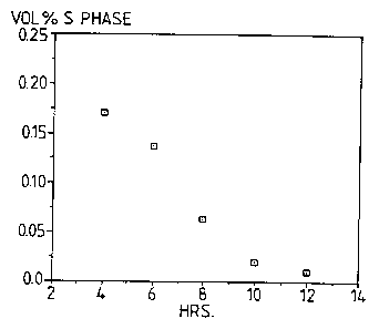
Figure 4 that times in excess of 7 hours at 475'C would
reduce S phase concentration to < 0.1$ by volume, while
12 hours at 475'C would reduce S phase to almost zero.
Figure 5 is a plot produced by (DSC)
comparing two billets homogenised for 12 hours at 475
and 12 hours at 465'C respectively. The presence of S
phase in the billet homogenised at the lower
temperature is indicated by the peak adjacent to (A)
and the area under the peak gives the volt of S present
- in this case 0.28 volt. Absence of the peak in the
other billet proves that there is no detectable S
phase.
As a result a commercial homogenisation
practice of 12 hours @ 475'C has been selected for gas
cylinder extrusion ingot, which not only shortens the
time of the operation it reduces the risk of liquation
(488°C) and reduces the need for slow heating rates to
the homogenisation temperature.
WO 94/24326 PCT/GB94/00798
- 26 -
Gerzat, (L~Sv4,439,246 1984) suggests it is
possible to homogenise at 465'C. To reduce the S phase
to acceptable limits at this low temperature would .
probably take in excess of 48 hours, and is not
commercially feasible. ,
To demonstrate that 12 hrs at 475'C provides
an adequate homogenisation whereas 12 hrs at 465°C does
not, cylinders were manufactured from material having
the above composition of alloy II with 3 different
homogenisation practices (a) 12 hrs at 465'C, (b) 12
hrs at 475'C and (c) 24 hrs at 485'C. All of the
cylinders were subjected to the same fabrication
procedure which included duplex ageing for 8 hours at
110°C followed by 4.5 hours at 180°C. Although the
burst pressure for all cylinders was similar their
fracture mode was different, Table 12. The best
fracture mode was exhibited by material which had been
homogenised at 485'C, cylinders produced from material
homogenised at 475'C were only slightly inferior,
whilst those cylinders produced from material
homogenised at 465'C exhibited least resistance to
crack propagation and clearly failed the pass criteria
required by the Gerzat Patent. The presence of S phase
in the material homogenised at 465°C undoubtedly
affected cylinder performance.
35
2~.~~~9'
WO 94/24326 PCT/GB94/00798
- 27 -
175 mm Dia Cylinder
HomogenisationBurst PressureFracture Mode UTS/oy
Treatment MPa lElong %)
12 hr 465C 49.7 Longitudinal crack495/438
total length of (13.5 1.5)
cylinder and
through knuckle
into base
12 hr 475C 50.0 Longitudinal crack505/475
in barrel just (17 2.0)
to
knuckle
24 hr 485C 49.7 Longitudinal crack500/447
+ slow cool contained within (16.5 t
0.5)
barrel
Cooling from homogenisation temperature has
an important effect on the extrudability of the billet.
Flow stress, measured in plain strain compression, and
the UTS both provide an empirical measure of
extrudability; high values tending to indicate poor
extrudability. The effects of four cooling practices
were investigated after homogenising for 12 hours at
475°C:
1. Air cool (about 200°C/hour).
2. Furnace cool (less than 100°C/hour).
3. Step cool (25°C/hour to 300°C air cool).
4. 25°C/hour to 300°C hold 16 hours air cool.
WO 94/24326 ~ ~ ~ ~ ~ ~ '~ PCT/GB94/00798
- 28 -
The UTS was measured in a standard tensile
test. The flow stress was measured by plain strain
compression testing at two different strain rates 3/sec ,
and 0.7/sec and at two different.temperatures - ambient
and, at the lower strain rate., 150'C. Figure 6 shows
the results for each set af.conditions, the numbers
against each point representing the cooling practice,
from which it can be seen that the treatment ~4~
reduced the flow stress by about 10$ and the UTS by
~0 about 10~ and the UTS by about 15~ with respect to air
cooling. A similar reduction in flow stress can be
achieved by cooling from homogenising temperature to RT
at 25'C/hour. Lowering the UTS or the flow stress
results in a reduction in extrusion pressure.
Raising the test temperature to 150'C reduced
the flow stress by about 15~. A corresponding
reduction in extrusion pressure has been observed.
Exam 1~
F.ffaCt Of Fe COn -Pnt-rai-i ~n
on Cylinder PerfnrmanrP
Material was cast, 178 mm diameter, with four
different Fe concentrations, Table 13:
TABLE 13
Chemical Compositions (wt
ELEMENT
(wt
%)
Si Fe Cu Mn Mg Cr Zn Ti B
0.04 0.06 1.95 0.003 1.91 0.20 5.87 0.028 0.001
0.09 0.19 1.93 0.006 1.94 0.20 5.93 0.030 0.001
0.06 0.12 1.90 0.004 2.00 0.19 6.28 0.028 0.001
0.15 0.30 2.02 0.008 2.01 0.19 6.07 0.027 0.001
WO 94/24326 PCT/GB94/00798
- 29 -
homogenised for 12 hrs at 475'C and air cooled to room
temperature. Cylinders, 175 mm diameter were produced.
Cylinders were heat treated in a single batch, which
consisted of a solution heat treatment at 475'C for
1 hour, a cold water quench and a duplex age of 8 hrs ~d
110°C and 4.25 hrs @ 180'C.
It was noted that the iron concentration had
a direct influence on 0.2~ proof stress, Table 14, i.e.
as the Fe level increased the 0.2~ proof stress values
decreased. This is due to the fact that Fe reduces the
Cu available for the strengthening mechanism, i.e. Fe
combines with Cu and A1 to produce a delqterious second
phase of composition e.g. Cu2FeA17. Table 14 also
shows results from burst tests which reveals that the
highest burst pressures are achieved from cylinders
with low Fe levels. Cylinders with low Fe levels
yielded a single longitudinal crack which was retained
within the cylinder barrel. The crack length increased
such that cylinders with Fe concentrations above 0.12
exhibited cracking that extended outside the barrel
into the base and/or shoulder regions. Based upon the
observed cylinder burst and fracture characteristics
the alloy content iron concentration is preferably not
more than 0.10.
30
WO 94/24326 ~ ~ ~ ~ PCT/GB94/00798
- 30 -
TABLE 74
[FeJ Burst PressureFracture Mode UTS/ay-
Wt % (Psi) (gym-2)
Elongation l%)
0.06 7250 Longitudinal crack 505/475
in cylinder barrel (14.80)
0.12 7300 Longitudinal crack 512/463
in cylinder barrel (14.97)
and through
knuckle into base
0.19 7050 As above (0.12 Fe) 503/460
but + crack into (14.64)
neck and threads
0.30 6750 As above (0.19 Fe) 481/431
+ crack branching (14.80)
30
~~~9~.~~
WO 94/24326 PCT/GB94/00798
- 31 -
Effect O 1at"rpi nq on Cvlin~pr Prnr,or~;
Gas cylinders in Trial 2 were investigated
with respect to the effect of ageing practice on
cylinder properties. All cylinders were solution heat
treated for 1 hour at 475'C and cold water quenched
prior to ageing. The effect of two ageing practices
were examined: (a) single ageing, which consisted of
4.5 hours @ 180'C and (b) duplex ageing which was
8 hours @ 110'C followed by 4.5 hrs @ 180C.
Duplex ageing gave a higher yield strength
and a higher Paris Tear index - see Figure 7.
To determine the stability of the material on
storage of ter single or duplex ageing, samples were
held for up to 6 months at 80'C. It was surprisingly
found that both the yield strength, shown dotted on the
figure and the Paris index, shown as solid lines,
increased with holding time, indicating that the
material became both stronger and tougher. Fracture
toughness measurements on material held for 6 months at
80'C after single or duplex ageing gave the results
shown in the Figure 7. Further tests showed that
holding at a higher temperature e.g. 140' and 120'C
produced similar effects more rapidly.
In another experiment, cylinder wall sections
were solution heat treated for 1 hr @ 475'C followed by
a cold water quench and subsequently aged for 5 hrs @
180'C i.e. an isothermal age not a duplex practice.
The samples were then further aged at a range of
temperatures, which were 120, 140, 160 and 180'C, and
their thermal stability assessed in terms of tensile
properties and fracture toughness. Comprehensive data
for material treated to a final soak at 140'C is shown
in Table 15 below (values quoted are for a mean of 3
samples).
WO 94/24326 ~ ~ ~ PCTIGB94/00798
- 32
TABLE 15
Heat Treated Fracture Tearing 0.2a Proof
Condition Toughness Resistance Stress tMPa),
~.s
kq(max. Iscod~~
)
(MPam~) (MPam~)
5 hrs @ 180C 48.8 69.9 15.4 432
+ ramp to 140C 54.1 82.6 16.3 441
@ 100C/hr
l0 hold)
+ 4 hrs @ 140C 56.6 83.1 19.5 448
+ 24 hrs @ 140C56.8 83.2 23.0 443
+ 96 hrs @ 140C61.0 90.9 32.4 410
It is quite apparent that both strength and
fracture toughness increases when samples are treated
at 140'C for times up to at least 24 hrs i.e. 96 hrs
shows a loss in strength. Strength also increases when
treated at 120'C, and fracture toughness is expected to
increase also.
* Kq(max.) is the critical stress intensity
calculated from the maximum load attained and the
calculated crack length at that load.
* Kcod = [(2sy E dc)/(1 - vz)J~ is the
equivalent critical stress intensity calculated from
Crack Tip Opening Displacement, where sy = 0.2~ proof
stress, E = Youngs Modulus, do = conventional crack tip
opening displacement and v = Poissons Ratio.