Sélection de la langue

Search

Sommaire du brevet 2159427 

Énoncé de désistement de responsabilité concernant l'information provenant de tiers

Une partie des informations de ce site Web a été fournie par des sources externes. Le gouvernement du Canada n'assume aucune responsabilité concernant la précision, l'actualité ou la fiabilité des informations fournies par les sources externes. Les utilisateurs qui désirent employer cette information devraient consulter directement la source des informations. Le contenu fourni par les sources externes n'est pas assujetti aux exigences sur les langues officielles, la protection des renseignements personnels et l'accessibilité.

Disponibilité de l'Abrégé et des Revendications

L'apparition de différences dans le texte et l'image des Revendications et de l'Abrégé dépend du moment auquel le document est publié. Les textes des Revendications et de l'Abrégé sont affichés :

  • lorsque la demande peut être examinée par le public;
  • lorsque le brevet est émis (délivrance).
(12) Demande de brevet: (11) CA 2159427
(54) Titre français: PIECE ANTIDERAPANTE A FIXER AU TALON
(54) Titre anglais: AN ANTI-SKID HEEL ATTACHMENT
Statut: Réputée abandonnée et au-delà du délai pour le rétablissement - en attente de la réponse à l’avis de communication rejetée
Données bibliographiques
Abrégés

Abrégé anglais


The disclosure herein describes an anti-skid
heel attachment which comprises a plate with straps for
attaching the plate to the heel portion of a user's foot.
The plate has a horizontal portion to bear under the heel
and a pivotable back plate that bears against the rear of
the heel. The underside of the attachment has frictional
projections to provide the anti-skid feature. The back
plate is pivotable to lie on the top face of the
horizontal plate and the straps are pliable so that the
attachment, when not in use, can be compactingly stored.
A heel substitute is also described to fit under the heel
attachment to serve the normal use of a heel when the
anti-skid feature is not desired.

Revendications

Note : Les revendications sont présentées dans la langue officielle dans laquelle elles ont été soumises.


The embodiments of the invention in which an
exclusive property or privilege is claimed are defined as
follows:
1. An anti-skid heel attachment comprising:
- a horizontal plate having an underside and
a top side to rest against a user's heel;
- V-shaped projections extending
peripherally and downwardly from opposite sides of said
underside of said horizontal plate;
- a back plate hingedly mounted to said
horizontal plate; said back plate being pivotable from a
vertical raised position to a horizontal folded position;
- pliable strap means engaging said
horizontal plate and said vertical plate and defining a
heel receiving arrangement; and
- means for securing said strap means over
the instep of a user's foot when said back plate is in
said raised position and said strap means are in said
heel receiving arrangement;
said back plate being pivotable to rest on said top side
of said horizontal plate and said strap means being
pliable so as to form a compact storage assembly during
non-use.

2. An anti-skid heel attachment as defined in
claim 1, wherein said back plate is hingedly connected at
its bottom edge to a rear part of said horizontal plate.
3. An anti-skid heel attachment as defined in
claim 1, wherein said horizontal plate and said vertical
back plate include slots through which extend said strap
means.
4. An anti-skid heel attachment as defined in
claim 3, wherein said pliable strap means consist of a
pair of straps engaging said slots in said back plate and
a third strap engaging said slots in said horizontal
plate.
5. An anti-skid heel attachment as defined in
claim 4, wherein said pair of straps engaging slots in
said back plate define front open ends allowing rearward
entry of a heel to the attachment.
6. An anti-skid heel attachment as defined in
claim 5, wherein said third strap has opposite ends
fixedly attached to a corresponding one of said pair of
straps.
7. An anti-skid heel attachment as defined in
any one of claims 1 to 6, further comprising a removable

heel substitute engaging the underside of said horizontal
plate; said substitute having a ground engaging surface
extending in a plane lower than a plane including lower
edges of said projections so as to allow a user to walk,
when desired, on said substitute rather than on said
projections.
8. An anti-skid heel attachment as defined in
claim 7, wherein said horizontal plate is made of
metallic material and wherein said substitute includes
means magnetically engaging said horizontal plate.
9. An anti-skid heel attachment as defined in
claim 8, wherein said engaging means consist of magnets
fixed in said substitute and contacting said underside of
said horizontal plate.
10. An anti-skid heel attachment as defined in
claim 9, wherein said substitute displays a front finger
gripping extension to facilitate separation of said
substitute from said horizontal plate.
11. Anti-skid heel attachment as defined in
claim 9, wherein said substitute has a top face traversed
by a recess to receive a portion of said strap means
engaging said horizontal plate.

12. Anti-skid heel attachment comprising:
- a horizontal plate having an underside and
a top side to rest against a user's heel;
- a friction means extending downwardly from
said underside of said plate; said friction means
defining ground contacting edges;
- a back plate extending vertically at the
rear of said horizontal plate to bear against the rear of
the user's heel;
- pliable strap means engaging said
horizontal and back plates;
- means securing said strap means over the
instep of a user's foot; and
- a removable heel substitute engaging said
underside of said horizontal plate; said substitute
having a ground engaging surface extending in a plane
lower than a plane including said ground contacting edges
of said friction means so as to allow a user to walk,
when desired, on said substitute rather than on said
friction means.
13. An anti-skid heel attachment as defined in
claim 12, wherein said horizontal plate is made of
metallic material and wherein said substitute includes
means magnetically engaging said horizontal plate.

14. An anti-skid heel attachment as defined in
claim 13, wherein said engaging means consist of magnets
fixed in said substitute and contacting said underside of
said horizontal plate.
15. An anti-skid heel attachment as defined in
claim 14, wherein said substitute displays a front finger
gripping extension to facilitate separation of said
substitute from said horizontal plate.
16. Anti-skid heel attachment as defined in
claim 14, wherein said substitute has a top face
traversed by a recess to receive a portion of said strap
means engaging said horizontal plate.
17. An anti-skid heel attachment as defined in
any of claims 7 to 16 wherein said substitute is made of
rubber material.

Description

Note : Les descriptions sont présentées dans la langue officielle dans laquelle elles ont été soumises.

~. 2159~2~
-- 1 --
TITTR OF TT~r 1 hV~'--L1~
An anti-ski~l heel attachment.
FJ~T~n OF TT~F! 1 h~ L lU
The present invention pertains to an anti-skid
heel attachment for mounting to the heel of a user's
f oot .
"U~" OF TTTT~ NTION
Various anti-skid att~l - have been deviced
to be secured to shoes, boots, or the like to protect
people from acciden1:1y sliding on icy or 61ippery
surfaces . Such devices may be found described in U. S .
patent N~ 1,596,832 is~ued August 17, 1926 to T~oin~ nn~
U.S. patent N~ 3,314,850 issued November 2, 1965 to
MCNair and U.S. patent N~ 4,910,883 issued March 27, 1990
to Zock.
It has been found that most of these
attachments have draw back, one of which is that the
attachment often slides of~ or sideways to the sole of
20 the shoe or boot when in use. Another draw back is that
most of these att:~ l s extend over the entire area of
the sole of the boot or shoe such that their use o~ten
renders walking uncomfortable, ocro~1~lly on a non icy
surfaces. Also, it has been noted that the mounting of

O ` , 21~gg~7
-- 2 --
the attachments to the shoes or boots is often ` r -
and difficult, especiælly for older people.
Finally, it has been found that when the anti-
skid feature is not required, removing these atta~ ts
S causes storage problems in pockets, purses or bags as
they are bulky and their ground engaging pointed portions
may damage the stored area.
Also, their removal is essential in certain
locations in office blli lflin~c: or the like or on slippery
10 floor, thus resulting in possible slipping of the wearer
of these att~ -nts.
OBJECT~ T~rEMp~lT OF ~r~T~ TNVE~'TION
It is an ob~ect of the present invention to
uv~L~ - the above prol~lems associated with present anti-
15 ~kid attachments. This is achieved by providing anattachment which is secured only to the heel of the
wearer's foot and which is easily installed or removed.
Thig i8 also achieved by providing an anti-skid
at1 1 which can be easily folded and stored when not
2 O in used .
It is a further object of the present invention
to provide an anti-skid atta .~ which is provided with
a heel substitute so that the attachment can still be

~ ` 2~L59~27
-- 3 --
worn even if the anti-skid feature is not required in
certain locations.
The present invention therefore relates to an
anti-skid attachment 1~rhich comprises:
a horizontal plate having an underside and a
top side to rest agai~st a user ' s heel;
V-shaped projections extending peripherally and
downwardly from opposite sides of the underside of the
horizontal plate;
a back plat~ hingedly mounted to the horizontal
plate; the back plate being pivotable from a vertical
raised position to a ]lorizontal folded position;
pliable strap means engaging the horizontal
plate and the vertical plate and defining a heel
receiving arrangement; and
means for securing the strap means over the
instep of a user's foot when the back plate i8 in the
raised position and the strap means are in the heel
receiving arrangement;
the back plate being pivotable to rest on the top side of
tlhe horizontal plate and the strap means being pliable so
as to form a compact storage assembly during non-use.
The present invention also relates to an anti-
skid attachment which comprises:

21S9427
-- 4 --
a horizontal plate havinq an underside and a
top side to rest against a user ' s heel;
a friction means extending downwardly from the
underside of the plate; the friction means defining
ground contacting edges;
a back plate extending vertically at the rear
of the horizontal plate to bear against the rear of the
user ' s heel;
pliable stra]? means engaging the horizontal and
back plates;
means securimg the strap means over the instep
of a user's foot; and
a removable heel substitute engaging the
underside of the horizontal plate; the substitute having
a ground engaging surface extending in a plane lower than
a plane including the ground contacting edges of the
friction means so as to allow a user to walk, when
desired, on the substitute rather than on the friction
means .
Other obj~.cts and further scope of
applicability of the present invention will become
apparent from the ~Dt~ilD~ description given hereinafter.
It should be underst~od, however, that this detailed
description, while indicating preferred Dmho~ ts of
the invention, is given by way of illustration only,
since various changes and modifications within the spirit

~ ` 2159427
-- 5 --
and scope of the invenl:ion will become apparent to those
skilled in the art.
pDTRr nR~TPTION OF q~R I~T~
Figure 1 is an ~ lo~ view of anti-skid heel
5 a~ made in accordance with the present invention;
Figure 2 is a perspective view thereof showing
the rear plate of the attachment in the raised position;
Figure 3 is a perspective view thereof showing
the rear plate in the folded position;
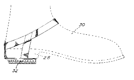
Figure 4 i~ a side elevational view of the
attachment when used ~ith the friction means only;
Figure 5 i~ a side elevational view of the
attachment when used ~,Tith the heel substitute; and
Figure 6 is a cross-sectional view taken along
15 lines 6-6 of figure 2..
n~r~TPTIO~ OF pp~lPR~I~Rn RMR~ IM~TTg
Referring to figure 1 of the drawings, there is
shown an anti-skid heel atta~ t, generally denoted 10,
which comprises three main components: a strap
20 arr~n~e t 12, an a~lti-skid metallic plate 14 and a
removable heel substitute 16.
The metallic plate 14 comprises a horizontal
plate portion 18 ada~?ted to lie under the heel of a
wearer's boot, shoe, or the like and a vertical plate
25 portion 20 adapted to bear against the rear portion of

~, 2159q27
the shoe or boot. The horizontal plate 18 has a rear
extension 22 which, together with a pair of ears 24 and
26 at the lower edge of the rear plate 20, engage a pin
27 to define a hinge arrangement so that the rear plate
5 20 may be pivoted from a raised position, such as shown
in figure 2, to a horizontal folded position, such as
shown in figure 3. The horizontal plate portion 18
includes a top face 19 which is adapted to bear against
the heel 28 of a boot or shoe 30 (see figures 4 and 5)
10 and an underface 21 which ~displays peripherally, on
opposite sides thereof, downwardly extending V-shaped
projections 32 defining friction means to the attal~ ~.
The strap arrangement 12 of the present
~ho.ll- consists o~ a pair of straps 34 and 36 to
15 secure the atta~ to the wearer ' 8 shoe or boot .
Strap 34 extends hori zontally under the underface 21
and through a pair of slots 38 and 40 (see figure 2) of
the horizontal plate portion 18. Opposite side portions
34 ' and 34" of the strap have their upper ends fixedly
20 attached, for example sewn, to opposite sides of the
second strap 36. The latter strap extends through a pair
of slots 42 and 44 ill the rear plate 20 and has its
opposite sides terminating with front free ends 36 ' and
36" in overlapped fashion. These ends are detAeh~hle 50
25 that the ankle area of a wearer may be positioned within
the opened strap arrangement. Various means are
envisaged in order to secure the strap ends 36 ' and 36"

O ` 21~9427
-- 7 --
together, such as a buckle, a Velcro-type material on one
or both faces, etc. The straps are made of pliable
tissue material so that, when use of the heel attachment
is not required and the owner wishes to store it in a
5 pocket or purse, the straps may be easily folded with the
rear plate 20 also folded in the horizontal position
shown in f igure 3 thereby def ining a compact unit that
may be stored.
An additional feature of the present invention
is that the heel att;~ ~ may be worn in certain areas
where the friction feature is not desired, t ~ Lly.
Therefore, the invention provides a heel substitute 16
which is formed of a rubber-like material and has a
contour adapted to fit against the underface 21 of the
15 horizontal plate 18. The top face of the heel substitute
has a rectangular ~ecessed area 50 in order to allow
passage of the horizontal portion 34a (see figure 6) of
the strap 34. The heel substitute 16 also includes one
or more magnets 52 (three being shown in figure 1) which
20 are fixedly inserted in the top face of the heel
substitute and which magnetically attach the heel
substitute to the metallic plate 18. As can be seen in
the figures of the drawing, the thickness of the heel
substitute is greater than the height of the projections
25 32 of the horizontal plate portion so as to nullify the
friction effect of the projections. Two front downward
projections 54 and 56 ~ombine with the side projections

-- 8 --
32 to confine the heel attachment under the horizontal
plate portion 18.
To facilitate the removal of the heel
substitute when the wt~arer wishes to use the anti-skid
5 feature of the att 1l 1 on an icy or slippery surface,
a front finger gripping projection 58 is integrally
formed to the material of the heel substitute. By
applying downward pressure on the extension 58,
disengagement of the ~agnets 52 to the plate 18 may be
10 easily accomplished.
Although the invention has been described above
in respect to one specific form, it will be evident to a
person skilled in the art that it may be modified and
15 refined in various ways. For example, instead of having
an arrangement of two straps 34 and 36, there may be
provided an arrangement of more straps, such as four,
each separately connected to the slots of the horizontal
and rear plates 18 ant~ 20. It i5 therefore wished to
20 have it understood that the present invention should not
be limited in scope, ex~ept by the terms of the following
claims .

Dessin représentatif
Une figure unique qui représente un dessin illustrant l'invention.
États administratifs

2024-08-01 : Dans le cadre de la transition vers les Brevets de nouvelle génération (BNG), la base de données sur les brevets canadiens (BDBC) contient désormais un Historique d'événement plus détaillé, qui reproduit le Journal des événements de notre nouvelle solution interne.

Veuillez noter que les événements débutant par « Inactive : » se réfèrent à des événements qui ne sont plus utilisés dans notre nouvelle solution interne.

Pour une meilleure compréhension de l'état de la demande ou brevet qui figure sur cette page, la rubrique Mise en garde , et les descriptions de Brevet , Historique d'événement , Taxes périodiques et Historique des paiements devraient être consultées.

Historique d'événement

Description Date
Demande non rétablie avant l'échéance 2003-09-29
Le délai pour l'annulation est expiré 2003-09-29
Réputée abandonnée - omission de répondre à un avis sur les taxes pour le maintien en état 2002-09-30
Inactive : Renseign. sur l'état - Complets dès date d'ent. journ. 2002-08-12
Inactive : Dem. traitée sur TS dès date d'ent. journal 2002-08-12
Lettre envoyée 2002-08-12
Exigences pour une requête d'examen - jugée conforme 2002-07-23
Toutes les exigences pour l'examen - jugée conforme 2002-07-23
Inactive : Page couverture publiée 2000-12-21
Demande publiée (accessible au public) 1997-03-29

Historique d'abandonnement

Date d'abandonnement Raison Date de rétablissement
2002-09-30

Taxes périodiques

Le dernier paiement a été reçu le 2001-09-14

Avis : Si le paiement en totalité n'a pas été reçu au plus tard à la date indiquée, une taxe supplémentaire peut être imposée, soit une des taxes suivantes :

  • taxe de rétablissement ;
  • taxe pour paiement en souffrance ; ou
  • taxe additionnelle pour le renversement d'une péremption réputée.

Les taxes sur les brevets sont ajustées au 1er janvier de chaque année. Les montants ci-dessus sont les montants actuels s'ils sont reçus au plus tard le 31 décembre de l'année en cours.
Veuillez vous référer à la page web des taxes sur les brevets de l'OPIC pour voir tous les montants actuels des taxes.

Historique des taxes

Type de taxes Anniversaire Échéance Date payée
TM (demande, 2e anniv.) - petite 02 1997-09-29 1997-09-23
TM (demande, 3e anniv.) - petite 03 1998-09-28 1998-09-14
TM (demande, 4e anniv.) - petite 04 1999-09-28 1999-09-15
TM (demande, 5e anniv.) - petite 05 2000-09-28 2000-09-14
TM (demande, 6e anniv.) - petite 06 2001-09-28 2001-09-14
Requête d'examen - petite 2002-07-23
Titulaires au dossier

Les titulaires actuels et antérieures au dossier sont affichés en ordre alphabétique.

Titulaires actuels au dossier
FRANCOIS CANDELA
Titulaires antérieures au dossier
S.O.
Les propriétaires antérieurs qui ne figurent pas dans la liste des « Propriétaires au dossier » apparaîtront dans d'autres documents au dossier.
Documents

Pour visionner les fichiers sélectionnés, entrer le code reCAPTCHA :


Pour visualiser une image, cliquer sur un lien dans la colonne description du document. Pour télécharger l'image (les images), cliquer l'une ou plusieurs cases à cocher dans la première colonne et ensuite cliquer sur le bouton "Télécharger sélection en format PDF (archive Zip)" ou le bouton "Télécharger sélection (en un fichier PDF fusionné)".

Liste des documents de brevet publiés et non publiés sur la BDBC .

Si vous avez des difficultés à accéder au contenu, veuillez communiquer avec le Centre de services à la clientèle au 1-866-997-1936, ou envoyer un courriel au Centre de service à la clientèle de l'OPIC.


Description du
Document 
Date
(aaaa-mm-jj) 
Nombre de pages   Taille de l'image (Ko) 
Dessin représentatif 1997-07-08 1 6
Dessin représentatif 2000-12-07 1 6
Abrégé 1995-09-27 1 18
Description 1995-09-27 8 242
Revendications 1995-09-27 5 125
Dessins 1995-09-27 2 68
Rappel - requête d'examen 2002-05-28 1 118
Accusé de réception de la requête d'examen 2002-08-11 1 193
Courtoisie - Lettre d'abandon (taxe de maintien en état) 2002-10-27 1 179
Taxes 1998-09-13 1 48
Taxes 2001-09-13 1 39
Taxes 1997-09-22 1 47
Taxes 1999-09-14 1 44
Taxes 2000-09-13 1 40