Sélection de la langue

Search

Sommaire du brevet 2159599 

Énoncé de désistement de responsabilité concernant l'information provenant de tiers

Une partie des informations de ce site Web a été fournie par des sources externes. Le gouvernement du Canada n'assume aucune responsabilité concernant la précision, l'actualité ou la fiabilité des informations fournies par les sources externes. Les utilisateurs qui désirent employer cette information devraient consulter directement la source des informations. Le contenu fourni par les sources externes n'est pas assujetti aux exigences sur les langues officielles, la protection des renseignements personnels et l'accessibilité.

Disponibilité de l'Abrégé et des Revendications

L'apparition de différences dans le texte et l'image des Revendications et de l'Abrégé dépend du moment auquel le document est publié. Les textes des Revendications et de l'Abrégé sont affichés :

  • lorsque la demande peut être examinée par le public;
  • lorsque le brevet est émis (délivrance).
(12) Demande de brevet: (11) CA 2159599
(54) Titre français: RACCORD DE TUYAUX
(54) Titre anglais: PIPE COUPLING
Statut: Réputée abandonnée et au-delà du délai pour le rétablissement - en attente de la réponse à l’avis de communication rejetée
Données bibliographiques
(51) Classification internationale des brevets (CIB):
  • F16L 23/032 (2006.01)
  • F16L 23/16 (2006.01)
  • F16L 23/18 (2006.01)
(72) Inventeurs :
  • BALL, DANIEL GRAHAM (Royaume-Uni)
(73) Titulaires :
  • DANIEL GRAHAM BALL
(71) Demandeurs :
(74) Agent: MCCARTHY TETRAULT LLP
(74) Co-agent:
(45) Délivré:
(22) Date de dépôt: 1994-04-05
(41) Mise à la disponibilité du public: 1994-10-13
Requête d'examen: 1999-06-29
Licence disponible: S.O.
Cédé au domaine public: S.O.
(25) Langue des documents déposés: Anglais

Traité de coopération en matière de brevets (PCT): Non

(30) Données de priorité de la demande:
Numéro de la demande Pays / territoire Date
9307083.7 (Royaume-Uni) 1993-04-03

Abrégés

Abrégé anglais


A pipe coupling for coupling together two lengths of pipe (4, 6) comprises first and second annular collars or flanges (8, 10) secured
to the ends of the lengths of pipe (4, 6) and having joining surfaces (12, 14) thereon which abut one another on securing of the lengths of
pipe (4, 6) together, radially aligned grooves (18, 20) being formed in the joining surfaces (12, 14) to constitute receiving means in which is
housed a seal (22) including a rigid first seal component (24) and a flexible second seal component (26) bonded to the first seal component
(24), the seal (22) extending partially into both grooves (18, 20) to seal between the joining surfaces (12, 14) of the collars (8, 10).

Revendications

Note : Les revendications sont présentées dans la langue officielle dans laquelle elles ont été soumises.


CLAIMS
1. A pipe coupling for coupling together first and
second lengths of pipe (4, 6), the coupling comprising a first
collar (8) secured to an end of the first length of pipe (4)
and having a joining surface (12) thereto, a second collar
(10) secured to an end of the second length of pipe (6) and
having a joining surface (14) thereto, the first and second
collars (8, 10) being positioned such that, when adjacent ends
of the first and second pipe lengths (4, 6) are brought into
contact with one another, the joining surfaces (12, 14) of the
first and second collars (8, 10) also contact one another, the
joining surfaces (12, 14) of the first and second collars (8,
10) each having formed therein radially-aligned grooves (18,
20) which, when the collars (8, 10) are brought into contact
with one another, define seal receiving means, a seal (22)
comprising a substantially rigid first seal component in the
form of a substantially rigid ring (24) the width of which is
slightly less than the combined width of the grooves (18, 20)
in the two collars (8, 10), and the outer diameter of which
is such that the ring (24) is a push-fit into the receiving
means, said seal (22) further comprising a resilient second
seal component (26), the seal (22) being positioned within the
seal receiving means to extend partially into both receiving
portions (18, 20) thereof and to seal between the joining
surfaces (12, 14) of the first and second collars (8, 10), and
means for securing together the first and second collars (8,

10), characterised in that the second seal component comprises
a resilient ring (26) of substantially inverted U-shape in
transverse section the width of which is slightly more than
the combined width of the grooves (18, 20) in the two collars
(8, 10), and the internal diameter of which is slightly larger
than the minimum diameter of each groove (18, 20).
2. A coupling as claimed in claim 1 in which the means
for securing the two collars (8, 10) together comprises a
clamp (16) embracing said collars (8, 10).
3. A coupling as claimed in claim 1 in which the means
for securing the two collars (8, 10) together comprise a
plurality of circumferentially-spaced bolts extending through
the collars (8, 10) axially thereof.

Description

Note : Les descriptions sont présentées dans la langue officielle dans laquelle elles ont été soumises.

~94/23~3 2 1 5 9 5 9 9 PCT/GB94/00719 -
PIPE COUPLING
TECHNICAL FIELD
This invention relates to a pipe coupling used to join
adjacent pipe lengths together to form a pipeline system.
BACKGROUND ART
A known pipe coupling comprises a clamp arrangement
incorporating a clamp which embraces adjacent ends of adjacent
pipe lengths. The clamp is tightened onto a seal so that the
coupling can withstand the maximum pressure the pipeline is
designed to carry.
The clamp arrangement may hold the pipe lengths together
by friction in low pressure situations, or may co-operate with
a y oo~e or shoulder formed at each end of each pipe length
in higher pressure situations.
Such clamp arrangements may be fixed into position by
bolting or over centre clamping.
A problem with known clamp arrangements is that it is
difficult to ensure accurate alignment of the internal bores
of adjacent pipe lengths, primarily due to the resilience of
the seal which can allow ad;acent pipe lengths to move
radially relative to one another, such as may occur as the
clamp is being tightened onto the pipe lengths.
A known method of overcoming this problem is to design
the pipe lengths to have one male end and one female end.
Joins between adjacent pipe lengths are then made between the
male end of one pipe length and the female end of another pipe

. .. .. -- --- - -
- . . . . --
:: ..-.:.- ------~ --- --- 21~9599
length. This allows adjacent pipe lengths to be located
accurately relative to one another and leads to alignment of
the bores of adjacent pipe lengths.
A disadvantage with this known system, however, is that
the pipe lengths can only be fitted into the pipeline in one
direction.
It has been proposed, in US 3~36159, to provide a sealing
ring reacting between the ends of adjacent pipe lengths and
comprising a resilient, deformable plastics component
sandwiched between inner and outer retainer rings of metal
such as steel which are resiliently deformable in a direction
radially of the pipe lenths.
In such an arrangement, the pressure in the pipeline
reacts prlmarily on the metal components of the seal.
DISCLOSURE OF THE L~v~iION
It wouid be desirable .o be able .o prcvide a pipe
coupling which ensured positive and accurate alignment of
adjacent pipe lengths, and therefore a smooth, cor nuous bore
therethrough, the ends of adjacent pi?e l_ ~ths being
identical, and which incorporated a seal the efficiency of
which inc_eased with increasing pressure within the pipeline.
According to the present invention there s provided a-
pipe coupling for coupling tcgether first and second lengths
of pipe, the coupling comprislng a first ccllar secured to an
end of the first length cf pi?e and havins a Joining surface
thereto, a second collar secured to an end of the second
~MENDED Sl;EET

~, 21$9599
length of pipe and having a joining surface thereto, the first
and second collars being positioned such that, when adjacent
ends of the first and second pipe lengths are brought into
contact with one another, the joining surfaces of the first
and second collars also contact one another, the joining
- surfaces of the first and second collars each having formed
therein radially-aligned grooves which, when the collars are
brought into contact with one another, define seal receiving
means, a seal comprising a substantially rigid first seal
component in the form of a substantially rigid ring the width
of which is slightly less than the combined width of the`
grooves in the two collars and the outer diameter of which is
such that the ring is a push-fit into the receiving means,
said seal further comprising a resilient second seal
component, the seal being positioned within the seal receiving
means to extend partially into both receiving portions
thereof and to seal between the joining surfaces of the first
and second collars, and means for securing together the i~irst
and second collars, characterised in that the second seal
component comprises a resilient ring of substantially inverted
U-shape in transverse section the width of which is slightly
more than the combined width of the grooves in the two
collars, and the internal diameter of which is slightly larger
than the m; n; ml)m diameter of each groove.
In use, the seal is positioned in the groove of a first
of the collars. Due to the size of the seal, a part of the
J~MENDED S~iEET

21`S9599
; ~ 4
seal extends beyond said receiving portion in the first
collar. This protruding part is used to locate the second
collar relative to the first collar by positioning the second
- collar such that the remaining part of the seal is located
within the groove in said second collar. Thus the arrangement
provides a convenient method of positively aligning two pipe
lengths to be joined to form a pipeline system.
The resilient ring is secured within the first, rigld
seal component and thus the rigid component forms the outer
periphery of the seal.
In use, the U-shaped resilient seal component reacts to
pressures from within the pipe lengths and increases its seal
efficiency as pressure increases.
A further advantage of the pipe coupling according to the
present invention is that adjacent pipe lengths can be rotated
relative to one another without the need for uncoupling.
BRIEF DESCRIPTION OF THE DRAWINGS
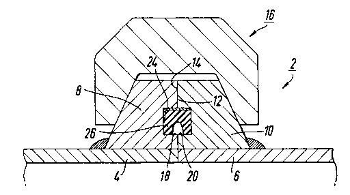
Figure 1 is a schematic longitudinal section through part
of a pipe coupling according to the present invention;
Figure 2 is a schematic transverse section through a
collar forming part of the pipe coupling in Figure 1;
Figures 3 and 4 are a side view and a front viëw
respectively of a clamp forming part of the pipe coupling of
Figure 1, and
Figure 5 is a front view, incorporating a transverse
section, of the seal forming part of the pipe coupling of
Figure 1.
AMENDED SHEET

2159599
094/~3 PCT/GB94/00719 `
DETAILED DESCRIPTION OF THE PREFERRED EMBODIMENT
Referring to the drawings, a pipe coupling according to
the present invention is designated generally by the reference
numeral 2. The pipe coupling comprises a first length of pipe
4 and a ~econA length of pipe 6 a wall of each of which is
shown in Fig. 1 and to the end of each of which are welded
associated annular collars 8, 10 respectively. The collars
have respective joining surfaces 12, 14 thereon arranged to
abut one another on coupling together of the pipe lengths
4, 6.
The rear face of each collar 8, 10 is of an outwardly and
forwardly tapering nature, the collars 8, 10 being held
together by a clamp indicated generally at 16 and provided
with a correspon~ngly tapered clamping surface therein.
The ~oining surfaces 12, 14 of the collars 8, 10 each
have formed therein a circular yloove or chAnnel 18, 20
respectively, the two g ooves 18, 20 being accurately radially
aligned with one another to form seal receiving means into
which can be positioned a seal indicated generally at 22.
More particularly, the seal 22 comprises an outer metal
ring 24 of substantially rigid, collo~ive-resistant material
and of generally L-shaped in transverse section to which is
hon~ an inner ring 26 of a flexible material such as
plastics or rubber and of generally inverted U-shape in
transverse section, the flexible ring 26 and the metal ring
24 forming a unitary seal.

W094/23233 ~ ~$9S 9 9 PCT/GB94100719
The width of the metal ring 24, considered in the axial
direction of the coupling, is slightly less than the combined
depth of the two grooves 18, 20 constituting the seal
receiving means, typically 0.13mm less, while the diameter of
the metal ring 24 is such that it is a push-fit into one or
other of the y~ooves 18, 20 to project partially therefrom.
The width of the flexible ring 26, again considered in
the axial direction of the coupling, is slightly more than the
combined depths of the two y-ooves 18, 20, while the internal
diameter of said ring 26 is slightly larger than the common
minimum diameter of the y~ooves 18, 20.
In order to achieve a sealed coupling between the two
pipe lengths 4, 6, the seal 22 is pushed into the ~,oove 18
in the collar 8 so that it seats in said ~-oove and projects
partially therefrom.
The other collar 10 is then pushed onto the protruding
part of the seal 22. The rigid nature of the portion 24 of
the seal, and the accurate radial alignment of the two grooves
18, 20 ensure that the two pipe lengths 4, 6 are then
accurately aligned with one another with the internal bores
thereof forming accurate continuations of one another.
The portions of the clamp 16 are then positioned over the
abutting collars 8, 10 and are tightened up to secure the two
pipe lengths 4, 6 together. The clamp 16 may be of the bolted
or quick-connect type.
In an alternative embodiment of the invention, the

~94/23233 21 S 9 ~ 9 g PCT/GB94/00719
collars 8, lO comprise parallel-sided annular flanges secured
to respective ends of the pipe lengths 4, 6, said flanges
being secured together by a plurality of circumferentially-
spaced bolts extending through the flanges parallel with the
central axis of the pipeline and radially outwardly of the
seal 22.
In all cases, the inverted U-shaped component 26 of the
seal 22 reacts to the pressure of fluid within the pipeline,
said pressure being exerted on the concave surface of the ring
26 to urge the outer walls of the ring 26 against the base
walls of the two ylooves 18, 20 to seal between the two
surfaces 12, 14. Thus it will be appreciated that in fact the
efficiency of this seal increases with increase of pressure
within the pipeline.
A coupling according to the invention is suitable for
pipelines being used to transport, for example, liquids or
slurries at high pressure of typically up to 350 bars or
higher. However, it can be used at lower pressures, for
example lO bars.
Two pipe lengths coupled by means of the clamp 16 may be
rotated relative to one another without having to decouple the
pipe lengths, it merely being necessary to loosen the clamping
effect of the clamp 16.

Dessin représentatif
Une figure unique qui représente un dessin illustrant l'invention.
États administratifs

2024-08-01 : Dans le cadre de la transition vers les Brevets de nouvelle génération (BNG), la base de données sur les brevets canadiens (BDBC) contient désormais un Historique d'événement plus détaillé, qui reproduit le Journal des événements de notre nouvelle solution interne.

Veuillez noter que les événements débutant par « Inactive : » se réfèrent à des événements qui ne sont plus utilisés dans notre nouvelle solution interne.

Pour une meilleure compréhension de l'état de la demande ou brevet qui figure sur cette page, la rubrique Mise en garde , et les descriptions de Brevet , Historique d'événement , Taxes périodiques et Historique des paiements devraient être consultées.

Historique d'événement

Description Date
Inactive : CIB de MCD 2006-03-12
Demande non rétablie avant l'échéance 2001-04-05
Le délai pour l'annulation est expiré 2001-04-05
Réputée abandonnée - omission de répondre à un avis sur les taxes pour le maintien en état 2000-04-05
Modification reçue - modification volontaire 1999-08-24
Inactive : Renseign. sur l'état - Complets dès date d'ent. journ. 1999-07-21
Inactive : Dem. traitée sur TS dès date d'ent. journal 1999-07-21
Lettre envoyée 1999-07-21
Exigences pour une requête d'examen - jugée conforme 1999-06-29
Toutes les exigences pour l'examen - jugée conforme 1999-06-29
Lettre envoyée 1998-04-06
Exigences de rétablissement - réputé conforme pour tous les motifs d'abandon 1998-03-20
Réputée abandonnée - omission de répondre à un avis sur les taxes pour le maintien en état 1997-04-07
Demande publiée (accessible au public) 1994-10-13

Historique d'abandonnement

Date d'abandonnement Raison Date de rétablissement
2000-04-05
1997-04-07

Taxes périodiques

Le dernier paiement a été reçu le 1999-04-06

Avis : Si le paiement en totalité n'a pas été reçu au plus tard à la date indiquée, une taxe supplémentaire peut être imposée, soit une des taxes suivantes :

  • taxe de rétablissement ;
  • taxe pour paiement en souffrance ; ou
  • taxe additionnelle pour le renversement d'une péremption réputée.

Les taxes sur les brevets sont ajustées au 1er janvier de chaque année. Les montants ci-dessus sont les montants actuels s'ils sont reçus au plus tard le 31 décembre de l'année en cours.
Veuillez vous référer à la page web des taxes sur les brevets de l'OPIC pour voir tous les montants actuels des taxes.

Historique des taxes

Type de taxes Anniversaire Échéance Date payée
TM (demande, 4e anniv.) - petite 04 1998-04-06 1998-03-20
Rétablissement 1998-03-20
TM (demande, 3e anniv.) - petite 03 1997-04-07 1998-03-20
TM (demande, 5e anniv.) - petite 05 1999-04-06 1999-04-06
Requête d'examen - petite 1999-06-29
Titulaires au dossier

Les titulaires actuels et antérieures au dossier sont affichés en ordre alphabétique.

Titulaires actuels au dossier
DANIEL GRAHAM BALL
Titulaires antérieures au dossier
S.O.
Les propriétaires antérieurs qui ne figurent pas dans la liste des « Propriétaires au dossier » apparaîtront dans d'autres documents au dossier.
Documents

Pour visionner les fichiers sélectionnés, entrer le code reCAPTCHA :


Pour visualiser une image, cliquer sur un lien dans la colonne description du document. Pour télécharger l'image (les images), cliquer l'une ou plusieurs cases à cocher dans la première colonne et ensuite cliquer sur le bouton "Télécharger sélection en format PDF (archive Zip)" ou le bouton "Télécharger sélection (en un fichier PDF fusionné)".

Liste des documents de brevet publiés et non publiés sur la BDBC .

Si vous avez des difficultés à accéder au contenu, veuillez communiquer avec le Centre de services à la clientèle au 1-866-997-1936, ou envoyer un courriel au Centre de service à la clientèle de l'OPIC.


Description du
Document 
Date
(aaaa-mm-jj) 
Nombre de pages   Taille de l'image (Ko) 
Abrégé 1994-10-12 1 49
Description 1994-10-12 7 258
Dessins 1994-10-12 2 38
Revendications 1994-10-12 2 60
Description 1999-08-10 7 277
Revendications 1999-08-10 2 62
Dessins 1999-08-10 2 42
Dessin représentatif 1998-07-19 1 12
Avis de retablissement 1998-04-05 1 172
Accusé de réception de la requête d'examen 1999-07-20 1 193
Courtoisie - Lettre d'abandon (taxe de maintien en état) 2000-05-02 1 183
PCT 1995-09-28 15 595
Taxes 1999-04-05 1 34
Taxes 1998-03-19 1 47
Taxes 1997-05-06 2 121