Note : Les descriptions sont présentées dans la langue officielle dans laquelle elles ont été soumises.
21~9852
1 u~lv~SAL SOCKET TOOL
2 Background and Summary of the Invention:
The instant invention relates to socket tools and
6 more particularly to a universal socket tool which is
7 operative for turning a plurality of different size
8 fastening elements, such as nuts, bolts, slotted screws,
9 phillips head screws, eye bolts, wing nuts, etc.
Universal socket tools have heretofore been known in
11 the art. In this connection, the Applicant's earlier
12 issued U.S. Patent No. 4,887,498 represents the closest
13 prior art to the subject invention of which the Applicant
14 is aware. The '498 patent discloses a universal soc~et
tool comprising a housing forming a chamber having an
16 open lower end, and a bundle of over four hundred
17 individual pins suspended longitudinally within the
18 chamber by a plurality of side-by-side rails. The lower
19 ends of the pins are adapted for engaging various
fastening elements when the lower ends of the pins are
21 pressed downwardly over the fastening element. The pins
22 are suspended such that when the lower end of the pins
23 engages with a fastening element, the engaged pins are
24 forced to slide upwardly into the chamber. A highly
complex spring assembly is provided for returning the
26 pins to their original position after pressured
2159852
1 engagement with the fastening element is removed. While
2 the socket tool described in the '498 patent is highly
3 effective in operation, the large number of small pins
4 and complicated spring assembly make the device extremely
difficult to assemble and expensive to manufacture.
6 Accordingly, the prior art device has not found
7 widespread acceptance among users.
8 The instant invention provides three improved
9 embodiments of a universal socket tool which are simple
in design, easy to assemble and inexpensive to
11 manufacture. A first embodiment of the universal socket
12 tool comprises a rectangular housing having a
13 longitudinal chamber with an open lower end. The
14 rectangular configuration of the housing prevents rolling
of the socket tool when it is placed on a flat resting
16 surface. An eight-by-eight array of one-eighth inch
17 square pins are longitudinally oriented in the chamber
18 wherein the lower ends of the pins are flush with the
19 open end of the chamber and are adapted for engagement
with a plurality of different size and shape fastening
21 elements. A selected group of side-by-side pins have
22 tapered end portions which are operative for engagement
23 with a slotted or phillips head screw. The larger size,
24 one-eighth inch square pins significantly reduce the
number of pins required in the array while still
26 retaining the same effectiveness in engaging and turning
- 2159852
1 different size fastening elements. The pins are
2 suspended in the chamber in individual sliding relation
3 wherein engagement of the lower ends of the pins with a
4 fastening element forces the engaged pins upwardly into
the chamber. The suspension system includes upper and
6 lower suspension plates which are mounted in closely
7 spaced parallel relation in the chamber. The upper and
8 lower suspension plates have aligned apertures for
9 slidably receiving the pins. A flange at the top of each
pin is positioned above the upper plate and the lower end
11 of each pin is located below the lower plate. Each of
12 the pins is further provided with a coil spring disposed
13 around its upper end for returning the pins to their
14 normal position after pressured engagement with a
fastening element is terminated. The upper and lower
16 suspension plates are preferably divided into four
17 separate plate segments so that the pins can be assembled
18 in sub-groups. In a second embodiment of the universal
19 socket tool, the suspension system comprises a plurality
of side-by-side retainer elements each having a plurality
21 of downwardly extending mounting heads, and further
22 comprises a plurality of springs each having a first end
23 secured to the upper end of a corresponding pin and a
24 second end received over a mounting head on a
corresponding retainer element. The springs may be
26 secured to the tops of the pins by an adhesive, or
2l59852
1 -alternatively the tops of the pins may include mounting
2 heads for receiving the end of the spring. In a third
3 embodiment of the universal socket tool, the suspension
4 system comprises an adhesive medium received in the
chamber, and further comprises a plurality of coil
6 springs each having a first end respectively secured to
7 the upper end of a corresponding pin and a second end
8 imbedded in the adhesive medium. The springs may be
9 secured to the tops of the pins by an adhesive, or
alternatively the tops of the pins may include mounting
11 heads for receiving the end of the spring.
12 Accordingly, it is an object of the instant
13 invention to provide a universal socket tool which is
14 operative for engaging and turning a plurality of
different size fastening elements.
16 It is another object to provide a universal socket
17 tool which is inexpensive to manufacture.
18 It is yet another object to provide a universal
19 socket tool having a housing with at least one flat side
to prevent rolling when placed on a flat surface.
21 It is still another object to provide a universal
22 socket tool wherein selected side-by-side pins have
23 tapered end portions which are operative for engagement
24 with a slotted or phillips-type screw head.
2159852
1 It is a further object to provide a universal socket
2 tool having a simple suspension system which is easy to
3 assemble.
4 other objects, features and advantages of the
invention shall become apparent as the description
6 thereof proceeds when considered in connection with the
7 accompanying illustrative drawings.
- 2159852
1 Description of the Drawings:
2 In the drawings which illustrate the best mode
3 presently contemplated for carrying out the present
4 invention:
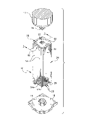
Fig. 1 is a perspective view of a first embodiment
6 of the instant universal socket tool shown in connection
7 with a drive wrench and fastening element;
8 Fig. 2 is another perspective view thereof;
9 Fig. 3 is a cross-sectional view thereof taken along
line 3-3 of Fig. 1;
11 Fig. 4 is an exploded perspective view of a first
12 embodiment of a pin sub-assembly therefor;
13 Fig. 5 is an exploded perspective view of second
14 embodiment of a pin sub-assembly therefor;
Fig. 6 is another perspective view, partially broken
16 away and partially exploded, of the universal socket
17 tool;
18 Fig. 7 is an enlarged cross-sectional view showing
19 the manner in which the pins are displaced to accommodate
a hex head bolt;
21 Fig. 8 is an another enlarged cross-sectional view
22 showing the manner in which the pins are displaced to
23 accommodate a hex nut and bolt:
24 Fig. 9 is yet another enlarged cross~sectional view
showing the manner in which the pins are displaced and
26 received into the head of a slotted screw;
21$98~2
1 Fig. 10 is a cross-sectional view showing an
2 alternative embodiment of the tapered end portions of the
3 pins;
4 Fig. 11 is a perspective view of a second embodiment
of the universal socket tool;
6 Fig. 12 is a cross-sectional view thereof taken
7 along line 12-12 of Fig. 11;
8 Fig. 13 is an exploded assembly view of the
9 suspension assembly thereof;
Fig. 14 is a perspective view of a third embodiment
11 of the universal socket tool; and
12 Fig. 15 is a cross-sectional view thereof taken
13 along line 15-15 of Fig. 14.
2159852
1 Description of the Preferred Embodiment:
2 Referring now to the drawings, the universal socket
3 tool of the instant invention is illustrated and
4 generally indicated at 10 in Figs. 1-10. As will
hereinafter be more fully described, the instant
6 universal socket tool 10 is operative in connection with
7 a drive tool 12 (partially illustrated) for turning a
8 plurality of different fastening elements 14, such as
9 nuts, bolt, screws, eye bolts and wing nuts. The drive
tool 12 comprises a conventional socket driver having a
11 square mounting lug 16. The fastening element 14 in
12 Figs. 1 and 7 comprises a hex head bolt which is
13 threadedly mounted in the flat plate 18.
14 The universal socket tool 10 comprises a housing
generally indicated at 20 including a longitudinal
16 chamber generally indicated at 22 having an upper end 24
17 and an open lower end 26. The universal socket tool
18 further comprises a plurality of individual pins
19 generally indicated at 28 which are slidably suspended
within the chamber 22. The housing 20 is preferably
21 tubular in configuration, and in this connection, the
22 housing preferably comprises a section of one and one-
23 quarter (1/4) inch square tubular stainless steel. The
24 stainless steel tubular housing has a one eighth inch
thick outer wall which defines an internal longitudinal
26 chamber 22 having a one inch by one inch dimension. The
- 2159852
1 square outside configuration of the housing 20 provides
2 an advantage over the cylindrical prior art devices in
3 that it prevents rolling of the socket tool 10 when it is
4 placed on a flat resting surface. The square design also
allows a leveraging tool, such as an open-ended wrench,
6 to grasp the housing 20 to aid in turning. While the
7 housing 20 is shown to have a square configuration, it is
8 to be understood that the housing 20 need only have one
9 flat side to prevent rolling. For example, the
housing 20 may be generally cylindrical with one flat
11 surface, or it may be octagonal in configuration with
12 eight flat surfaces. The housing 20 still further
13 includes a small opening 30 adjacent the upper end
14 thereof for receiving a cleaning fluid therein when
desired.
16 Each of the individual pins 28 comprises a lower end
17 consisting of a one-eighth inch square rod 32 and an
18 upper end consisting of a cylindrical stem 34 having a
19 flange 36 at the top thereof. The cylindrical stem 34 of
the pin 28 is fixedly received into an axial bore 38
21 (Figs. 4 and 5) formed in one end of the square rod
22 portion 32. The pins 28 are arranged in an eight-by-
23 eight array and are longitudinally oriented and slidably
24 suspended in a first normal position (Fig. 3) within the
25 chamber 22 so that the square rod portions 32 of the pins
26 28 are adjacent the open end 26 of the chamber 22. The
- 2159852
1 pins 28 may be mounted so that they are flush with the
2 end of the chamber 26 as illustrated in the drawings, or
3 alternatively, the pins 28 may extend below the end of
4 the housing 20 in order to engage below surface screws or
bolts, such as those positioned in recessed cavities.
6 The eight-by-eight array of one-eighth inch pins
7 completely fills the one inch square chamber 22 of the
8 tubular housing 20 so that the pins 28 are only permitted
9 to move in vertical sliding relation. It is pointed out
that the four corner pins 28A have lower ends consisting
11 of round rods 32A to accommodate for the rounded internal
12 corners of the tubular housing 20. The plurality of pins
13 28 further include a selected grouping of side-by-side
14 pins 28B which have tapered end portions 40. The side-
by-side tapered end portions 40 are operative for
16 engagement with a slotted or phillips head screw 14B (See
17 Fig. 9). It is contemplated that the tapered portions 40
18 of the pins 28 could be positioned on one side of the
19 pin 28, such as illustrated in Fig. 10, whereby the
tapered portions of the side-by-side pins would cooperate
21 to form a blade. In this manner, the tapered blade would
22 be positioned centrally with respect to the housing 20
23 and would facilitate rotation.
24 The pins 28 are suspended within the chamber 22 in
individual sliding relation, wherein engagement of the
26 s~uare rods 32 of the pins 28 with a fastening element 14
- 2159852
1 forces the engaged pins 28 upwardly into the chamber 22
2 to a second position (See Figs. 7-9). More specifically,
3 the pins 28 are suspended within the chamber 22 by means
4 of upper and lower suspension plates generally indicated
at 42 and 44 respectively, mounted in closely spaced
6 parallel spaced relation adjacent the upper end 24 of the
7 chamber 22. The upper and lower suspension plates 42 and
8 44 are generally square in configuration although they
9 have rounded corners to accommodate for the rounded
internal corners of the housing 20. The two suspension
11 plates 42 and 44 each include an eight-by-eight array of
12 apertures 46 for slidably receiving the cylindrical stem
13 portions 34 of the pins 28. The apertures 46 in the
14 suspension plates 42 and 44 are aligned in overlying
relation so as to form vertical guides for the pins 28
16 when they are assembled therein. Each of the pins 28 is
17 assembled with_the suspension plates 42 and 44 such that
18 the flange 36 at the upper end of the pin 28 is
19 positioned above the upper suspension plate 42 and the
square rod portion 32 of the pin 28 is positioned below
21 the lower suspension plate 44.
22 Each of the pins 28 further includes a compression
23 spring 48 for returning the pins 28 from the second
24 position to the first normal position after pressured
- engagement with the fastening element 14 is eliminated.
26 The compression spring 48 is received around the stem
- 2159852
1 portion 34 of each pin 28 and is captured between the
2 lower suspension plate 44 and the shoulder 50 formed
3 between the stem portion 34 and rod portion 32 of the pin
4 28. Assembly of the pins 28 is accomplished by extending
the upper cylindrical stem portion 34 of the pin 28
6 through the aligned plate apertures 46, through the
7 compression spring 48 and securing the stem portion 34
8 into the bore 38 in the rod portion 32 of the pin 28.
9 The suspension plates 42 and 44 and assembled pins
28 are mounted within the chamber 22 by two mounting rods
11 52 (Fig. 6) which extend laterally through the chamber 22
12 between the two spaced suspension plates 42 and 44. The
13 ends of the rods 52 are secured by any suitable means
14 within holes S4 in the outer wall of the housing 20.
Referring to Fig. 4, the upper and lower suspension
16 plates 42 and 44 are preferably formed in four individual
17 segments 42' and 44' each having a 2-by-8 array of
18 apertures 46 therein. The segmented arrangement of the
19 suspension plates 42 and 44 simplifies the assembly
procedure by providing more working space in which the
21 upper and lower pin portions 32 and 34 and the springs 48
22 can be manually manipulated. Referring to Fig. 5, an
23 alternative arrangement of the plate segments 42' and 44'
24 is illustrated. Each of the apertures 46 in the
alternative plate segments 42' and 44' is provided with
26 a slot 56 which extends outwardly to the peripheral edge
21S985~
1 of the plate. In this connection, the upper and lower
2 ends 32 and 34 of the pin 28, and the spring 48 can be
3 assembled independently of the suspension plates 42' and
4 44' and then the cylindrical stem 34 of the assembled
pins 28 can be snap received into the apertures 46 from
6 the side slots 56 of the plates 42' and 44'. The
7 simplification of assembly accomplished by this
8 alternative arrangement can readily be appreciated. It
9 is pointed out that the mounting rods 52 must extend
through the housing 20 perpendicular to the plate
11 segments 42' and 44' in order to secure each of the
12 plates within the housing 20 (See Fig. 6).
13 The universal socket tool 10 still further comprises
14 a drive receptacle 58 for receiving the lug 16 of the
socket driver 12. The drive receptacle 58 comprises a
16 square body 60 having a square opening 62 centrally
17 located therein. The drive receptacle 58 preferably
18 comprises an integral body unit although it is
19 contemplated that it could comprise a set of annular
stacked plates. The body 60 of the drive receptacle 58
21 is slidably received into the upper end of the housing 20
22 wherein it is secured in position by two pins 64 which
23 extend through apertures 66 in the outer wall of the
24 housing 20 and into bores 68 in the receptacle body 60.
The square opening 62 in the receptacle body is operative
26 for snap receiving the lug 16 of the socket driver 12 so
- ~ 2ls98s2
1 that the universal socket tool 10 can be used in a
2 conventional manner.
3 In use, the pins 28 are pressed downwardly over the
4 top of a fastening element 14, such as a hex head bolt
(See Figs. 1 and 7). In this connection, engagement of
6 the rod portions 32 of the pins with the fastening
-7 element 14 forces the engaged pins 28 upwardly into the
8 chamber 22 to a second position. The remaining unengaged
9 pins 28 are operative for grasping the sides of the
fastening element 14 and rotating the fastening element
11 14 when the socket tool 10 is rotated. Rotation of the
12 socket tool 10 is accomplished by means of the socket
13 driver 12 in a conventional manner. The pins 28 are
14 returned to their normal resting position (Fig. 3) by the
compression springs 48 when pressured engagement of the
16 socket tool 10 over the fastening element 14 is
17 eliminated.
18 Referring to Figs. 8 and 9, displacement of the
19 pins 28 in connection with a threaded nut 14A and a
slotted screw head 14B is illustrated. In Fig. 9, it can
21 be seen that the pins 28B having tapered end portions 40
22 are operative for engagement in the slotted head of the
23 screw 14B for rotation thereof. It is again pointed out
24 that the tapered ends 40 of the pins 28B are equally
effective for engagement with the head of a phillips head
26 screw (not shown).
1 5
1 While the size of the housing 20 has been
2 specifically defined as comprising a one and one-quarter
3 (1/4) inch square tubular housing, it is to be understood
4 that smaller and larger size socket tools are also
contemplated within the scope of the invention. However,
6 it is pointed out that the size of the rod portions 32
7 (one-eighth inch square) of the pins 28 would remain the
8 same for all embodiments up to two inches in size. For
9 example, a one inch socket tool having an internal
chamber dimension measuring three-quarter (3/4) inch
11 square would require a six-by-six array of one-eighth
12 inch square pins. However, when the size of the socket
13 tool exceeds two inches square, the size of the pins must
14 increase to one-quarter (1/4) inch. For example, a two
and one-quarter (2 1/4) inch socket tool having an
16 internal chamber dimension measuring two inches square
17 would require an eight-by-eight array of one-quarter inch
18 pins. It is pointed out that the one-eighth inch (1/8)
19 and one-quarter inch (1/4) sizes of the pins have
particular significance in that it provides snug
21 engagement for virtually all standard and metric size
22 nuts. It has been found that the one-eighth and one-
23 quarter inch size pins have a direct arithmetical
24 proportion to virtually all sizes of nuts and bolts. A
deviation of more than ten percent from the one-eighth
26 and one-quarter inch sizes causes significant problems in
- 21598s2
16
1 allowing engagement with all sizes of nuts and bolts. It
2 is further contemplated that the lower ends 32 could
3 comprise allen-type pins wherein the universal socket
4 tool would be operative for universally engaging all size
allen head screws and bolts.
6 Referring now to Figs. 11-13, a second embodiment of
7 the universal socket tool is illustrated and generally
8 indicated at 70. Socket tool 70 comprises a one inch
9 square housing 72 having an internal chamber 74, and
further comprises a six-by-six array of one-eight inch
11 square pins 76 suspended in the chamber 74. Each of the
12 pins 76 preferably includes a rounded mounting head 78
13 which is supported by a neck 80. The corner pins 76A are
14 preferably rounded to accommodate the rounded inner
corners of the housing 72. Selected side-by-side pins 76B
16 include tapered ends portions 82 for engagement with
17 slotted screw heads. The pins 76 are suspended by means
18 of a plurality of retainer elements generally indicated
19 at 84 mounted in side-by-side relation adjacent the upper
end of the chamber 74, and a plurality of springs 86. The
21 retainer elements 84 are preferably fashioned from a
22 synthetic resin material, and each preferably includes a
23 plurality of downwardly extending mounting heads 88
24 supported by a neck 90. Each spring 86 has a first end 92
which is respectively received over mounting head 78 of
26 a corresponding pin 76 and a second end 94 which is
- 21598S2
1 received over mounting head 88 on retainer element 84.
2 Retainer elements 84 are mounted within chamber 74 by
3 means of three mounting rods 96 which pass through
4 aligned bores 98 (Fig. 13). Mounting rods 96 are secured
within holes in the housing 72 as described previously.
6 A spacer 100 and a drive receptacle 102 are mounted at
7 the upper end of the housing 72. Drive receptacle 102 is
8 mounted to housing 72 by means of pins 104 as previously
9 described. In use, the tool 70 functions as previously
described.
11 Referring now to Figs. 14 and 15, a third embodiment
12 of the universal socket tool is illustrated and generally
13 indicated at 106. Socket tool 106 comprises a one inch
14 square housing 108 having an internal chamber 110, and
further comprises a six-by-six array of one eight inch
16 square pins 112 suspended in the chamber 110. The corner
17 pins 112A are preferably rounded to accommodate the
18 rounded inner corners of the housing 108. Each of the
19 pins 112 preferably includes a rounded mounting head 114
which is supported by a neck 116. Selected side-by-side
21 pins 112B include tapered ends portions 118 for
22 engagement with slotted screw heads. The pins 112 are
23 suspended in the chamber by means of an adhesive medium
24 120 (Fig. 15), and a plurality of springs 122. Each
spring 122 has a first end 124 which is respectively
26 received over mounting head 14 of a corresponding pin
21s9852
18
1 112, and a second end 126 which is imbedded in the
2 adhesive medium 120. In the alternative, spring 122 may
3 be secured to pin 112 by welding, gluing, steaking, or
4 any other suitable method. The adhesive medium 120
preferably comprises a synthetic resin, such as an epoxy
6 glue. The resin is preferably poured into the chamber 110
7 in a liquid form wherein it is captured within the
8 housing 108 by a solid plate 128 supported within the
9 chamber 110 by drive receptacle 130. A preassembled array
of pins 112 is then lowered into the chamber 110 wherein
11 the ends 126 of the springs 122 are imbedded in the
12 adhesive medium 120. When the adhesive 120 hardens, the
13 spring ends 126 and the plate 128 are permanently secured
14 within the housing 108. The drive receptacle 130 is
mounted to the housing by means of pins 132 as previously
16 described. In use, the tool 106 functions as previously
17 described.
18 It can therefore be seen that the instant invention
19 provides three separate unique and novel embodiments of
a universal socket tool. The simplified designs of the
21 socket tools lend themselves to simple and inexpensive
22 manufacturing techniques. The enlarged one eighth inch
23 size of the pins provides for snug engagement of
24 virtually all standard and metric size nuts while
significantly reducing the number of pins required in the
26 array. The square shape of the housing provides a unique
- 215~852
1 feature in that it prevents the socket tool from rolling
2 when it is placed on a flat resting surface. While the
3 enlarged size pins would not normally be effective for
4 engagement with slotted or phillips head screws, a
selected grouping of side-by-side pins in each of the
6 embodiments is provided with tapered end portions for
7 overcoming this problem. The suspension systems of the
8 instant socket tools are greatly simplified thereby
9 allowing simplified assembly while retaining the same
effectiveness. For these reasons, the instant invention
11 is believed to represent a significant advancement in the
12 art which has substantial commercial merit.
13 While there is shown and described herein certain
14 specific structure embodying the invention, it will be
manifest to those skilled in the art that various
16 modifications and rearrangements of the parts may be made
17 without departing from the spirit and scope of the
18 underlying inventive concept and that the same is not
19 limited to the particular forms herein shown and
described except insofar as indicated by the scope of the
21 appended claims.