Sélection de la langue

Search

Sommaire du brevet 2160042 

Énoncé de désistement de responsabilité concernant l'information provenant de tiers

Une partie des informations de ce site Web a été fournie par des sources externes. Le gouvernement du Canada n'assume aucune responsabilité concernant la précision, l'actualité ou la fiabilité des informations fournies par les sources externes. Les utilisateurs qui désirent employer cette information devraient consulter directement la source des informations. Le contenu fourni par les sources externes n'est pas assujetti aux exigences sur les langues officielles, la protection des renseignements personnels et l'accessibilité.

Disponibilité de l'Abrégé et des Revendications

L'apparition de différences dans le texte et l'image des Revendications et de l'Abrégé dépend du moment auquel le document est publié. Les textes des Revendications et de l'Abrégé sont affichés :

  • lorsque la demande peut être examinée par le public;
  • lorsque le brevet est émis (délivrance).
(12) Brevet: (11) CA 2160042
(54) Titre français: TREPAN A ELEMENT D'ENTRAINEMENT ET ELEMENT DE COUPE
(54) Titre anglais: DRILLING TOOL BIT WITH A CARRIER MEMBER AND CUTTER MEMBER
Statut: Périmé et au-delà du délai pour l’annulation
Données bibliographiques
(51) Classification internationale des brevets (CIB):
  • B28D 01/14 (2006.01)
  • B28D 01/04 (2006.01)
  • B28D 01/26 (2006.01)
  • E21B 10/48 (2006.01)
(72) Inventeurs :
  • KLEINE, WERNER (Allemagne)
(73) Titulaires :
  • HILTI AKTIENGESELLSCHAFT
(71) Demandeurs :
  • HILTI AKTIENGESELLSCHAFT (Liechtenstein)
(74) Agent: EUGENE J. A. GIERCZAKGIERCZAK, EUGENE J. A.
(74) Co-agent:
(45) Délivré: 1999-01-12
(22) Date de dépôt: 1995-10-06
(41) Mise à la disponibilité du public: 1996-04-16
Requête d'examen: 1996-02-12
Licence disponible: S.O.
Cédé au domaine public: S.O.
(25) Langue des documents déposés: Anglais

Traité de coopération en matière de brevets (PCT): Non

(30) Données de priorité de la demande:
Numéro de la demande Pays / territoire Date
P 44 36 916.6 (Allemagne) 1994-10-15

Abrégés

Abrégé français

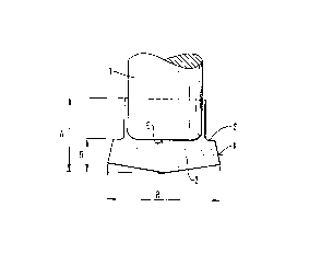
La présente invention a pour objet un outil de forage comportant un porte-outil ayant la forme, par exemple, d'une couronne annulaire. Dans cette couronne, plusieurs outils de forage sont régulièrement espacés à l'extrémité de travail du porte-outil. Les bords d'attaque des outils de forage sont en prolongement radial vers l'extérieur et vers l'intérieur de l'épaisseur de la paroi du porte-outil. Un gradin (S) est formé dans les outils de forage à une certaine distance du bord d'attaque dans la direction du forage. Le gradin (S) est situé à l'extrémité arrière d'une région (K) correspondant à une zone de réduction continue de la dimension radiale (R) de l'outil de forage, la dimension radiale atteignant son minimum au niveau du gradin. Du fait de la réduction de la dimension radiale au niveau du gradin (S), la longueur de l'outil de forage dans la direction du forage, source de friction entre celui-ci et les parois du trou à forer, se trouve réduite après une certaine période d'utilisation de l'outil de forage, ce qui permet à l'outil de forage de conserver plus longtemps son efficacité de coupe.


Abrégé anglais


A drilling bit includes a carrier member shaped, for
instance, as a hollow annular crown. In such a crown
several cutter members are distributed angularly apart
around the circumferentially extending leading end of the
carrier member. The cutter members project both radially
outwardly and inwardly from the wall thickness of the
carrier member. A step (S) is formed in the cutter
members spaced from the leading end thereof in the
drilling direction. The step(S) is located at the
trailing end of a region (K) with a continuous reduction
in the radial dimension (R) of the cutter member and the
radial dimension is further reduced at the step. Due to
the further reduction in the radial dimension at the step
(S), the length of the cutter member in the drilling
direction, causing friction with the wall surface of the
borehole to be drilled, is limited after extended use of
the drilling bit, so that the drilling bit retains a
higher drilling efficiency even after such extended use.

Revendications

Note : Les revendications sont présentées dans la langue officielle dans laquelle elles ont été soumises.


The embodiments of the invention in which an exclusive
property or privilege is claimed are defined as follows:
1. A drilling bit having a drilling direction and
comprising an axially extending carrier member having a
leading end facing in the drilling direction and at least
one cutter member located at the leading end of said
carrier member and having a leading end with a dimension
(R) extending transversely of the drilling direction of
said carrier member and an axially extending region (K)
extending from the leading end with a continuously
diminishing transverse dimension in the direction
opposite to the drilling direction to a trailing end
thereof, said at least one carrier member projects in the
drilling direction and in the radial direction from the
leading end of said carrier member, and said at least one
cutter member has a radially inwardly directed step (S)
at the trailing end of said region (K).
2. A drilling bit, as set forth in claim 1,
wherein said at least one cutter member has an axial
dimension extending from the leading end thereof to the
step (S) corresponding approximately to 0.3 to 0.5 times
the full axial length (A) of said at least one cutter
member .

3. A drilling bit, as set forth in claim 1 or 2,
wherein the step (S) is located in the region of the
leading end (E) of said carrier member.
4. A drilling bit, as set forth in claim 1 or 2,
wherein the radial dimension of said at least one cutter
member is reduced at the step (S) by at least 30 percent
of the dimension of said cutter member immediately
preceding said step towards the leading end thereof.
5. A drilling bit, as set forth in claim 4,
wherein said at least one cutter member having two
opposite sides spaced in the radial direction thereof
extending outwardly from said carrier member with said
step located at each of said sides.
6. A drilling bit, as set forth in claim 1 or 2,
wherein said carrier member is a hollow annular crown
with angularly spaced apart said cutter members and the
radial dimension (R) of said cutter members diminishes
opposite to the drilling direction to said step (S)
located at the trailing end of the continuously reduced
axially extending region (K) of said cutter members and
said cutter members project radially outwardly from an
inside surface and an outside surface of said carrier
member.

Description

Note : Les descriptions sont présentées dans la langue officielle dans laquelle elles ont été soumises.


~ 2160Q42
BACKGROUND OF ~H~ TNv~ NTIoN
The invention is directed to a drilling tool bit
with a carrier member and at least one cutter member
where its radial dimension ~l;m;ni~h~fi continuously in the
direction opposite to the drilling direction and the
cutter member extends radially outwardly and axially from
the circumferential surface of the carrier member.
Drilling tool bits of the above type serve for
drilling rock, concrete, masonry and similar materials.
10 The carrier members can be differently shaped. It is
com~non, however, to all drilling tool bits that they have
one or more cutter members located at the leading end of
the bit wherein these cutter members are f ormed of wear-
resistant material, such as hard metal or alloy,
r~~hAn;r Al ly resistant metal, or the like.
The carrier member can be in the form of an axially
extending shank with a helix extending around its
circumferential surface, and the helix can be molded as
one piece with the shank or it can be connected to it.
20 Cutter members project outwardly from the carrier member
radially as well as axially in the drilling direction and
as an example, a single cutter member can be used for
smaller diameter carrier members and several cutter
members can be used for larger diameter carrier members.
As an example, a drilling tool bit, in particular for a
larger diameter, is disclosed in DE-PS 25 43 578.
Further, it is possible, especially for drilling
boreholes of larger diameter, to use a hollow annular

. ~ 21~0042
carrier member. In such an arrangement, the cutter
members project axially as well as radially outwardly in
the drilling direction from the leading end of the
carrier member, with the cutter members being spaced
angularly apart around the circumference of the carrier
member. The length of the cutter members in the drilling
direction must not ~e less than a minimum dimension, so
that a sufficiently large contact surface exists between
the cutter member and the carrier member, such a hollow
annular drilling bit is known in DE-PS 24 19 548.
It is common in such cutter members that the radial
dimension flim;n;~hP~ continuously opposite to the
drilling direction, as the previously mentioned drilling
tool bit ~1: L~tes. Accordingly, in the case of a
hollow annular drilling bit used as a carrier member, the
width of the cutter members measured in the radial
direction opposite to the drilling direction reduces
continuously towards the inner as well as the outer
surface of the carrier member. By such reduction in the
20 radial dimension of the cutter members, it is possible to
reduce the friction of the cutter members against the
borehole wall surface.
As long as the drilling bits are new, the reduction
in friction is achieved. The longer the drill bits are
in use, however, the more the radially measured dimension
of the cutter members approaches a constant dimension due
to wear. Accordingly, the surface of the cutter members
producing friction opposite to the drilling direction in

` ~ 216Q~2
contact with the wall surface of the bore hole being
drilled increases and the efficiency of the drill bit i5
considerably reduced because to the continuous increase
in friction. In the extreme case, the surface of the
cutter member producing friction against the wall surface
of the borehole being formed extends for its entire axial
length, that is, f or the length of the cutter members
Pd in the carrier member. As a result, this leads
to an overload on the drilling hit and causes jamming of
10 the bit in the borehole heing formed.
These problems are further worsened in the case of
solid drilling bits with more than one cutter member
which have come into increased use in recent years. Such
drilling bits produce circular holes with closer
tolerances than has been known in the past when uti 1 i :~;n~
drilling bits equipped with a single cutter member. The
jamming effect due to the wear rhPn~ ~n explained above
is particularly acute, so that the pertinent problems are
intensif ied. This set of problems appears in an equally
20 undesirable manner also with drilling bits whose carrier
member is configured as a hollow annular drill bit with
several cutter members, since such drilling bits produce
boreholes also with close tolerances.
SIIMMARY OF T~R INVENTION
Theref ore, the primary ob j ect of the present
invention is to provide a drilling bit where the friction
of the cutter members at the surface of the borehole to

21~42
be produced is not increased in a manner reducing
drilling efficiency, even with extended use.
In accordance with the present invention, the radial
dimension of the cutter members is reduced opposite to
the drilling direction in a continuous manner and then is
further reduced in a single step.
The reduction in the radial dimension of the cutter
members in the form of a step leads to a sort of waist-
like appearance of the cutter members. As a result, even
10 after extended use of the drilling bits, the axial length
of the cutter members, causing friction against the wall
surface of the borehole being produced, extends only to
the step and not beyond. Accordingly, a pQrmi ~s; hl e
maximum amount of friction is not PY~eQ~pd; n~lQrQn~Qnt of
the duration of the use of the drilling bits.
Even with drilling bits according to the present
invention, friction increases by a certain amount with
continued use. The maximum value of the friction,
however, can be limited so that the friction does not
20 cause any reduction in efficiency. The maximum value
depends on selecting the location of the step and it has
been shown that preferred values are attained when the
dimension from the leading end of the cutter member to
the step, measured in the axial direction, is in the
range of 0 . 3 to 0 . 5 times the full axial length of the
cutter members. Tn-9PpQnflQntly of the design of the
carrier member, it is advantageous if the step is located
in the region of the leading end of the carrier member.

2160042
Apart from the design of the carrier member, it is
advantageous if the step is located in the region of the
leading end of the carrier member. This assures that the
region projecting in the axial direction assists to a
maximum in det~orminin~ the length governing the friction.
The axial region in which the cutter members are ~mh~ dl?d
in the carrier member does not lead to any i~m.~rmi ~ible
increase in the friction of the drilling bit with the
surface of the borehole being formed.
To assure that the axially extending region of the
cutting members extending rearwardly from the step, that
is opposite to the drilling direction, does not
participate in developing friction, an adequate reduction
in the radial dimension of the cutter members is
provided. This is achieved if the radial dimension of
the cutter members is reduced in a preferred manner by at
least 30 percent of the dimension by which the cutter
members project radially immediately ahead of the step.
This means that the width of the cutting members adjacent
20 to the step, measured in the radial direction, can be
reduced at a maximum to the outside surface of carrier
member .
Preferably, for a symmetrical arr 1l, L of the
cutter members, the radial dimension of the cutter member
is reduced at both sides by a step.
It is preferable in forming bore holes of larger
diameter that the carrier member is in the f orm of a
hollow annular member as pointed out above.

216~0~2
The waist-like shape of the cutter member of the
present invention results in the advantages named above
where the cutter members are spaced angularly apart
around the leading end face of the annular carrier
member. Accordingly, in another ':; -nt of the
invention, the carrier member is a hollow annular member
where the radial dimension of the cutter members is
reduced from the leading end up to the step and then is
reduced further inwardly at both the inner and outer
axially extending surfaces of the carrier member. In
such an arrAn, I the cutter members are preferably
arranged symmetrically, meaning that the width of the
cutter members measured in the radial direction
~l;mini~h~fi at both wide sides in a step. According, the
step coincides with the leading an the carrier member.
In addition to the mentioned advantages, the removal of
the drilling core is considerably improved by the design
according to the present invention.
RRT~I;' DF~RrpTIoN OF ~H~ nR~WINÇ
In the drawing:
Fig. 1 is an axially extending view of the leading
end of a drilling bit embodying the present invention;
and
Fig. 2 is a view similar to Fig. 1 showing the
leading end of a drilling bit with a hollow annular
carrier member.

~ 2~60~42
Dr~ATr,r~n ~ RTPTION OF THE INVENTIQN
In Fig. 1 a drilling bit is shown formed of a
carrier member 1 and a cutter member 2. The cutter
member 2 is pmh~ Pd in the carrier member 1. In Fig. 1
only the leading end of the drilling bit is shown. The
carrier member 1 has an axial direction with the
dimension R of the cutter member shown extending
transversely of the axial or drilling direction of the
bit .
As shown in Fig. 1 the dimension R of the cutter
member 2, measured in the radial direction relative to
the axial direction of the carrier member 1, ~im;n~qhec
continuously in the region K up to an inwardly directed
step S. The step S effects an additional reduction in
the radial width R of the cutter member 2. As shown in
Fig. 1, the step S coincides substantially with the
leading end E of the carrier member 1. The cutter member
2 projects by the dimension B from the leading end E of
the carrier member 1, while the overall axial length of
20 the cutter member 2 ~LLe~ ds to the dimension A.
In Fig. 2 the drilling bit includes a hollow annular
crown forming the carrier member 3 in which the cutter
members 4 are ~ t'?d. The cutter members 4 are spaced
angularly apart around the leading end of the carrier
member 3, and extend axially outwardly from the leading
end E of the carrier member 3 and also transversely or
radially beyond the inner and outer surfaces of the
carrier member 3. As illustrated in Fig. 2, the radial

~ 2160~4~
width R of the cutting members 4 reduces or (1;m;n;fihPc
continuously in the region K up to a step S. In an
extreme case the outward projection of the cutter members
2, 4 can be eliminated so that their radical dimension
corresponds to the dimension of the carrier members 1, 3
and in the case of a hollow annular drilling bit they
would ~VLLæ~ ld to the wall thickness of the carrier
membe~ .
While specific ~mhorg;~ Ls of the invention have
10 been shown and described in detail to illustrate the
inventive principles, it will be understood that the
invention may be embodied otherwise without departing
from such principles.

Dessin représentatif
Une figure unique qui représente un dessin illustrant l'invention.
États administratifs

2024-08-01 : Dans le cadre de la transition vers les Brevets de nouvelle génération (BNG), la base de données sur les brevets canadiens (BDBC) contient désormais un Historique d'événement plus détaillé, qui reproduit le Journal des événements de notre nouvelle solution interne.

Veuillez noter que les événements débutant par « Inactive : » se réfèrent à des événements qui ne sont plus utilisés dans notre nouvelle solution interne.

Pour une meilleure compréhension de l'état de la demande ou brevet qui figure sur cette page, la rubrique Mise en garde , et les descriptions de Brevet , Historique d'événement , Taxes périodiques et Historique des paiements devraient être consultées.

Historique d'événement

Description Date
Inactive : CIB de MCD 2006-03-12
Le délai pour l'annulation est expiré 2005-10-06
Lettre envoyée 2004-10-06
Inactive : Regroupement d'agents 2003-05-30
Accordé par délivrance 1999-01-12
Préoctroi 1998-09-21
Inactive : Taxe finale reçue 1998-09-21
Lettre envoyée 1998-07-24
Un avis d'acceptation est envoyé 1998-07-24
Inactive : Renseign. sur l'état - Complets dès date d'ent. journ. 1998-07-06
Inactive : Dem. traitée sur TS dès date d'ent. journal 1998-07-06
Inactive : Approuvée aux fins d'acceptation (AFA) 1998-05-25
Demande publiée (accessible au public) 1996-04-16
Toutes les exigences pour l'examen - jugée conforme 1996-02-12
Exigences pour une requête d'examen - jugée conforme 1996-02-12

Historique d'abandonnement

Il n'y a pas d'historique d'abandonnement

Taxes périodiques

Le dernier paiement a été reçu le 1998-10-02

Avis : Si le paiement en totalité n'a pas été reçu au plus tard à la date indiquée, une taxe supplémentaire peut être imposée, soit une des taxes suivantes :

  • taxe de rétablissement ;
  • taxe pour paiement en souffrance ; ou
  • taxe additionnelle pour le renversement d'une péremption réputée.

Les taxes sur les brevets sont ajustées au 1er janvier de chaque année. Les montants ci-dessus sont les montants actuels s'ils sont reçus au plus tard le 31 décembre de l'année en cours.
Veuillez vous référer à la page web des taxes sur les brevets de l'OPIC pour voir tous les montants actuels des taxes.

Historique des taxes

Type de taxes Anniversaire Échéance Date payée
TM (demande, 2e anniv.) - générale 02 1997-10-06 1997-10-01
Enregistrement d'un document 1997-11-17
Taxe finale - générale 1998-09-21
TM (demande, 3e anniv.) - générale 03 1998-10-06 1998-10-02
TM (brevet, 4e anniv.) - générale 1999-10-06 1999-09-28
TM (brevet, 5e anniv.) - générale 2000-10-06 2000-09-19
TM (brevet, 6e anniv.) - générale 2001-10-08 2001-09-18
TM (brevet, 7e anniv.) - générale 2002-10-07 2002-09-19
TM (brevet, 8e anniv.) - générale 2003-10-06 2003-09-17
Titulaires au dossier

Les titulaires actuels et antérieures au dossier sont affichés en ordre alphabétique.

Titulaires actuels au dossier
HILTI AKTIENGESELLSCHAFT
Titulaires antérieures au dossier
WERNER KLEINE
Les propriétaires antérieurs qui ne figurent pas dans la liste des « Propriétaires au dossier » apparaîtront dans d'autres documents au dossier.
Documents

Pour visionner les fichiers sélectionnés, entrer le code reCAPTCHA :


Pour visualiser une image, cliquer sur un lien dans la colonne description du document. Pour télécharger l'image (les images), cliquer l'une ou plusieurs cases à cocher dans la première colonne et ensuite cliquer sur le bouton "Télécharger sélection en format PDF (archive Zip)" ou le bouton "Télécharger sélection (en un fichier PDF fusionné)".

Liste des documents de brevet publiés et non publiés sur la BDBC .

Si vous avez des difficultés à accéder au contenu, veuillez communiquer avec le Centre de services à la clientèle au 1-866-997-1936, ou envoyer un courriel au Centre de service à la clientèle de l'OPIC.


Description du
Document 
Date
(aaaa-mm-jj) 
Nombre de pages   Taille de l'image (Ko) 
Abrégé 1996-04-15 1 27
Description 1996-04-15 8 273
Dessins 1996-04-15 1 13
Revendications 1996-04-15 2 60
Dessin représentatif 1998-12-30 1 3
Dessin représentatif 1998-03-09 1 5
Rappel de taxe de maintien due 1997-06-07 1 109
Avis du commissaire - Demande jugée acceptable 1998-07-23 1 166
Courtoisie - Certificat d'enregistrement (document(s) connexe(s)) 1998-08-05 1 140
Avis concernant la taxe de maintien 2004-11-30 1 173
Correspondance 1998-09-20 1 34
Taxes 1999-09-27 1 32
Taxes 1998-10-01 1 35
Taxes 1997-09-30 1 44