Note : Les descriptions sont présentées dans la langue officielle dans laquelle elles ont été soumises.
WO 94/25763 PCT/EP94/01382
A thread forming screw
The invention relates to a thread forming screw including the
features of the preamble of claim 1.
A known screw of this kind (CH-A-651 115) has a thread having
a ratio of the external diameter to the lead of about 2.5 and
a profile angle in the range between 50 ° and 65 °. In an em-
bodiment, a ratio of approximately 1.3 is realized between the
external diameter and the core diameter.
It is the object of the invention to devise a thread forming
screw of the kind indicated in the preamble of claim 1 such
that simple and reliable fixing of structural components to
concrete or masonry will be possible without the use of dowels
or other aids.
Claim 1 serves to meet that object.
With the thread forming screw according to the invention the
dimensioning parameters of the thread are selected such that
- little thread is in engagement so that the screw-in
torque into hard material, such as concrete will not be
excessive;
- the distance between two turns of the thread is great
enough to take into account the property of concrete of
being able essentially to transmit thrust and only small
tensile forces.
According to a further development of the invention, the shank
of the screw has depressions at either side of the thread base
to receive the concrete or rock flour which has broken away,
something which is known per se for a different purpose in
connection with a wood screw, namely to improve the retention.
Further dimensioning specifications are given in claims 3 to 5
regarding the lead p, the core diameter dk, and the external
diameter da of the thread with respect to the diameter db of
2
the bore which is to be predrilled in the concrete or masonry.
Claims 3 to 5 specify ranges of the parameters indicated
within which the screw will provide optimum results as regards
the screw-in torque and retention.
EP 89 123 699.4 discloses a thread forming screw, the thread
burr of which has bow-shaped cutting teeth. The known screw
has been devised to be screwed into wood or chipboard ma-
terial. Surprisingly, using such cutting teeth also in case of
the screw according to the invention results in much easier
introduction of the screw into the brittle concrete which
breaks away easily, and also into masonry or rock. An embodi-
ment according to claim 7 is preferred in this respect.
Modifying the known screw according to EP 89 123 699.4, it is
preferred with the screw of the invention for the recesses
which define the cutting teeth to have a depth corresponding'
to from 5/7 to 7/7 of the thread height.
Concrete is a material with a tendency to form cracks. Now, in
order to warrant sufficient load accommodating capacity of the
screw also in case of cracks forming, e.g. due to local ten-
sile stress under load of the screw, the features recited in
claim 12 are provided in a preferred modification of the in-
vention. The small angle of attack claimed, which provides an
asymmetric shape of the thread cross section, prevents abra-
sive wear of the concrete in the zone of the crack due to
relative movements between the thread flank at the side facing
the screw head and the concrete.
The screw according to the invention also may be designed as a
tool for forming a tapped hole in concrete, rock, masonry, or
the like, as defined in claim 13. Then it is easy to introduce
a screw having a thread according to claim 1 into the tapped
hole formed with such a tool; in this event the screw may do
without cutting teeth as claimed in claim 6 or 7.
CA 02160890 2002-12-30
3
Further modifications of the invention are indicated in the
other subclaims.
1~ ode aspect, the present invention provides a
thread forming screw for direct screwing into concrete,
masonry, or the like, the thread (14; 4) of the screw ex-
tending at least partly over the length of the screw shank,
wherein the ratio of external diameter (da) to core diameter
(dK) of the screw is from 1.25 to 1.5, the ratio of external
diameter (da) to lead (p) of the thread (14; 4) is from 1.5 to
1.6, and the profile angle (a) of the thread (14; 4) is smal-
ler than 50 ° and greater than or equal to 35 °.
CA 02160890 2002-12-30
3A
The invention will be described in greater detail below with
reference to diagrammatic drawings of embodiments, in which:
Fig. 1 is a side elevation of a screw according to the in-
vention;
Fig. 2 shows a modified screw according to the invention;
Fig. 3 is a part sectional view in the direction of the ar-
rows III-III in fig. 4;
Fig. 4 is a part sectional view in a plane including the
thread burr of a partial area of the thread;
Fig. 5 is a partial view in the direction of the arrow V in
fig. 4 in a rolled out representation;
Fig. 6 is a part sectional view in a plane including the
thread burr of a partial area of the thread of a mo-
dified screw according to the invention;
Fig. 7 is a view in the direction of the arrow VII in fig.
6 in a rolled out representation;
Fig. 8 is a partial view of a screw shank having a thread
which is modified according to the invention, out-
ing teeth having been omitted from the drawing;
Fig. 9 is a part sectional view in the direction of the ar-
rows IX-IX in fig. 10 of the screw shank according
to fig. 8 having an asymmetric thread profile;
Fig. 10 is a part sectional view of the screw shank accord-
ing to fig. 8 in a plane which includes the thread
burr;
Fig. 11 is a rolled out partial view in the direction of the
arrow XI in fig. lo;
Fig. 12 is a part sectional view in the direction of the ar-
rows XII-XII in fig. 13 of the screw shank according
to fig. 8 with modified cutting teeth;
Fig. 13 is a part sectional view like fig. 10 in a plane
which includes the thread burr;
Fig. 14 is a rolled out partial view in the direction of the
arrow XIV in fig. 13, and
2160~9~
4
Fig. 15 shows a screw according to the invention designed as
a thread drilling tool.
The screw illustrated in fig. 1 comprises a screw head 11, a
cylindrical screw shank 12, and a frustoconical screw tip 13
to facilitate insertion of the screw into a drilled hole 10.
A thread 14 extends throughout the length of the shank 12 up
to the frustoconical end 13. 15 designates the thread burr,
i.e. the continuous outer edge of the turns of the thread 14.
The following meanings apply in the description below:
da - external diameter, measured over the thread burr 15;
dk - core diameter of the shank 12;
db - bore diameter of the predrilled bore 10; .
p - lead between two turns of the screw;
a - profile angle of the thread.
The dimensions indicated have the following relationships (1),
(2), and (3) with respect to one another:
1 >_ p >_ 0.6 (1)
db
1 >- dk >- 1 - 0.5 (2)
db db
da = -0.0277 db2 + 1.491 db - 0.447 (3)
These relationships and equations, respectively, apply also to
the modification according to fig. 2 in which like members are
designated by the same reference numerals and will not be
described again.
The only difference as compared to the embodiment illustrated
in fig. 1 is that continuous depressions 8, 9 are provided at
either side of the thread 14 to receive the concrete or rock
2ma~~o
flour which is broken away. Hereby the introduction of the
screw into concrete or masonry is facilitated additionally.
In the case of the embodiment shown in figs. 3 to 5 the thread
burr 15 is interrupted at intervals by recesses 16 so that the
burr portions which are left constitute cutting teeth 17 with
a cutting edge 17a directed in the screw-in direction of the ,
screw. The pitch of the cutting teeth is chosen, for instance,
such that from six to thirty teeth per turn will result, de-
pending on the diameter. The recesses 16 which interrupt the
thread burr 15 are designed so that a planar surface 18 will
be formed at the root of the recess, acting as a lock in the
direction of unscrewing the scew. The cutting flanks 19 which
define the cutting edge 17a intersect the thread flank faces
21 at an angle 20 of preferably 75 ° to 100 °, more specific-
ally at edges 22.
Figs. 6 and 7 show a modification which differs from the embo-
diment just described only in respect of the design of the
bottom of the recesses 16. Thus, in the case of the modifica-
tion the face presenting the bottom of the recesses 16 is not
made to be a planar surface 18 but instead a wedge 23, with
the wedge edge 24 passing over into the thread burr 15. The
wedge faces 25 of the wedge 23 form an angle of preferably 60
to 100 °, intersecting the thread flank faces 21 at the ed-
ges 27. As a consequence, on introducing the screw, the ma-
terial detached by the cutting edges 17a can be removed more
easily over the inclined faces 25 towards the thread bottom.
The depth of the recesses 16 forming the cutting teeth 17 pre-
ferably is between 5/7 and 7/7 of the thread height of the
thread 14. The cutting edge 17a conveniently is to be set at a
negative angle 28 with respect to the radial direction of
between 25 ° and 35 ° in relation to the screw radius 30. The
surface 18 or the wedge edge 24 preferably is at an angle 29
of from 20 ° to 32 ° with respect to the tangent 31. All the
transitions of the faces intersecting the thread flank faces
6
are to be designed so that no sharp edges will be formed which
would impair the flow of material.
The embodiments according to figs. 8 to 11, on the one hand,
and 12 to 14, on the other hand, illustrate modifications of
the thread design. In both cases, as shown in fig. 8, the
angle of attack 8 of the thread flank 14' remote from the
screw-in direction E, or facing the screw head, with respect
to a plane perpendicular to the longitudinal screw axis is
smaller than the angle of attack not designated in the figures
of the thread flank 14" at the screw-in side. Preferably, this
angle of attack B is between 2 ° and 5 °. As a result, rela-
tive movements between the thread flank 14' and the concrete
will not lead to abrasive action on the concrete in the event
of cracks having formed in the concrete in the direction of
the longitudinal screw axis and, therefore, any tendency of
loosening and perhaps even extraction of the screw out of its
hole in the concrete under load is counteracted.
The different angular inclination of the two flanks 14', 14"
provides an asymmetric thread profile, as clearly visualized
in figs. 9 and 12.
Modifications of the cutting teeth result as well, the confi-
guration according to figs. 9 to 11 corresponding in principle
to the one illustrated in figs. 6 and 7, while the configura-
tion of figs. 12 to 14 in principle corresponds to that of
figs. 3 to 5. For this reason, the specific design of the
cutting teeth will not be described again in detail, instead
reference is made to the corresponding explanations given of
figs. 3 to 7, and, for the sake of simplicity, the same refer-
ence numerals as in figs. 3 to 7 are used for both embodi-
ments, the one according to figs. 9 to 11 and the one accord-
ing to figs. 12 to 14.
It merely should be pointed out that the flank angle a is 40 °
in both embodiments, and that the angle gamma of the embodi-
ment according to figs. 9 to 11 is 84 °, whereas it is 65 ° in
216~8~Q
7
the case of the embodiment according to figs. 12 to 14. These
values lie within the range of 60 ° to 100 ° mentioned above
in connection with figs. 6 and 7. Also angles 28 and 29 of the
embodiments shown in figs. 8 to 14 are within the ranges in-
dicated above for figs. 3 to 7. Specifically, here the angle
28 has a value of 34 ° and the angle 29 has a value of 31 °.
Finally, the angle 20 has a value of 98 ° in the embodiment
according to figs. 9 to 11 and a value of 78 ° in the embodi-
ment according to figs. 12 to 14 so that also this angle 20
lies within the range of from 75 ° to 100 ° specified above
for the embodiment according to figs. 3 to 7.
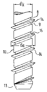
The screw presented in fig. 15 is designed as a thread drill-
ing tool to make a tapped hole in concrete, masonry, and the
like. The tool has a clamping portion 1 which is quadrilateral
or multisided in cross section and by which the tool may be
clamped in a drill, next a smooth shank portion 2 circular in
cross section, an adjacent guide portion 3 provided with a
thread 4, and a thread lead portion 5 which is slightly conic-
al, having a cone angle 6 of between 1.5 ° and 3 °, preferably
about 2 °, and on which the thread 4 continues up to the end
face 6 of the tool.
In the tool illustrated, the length 1 of the thread lead por-
tion 5 is to the length k of the guide portion 3 like approxi-
mately 4:5. This results from the small preferred cone angle d
- 2 ° of the thread lead portion 5. It is important that the
thread 4 start directly at the surface 6 of the tool facing
the bore 7 in the concrete in order for the thread cutting
process to be able to begin at once as the tool is sunk into
the bore 7.
For the sake of simplicity, fig. 15 does not show the cutting
teeth which may be arranged around the thread burr as in the
other embodiments and which were explained already with
ref erence to f igs . 3 to 14 .
~1~~8~Q
Thread drilling tools usually are made of metal. Thus the
forming of the cutting teeth in the thread burr may be dif-
ficult. Alternatively, therefore, cutting teeth made by par-
axial profile grooves and extending approximately for the
thread height h of the thread 4 may be provided instead of the
cutting teeth described. Such cutting teeth also may be
provided together with the cutting teeth discussed above with
reference to figs. 3 to 14.
As the tool is turned into a hole 7 predrilled in the con-
crete, the wedge-shaped teeth of the thread 4 are pressed into
the concrete under great pressure. Due to the wedging effect
of the teeth, local overstressing of the concrete occurs and
that leads to the formation of fracture scars and finally to
chipping off of the concrete. It is by this severing mechanism
that the desired internal thread finally is formed in the con-
crete.
A screw provided with a thread according to figs. 1 to 14 then
may be turned directly into the internal thread thus obtained
and, without any meditation of a dowel, it will provide good
fastening of parts to be held against the concrete or masonry.
Such a screw, however, does not need any cutting teeth as
described with reference to figs. 3 to 14 and designated 16.