Sélection de la langue

Search

Sommaire du brevet 2161851 

Énoncé de désistement de responsabilité concernant l'information provenant de tiers

Une partie des informations de ce site Web a été fournie par des sources externes. Le gouvernement du Canada n'assume aucune responsabilité concernant la précision, l'actualité ou la fiabilité des informations fournies par les sources externes. Les utilisateurs qui désirent employer cette information devraient consulter directement la source des informations. Le contenu fourni par les sources externes n'est pas assujetti aux exigences sur les langues officielles, la protection des renseignements personnels et l'accessibilité.

Disponibilité de l'Abrégé et des Revendications

L'apparition de différences dans le texte et l'image des Revendications et de l'Abrégé dépend du moment auquel le document est publié. Les textes des Revendications et de l'Abrégé sont affichés :

  • lorsque la demande peut être examinée par le public;
  • lorsque le brevet est émis (délivrance).
(12) Brevet: (11) CA 2161851
(54) Titre français: TAMBOUR LAVEUR A ALIMENTATION SOUS PRESSION
(54) Titre anglais: PRESSURE WASHER DRUM
Statut: Périmé et au-delà du délai pour l’annulation
Données bibliographiques
(51) Classification internationale des brevets (CIB):
  • D21D 5/06 (2006.01)
  • B01D 33/067 (2006.01)
  • D21C 9/06 (2006.01)
(72) Inventeurs :
  • TAYLER, MARK (Canada)
  • GADALA, MOHAMED S. (Canada)
  • HODGINS, GARY (Canada)
(73) Titulaires :
  • TRISTAR INDUSTRIES LTD.
(71) Demandeurs :
  • MARK TAYLER (Canada)
  • MOHAMED S. GADALA (Canada)
  • GARY HODGINS (Canada)
(74) Agent: OYEN WIGGS GREEN & MUTALA LLP
(74) Co-agent:
(45) Délivré: 1999-06-01
(22) Date de dépôt: 1995-10-31
(41) Mise à la disponibilité du public: 1997-05-01
Requête d'examen: 1996-04-01
Licence disponible: S.O.
Cédé au domaine public: S.O.
(25) Langue des documents déposés: Anglais

Traité de coopération en matière de brevets (PCT): Non

(30) Données de priorité de la demande: S.O.

Abrégés

Abrégé anglais


In prior pressure washer drums, the filter deck was
supported on the central shaft by spokes welded to the central
hub which was in turn welded to the shaft. The extreme forces
caused premature failure of the welded joints. The present
invention provides a pressure washer drum in which sandwic-
hed parallel plates having an array of apertures replace the
spokes and central pipe and journals are supported on the hub
by a bolting system rather than by welding.

Revendications

Note : Les revendications sont présentées dans la langue officielle dans laquelle elles ont été soumises.


- 7 -
WHAT IS CLAIMED IS:
1. A rotatable filter drum, for use in washing cellulose
pulp under pressure comprising:
i) a hub at either end of said drum;
ii) a central shaft removably secured at either end
thereof to said hub;
iii) a cylindrical, perforated deck for supporting
a layer of pulp, supported on a plurality of annular
rings coaxial to said shaft and longitudinal bars
parallel to said shaft;
iv) two parallel plates secured at their inner ends
to each hub respectively and at their outer edges
to said deck, each said plate having a spaced array
of openings;
v) a plurality of radially extending ribs extend-
ing longitudinally between said plates;
vi) a circular ring extending between and adjacent
the outer ends of said plates, and provided with a
plurality of apertures to permit fluid flow there-
through; and
v) a journal coaxially secured to the outer end of
each said hub.
2. The drum of claim 1 wherein said central shaft is
secured to said hubs by locking devices.
3. The drum of claim 1 wherein said circular ring has
an extended tapered inner edge secured to said longitudinal
bars.
4. The drum of claim 1 wherein said deck in the region
adjacent said circular ring has an increased number of said
longitudinal bars relative to the rest of said deck.

Description

Note : Les descriptions sont présentées dans la langue officielle dans laquelle elles ont été soumises.

1618~1 -
PRESSURE W~FR~ DRUM
Technical Field
The invention relates to the field of pressure
washers used in the processing of cellulose fibre pulp, and
more particularly to an improved drum design for pressure
washers.
Backqround Art
Rotary drum washers or filters are used in the
manufacture of paper products from pulp. A slurry of pulp
fibres suspended in water and various chemical additives is
formed from wood chips. A sheet of pulp is formed from the
slurry on the surface of a large drum by rotating the drum
through the pulp slurry. The pulp sheet is then washed and
de-watered on the outer surface of the drum, which has a
perforated deck. The pulp sheet is then separated from the
drum for further processing. Two general types of rotary drum
washers are in common use - vacuum washer drums and pressure
washer drums. In the vacuum washer drum, low pressure is
maintained between an inner and an outer deck to draw the
filtrate from the pulp sheet towards the centre of the drum.
In the pressure washer drum, the drum is housed in a pressure
chamber so that the exterior of the drum is maintained at a
higher pressure than the interior, to force the filtrate
through the filter deck of the drum. A prior art pressure
washer is disclosed in United States Patent number 3,487,941
issued January 6, 1970 to Rauma-Repola Oy.
In pressure washer drums, the cylindrical filter
deck has typically been supported on the axis of rotation by
a number of annular spokes at either end of the drum. Such
spokes are subjected to considerable forces, due to the
combined weight of the drum and the external pressure on the
surface of the drum, as well as rotational forces. For this
reason the spokes are sub]ect to premature failure, which

~ '- 21 618Sl
-- 2
results in a costly shutdown of the pulp processing facility
in order to replace the drum, and expensive repairs. There
is therefore a need for an improved design for the pressure
- washer drum which avoids such premature failure.
Disclosure of Invention
The invention provides a rotatable filter drum, for
use in washing cellulose pulp under pressure comprising:
i) a hub at either end of the drum;
ii) a central shaft removably secured at either end
thereof to the hub;
iii) a cylindrical, perforated deck for supporting
a layer of pulp, supported on a plurality of annular
rings coaxial to the shaft and longitudinal bars
parallel to the shaft;
iv) two parallel plates secured at their inner ends
to each hub respectively and at their outer edges
to the deck, each the plate having a spaced array
of openings to permit fluid flow therethrough;
v) a plurality of radially extending ribs extend-
ing longitudinally between the plates;
vi) a circular ring extending between and adjacent
the outer ends of the plates, and provided with a
plurality of apertures to permit fluid flow there-
through; and
v) a journal coaxially secured to the outer end of
each the hub.
~0 Brief Description of Drawinqs
In drawings which illustrate a preferred embodiment
of the invention:

i l 8 ~ 1
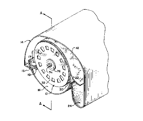
Fig. 1 is a perspective view of the pressure washer drum
of the invention shown mounted for rotation in a pressure
washer, with the end seal plate removed;
Fig. lA is a cross-section along lines A-A of Fig. 1,
with the end seal plate in place;
Fig. 2 is an end view of the pressure washer drum
according to the invention, with the shroud removed and
the interior structure shown in phantom outline;
Fig. 3 is a cross-section taken along lines 3-3 of Figure
1, with the central section omitted along broken lines;
Fig. 3A is a detail view in cross-section taken at line
C of Figure 3; and
Fig. 4 is a detail view of the hub of the invention.
Best Mode(s) For Carrying Out the Invention
With reference to Fig. 1, the pressure washer drum
of the invention is designated by reference numeral 10. It
is suspended in the usual way on journals 74, 75 for rotation
within a pressurized chamber 14, so that the interior of the
drum 10 is at a lower pressure than the exterior. The pulp
slurry is pumped into the inlet headbox 15 at a consistency
of 2-4~ BD. The pulp slurry forms a mat by dewatering as it
travels with the drum through the forming zone 17. At the end
of the forming zone, the pulp mat is able to dewater in a
relatively short time period compared to a vacuum washer due
to the high pressure differential between the forming zone and
the inside of the drum. Pressure ranges from 1.0 to 5.0 psig.
A lip seal or bottom seal 19 placed across the full width of
the drum prevents flow of pulp into the bottom of the vat and
forces all of the pulp flow to rotate clockwise around the
drum upon leaving the inlet headbox. Upon rotation of the
drum 10 therefore a sheet 18 of pulp fibres adheres to the
surface 20 of the drum.

~ - 2161851
-
-- 4
Surface 20 of the drum is perforated to permit
filtrate to pass through the surface of the drum, to fall into
the interior of the drum where it collects with the liquor in
the tank 16. As the drum rotates in the clockwise direction,
as viewed in Fig. 1, surface 20 of drum 10 picks up the sheet
18 of pulp fibres which, after being drained of the filtrate,
is separated from the surface 20 of drum 10 by knife edge 22
and falls into trough 24 for further processing.
With reference to Fig. 2 and 3, the outer surface
20 of the drum consists of a perforated screen 26 which is
supported on parallel circular ribs, referred to as flyrings
28 and longitudinal bars 30. The drum deck is supported by
the end plates 32, 34. End plates 32, 34 are each formed of
two parallel circular plates of 3/4-inch steel, exterior end
plates 40 and 44 and interior end plates 42 and 46. Radial
ribs 48 extend between the exterior and interior end plates.
Circular rings 50, 52 join the ends of each pair of end
plates. The inner edge 51, 53 of rings 50, 52 is extended and
machined to a taper to provide a smooth transition of forces
to the longitudinal bars 30. In addition there are additional
longitudinal bars 31 between longitudinal bars 30 extending
between exterior end plates 40, 44 and the second sets 29 of
flyrings 28 to aid in the smooth transition from the end
component sub-assembly 23 to the central cage subassembly of
the drum.
A two-by-two array of four holes 55 is provided in
circular rings 50, 52 in each compartment 54 formed by deck
20, ring 50 or 52 and adjacent longitudinal bars 30 and
flyrings 28. In this way, the filtrate is permitted to flow
from the compartments 54 into the space 56 between the
interior and exterior plates 40, 44 and 42, 46. Both interior
and exterior plates are provided with an array of openings 60
to permit the flow of filtrate between the interior of the
drum and tank 13. Tank 13 is separated from region 16 by the

'~ 216 1 ~51
-- 5
end seal subassembly 21. Openings 62 are larger to permit
workman access. The size and location of openings 60, 62 is
selected to provide the maximum strength of the end plates at
the points of highest stress while permitting the necessary
flow of liquid. The entire end subassembly component 23
consisting of ribs 56 and end plates is thermally stress
relieved.
Fig. 4 shows the hub design in greater detail. Pipe
12 has stub shafts 64 of reduced diameter. End plates 40, 42,
44, 46 are welded to hub 66 at locations 68. Hub 66 has a
hollow central channel 67. A ring 70 is bolted to the end
of hub 66 and retains ring seal 72 to seal the hub against
stub shaft 64. Stub shaft 64 is inserted as shown in centre
67 of hub 66 and one RINGFEDERTM locking device 69 is inserted
between the wall of channel 67 and the surface of end 64 and
is tightened to secure hub 66 to end 64. Journal 74 at flange
location 76 is bolted to hub 66 by bolts 78. A shroud 80 is
welded to packing sleeve 83 to cover bolts 78. Journal 74 is
mounted in bearing assembly 85 in stuffing box 84 secured to
wall 86 of pressure chamber 14. Ring 88 at the outer end of
wall 86 supports an annular end seal 90 of TEFLONTM or the like
which has sealing and sliding contact with the outer edge 92
of end plates 40, 44.
By the foregoing design, pipe 12 is secured to hub
66 without welding and the welds joining the hub to the end
plates are remote from the axis at a region of lower stresses.
In the previous spoked designs, the welds between the spokes
and the hub were close to the axis and failure was typically
at that point. The use of plates rather than spokes also
serves to spread the stresses over the area of the plates.
The dissipation of stresses to the longitudinal bars is
further improved by the tapering of extended edges 51 of rings
50, 52 and the installation of additional longitudinal bars
31 in the area adjacent to rings 50, 52. The use of a bolt-

- ~1618~1
-- 6
on style journal allows the journal to be removed from the
drum for maintenance, whereas in prior designs the entire drum
had to be removed.
As will be apparent to those skilled in the art in
the light of the foregoing disclosure, many alterations and
modifications are possible in the practice of this invention
without departing from the spirit or scope thereof. Accord-
ingly, the scope of the invention is to be construed in accor-
dance with the substance defined by the following claims.

Dessin représentatif
Une figure unique qui représente un dessin illustrant l'invention.
États administratifs

2024-08-01 : Dans le cadre de la transition vers les Brevets de nouvelle génération (BNG), la base de données sur les brevets canadiens (BDBC) contient désormais un Historique d'événement plus détaillé, qui reproduit le Journal des événements de notre nouvelle solution interne.

Veuillez noter que les événements débutant par « Inactive : » se réfèrent à des événements qui ne sont plus utilisés dans notre nouvelle solution interne.

Pour une meilleure compréhension de l'état de la demande ou brevet qui figure sur cette page, la rubrique Mise en garde , et les descriptions de Brevet , Historique d'événement , Taxes périodiques et Historique des paiements devraient être consultées.

Historique d'événement

Description Date
Inactive : CIB de MCD 2006-03-12
Le délai pour l'annulation est expiré 2003-10-31
Lettre envoyée 2002-10-31
Accordé par délivrance 1999-06-01
Inactive : Page couverture publiée 1999-05-31
Préoctroi 1999-02-24
Inactive : Taxe finale reçue 1999-02-24
Lettre envoyée 1998-08-27
Un avis d'acceptation est envoyé 1998-08-27
Inactive : Approuvée aux fins d'acceptation (AFA) 1998-08-07
Inactive : Renseign. sur l'état - Complets dès date d'ent. journ. 1998-06-16
Inactive : Dem. traitée sur TS dès date d'ent. journal 1998-06-16
Demande publiée (accessible au public) 1997-05-01
Toutes les exigences pour l'examen - jugée conforme 1996-04-01
Exigences pour une requête d'examen - jugée conforme 1996-04-01

Historique d'abandonnement

Il n'y a pas d'historique d'abandonnement

Taxes périodiques

Le dernier paiement a été reçu le 1998-06-17

Avis : Si le paiement en totalité n'a pas été reçu au plus tard à la date indiquée, une taxe supplémentaire peut être imposée, soit une des taxes suivantes :

  • taxe de rétablissement ;
  • taxe pour paiement en souffrance ; ou
  • taxe additionnelle pour le renversement d'une péremption réputée.

Veuillez vous référer à la page web des taxes sur les brevets de l'OPIC pour voir tous les montants actuels des taxes.

Historique des taxes

Type de taxes Anniversaire Échéance Date payée
Requête d'examen - générale 1996-04-01
TM (demande, 2e anniv.) - générale 02 1997-10-31 1997-06-27
TM (demande, 3e anniv.) - générale 03 1998-11-02 1998-06-17
Taxe finale - générale 1999-02-24
TM (brevet, 4e anniv.) - générale 1999-11-01 1999-10-04
TM (brevet, 5e anniv.) - générale 2000-10-31 2000-09-08
TM (brevet, 6e anniv.) - générale 2001-10-31 2001-10-17
Titulaires au dossier

Les titulaires actuels et antérieures au dossier sont affichés en ordre alphabétique.

Titulaires actuels au dossier
TRISTAR INDUSTRIES LTD.
Titulaires antérieures au dossier
GARY HODGINS
MARK TAYLER
MOHAMED S. GADALA
Les propriétaires antérieurs qui ne figurent pas dans la liste des « Propriétaires au dossier » apparaîtront dans d'autres documents au dossier.
Documents

Pour visionner les fichiers sélectionnés, entrer le code reCAPTCHA :


Pour visualiser une image, cliquer sur un lien dans la colonne description du document. Pour télécharger l'image (les images), cliquer l'une ou plusieurs cases à cocher dans la première colonne et ensuite cliquer sur le bouton "Télécharger sélection en format PDF (archive Zip)" ou le bouton "Télécharger sélection (en un fichier PDF fusionné)".

Liste des documents de brevet publiés et non publiés sur la BDBC .

Si vous avez des difficultés à accéder au contenu, veuillez communiquer avec le Centre de services à la clientèle au 1-866-997-1936, ou envoyer un courriel au Centre de service à la clientèle de l'OPIC.


Description du
Document 
Date
(aaaa-mm-jj) 
Nombre de pages   Taille de l'image (Ko) 
Description 1996-03-19 6 236
Dessins 1996-03-19 5 144
Revendications 1996-03-19 1 34
Page couverture 1999-05-27 1 38
Page couverture 1996-03-19 1 15
Abrégé 1996-03-19 1 14
Dessins 1997-06-09 5 154
Page couverture 1998-07-08 1 15
Dessin représentatif 1997-10-22 1 18
Dessin représentatif 1999-05-27 1 16
Rappel de taxe de maintien due 1997-07-01 1 111
Avis du commissaire - Demande jugée acceptable 1998-08-27 1 166
Avis concernant la taxe de maintien 2002-11-28 1 174
Correspondance 1999-02-24 1 40
Correspondance 1996-05-13 1 58