Note : Les descriptions sont présentées dans la langue officielle dans laquelle elles ont été soumises.
2162308
PA-7216-0-RE-USA
S_PEC_IFIC_ATION
TITLE
"EVAPORATOR FAN CONTROL FOR A REFRIGERATOR"
BACKGROUND OF THE INVENTION
This invention relates generally to refrigerator air circulation systems and
more
particularly to an improved air circulation system for independently
controlling the operation
to of an evaporator fan based on the status of either the fresh food
compartment or the freezer
compartment of a refrigerator.
Conventional dual compartment refrigerators of the forced air circulation type
utilize a
single evaporator and an evaporator fan for cooling a freezer compartment
thereof. The
freezer compartment is coupled by a plurality of air passages through a
divider wall to a fresh
15 food compartment. An air baffle is located within the fresh food
compartment air inlet
passage wherein the baffle is operable to control the passage of refrigerated
air into the fresh
food compartment.
Typically, the operation of the compressor and evaporator fan is controlled by
a single
thermostat which may be positioned in either the fresh food compartment or the
freezer
2o compartment. When the thermostat calls for additional cooling, the
evaporator fan, a
compressor and a condenser fan are all energized.
It has been found desirable, however, to provide a refrigerator having a fresh
food
compartment and a freezer compartment wherein the respective compartments are
cooled
independently from each other. In this configuration, independent operation of
the evaporator
2s fan is desired such that the evaporator fan may be energized in response to
either the fresh
food compartment temperature or the freezer compartment temperature. Further,
in this type
of refrigerator configuration, it is desirable to selectively operate the
baffle to only allow air
flow into the fresh food compartment when cooling thereof is required.
-1-
2I6~3~8
PA-7216-0-RE-USA
U.S. Patent No. 4,819,442, to Sepso et al., discloses a refrigerator system
wherein a
temperature sensing unit is interconnected with a baffle to control the
position of the baffle in
relation to the temperature sensed by the temperature sensing unit. A switch
is operatively
associated with the baffle for causing a fan to operate only when the valve
member is in a
certain open position. This system, however, provides no teaching for
operating the
evaporator fan when either a fresh food compartment or a freezer compartment
is calling for
cooling. Further, this system is relatively complicated and expensive.
U.S. Pat. No. 4,843,833, to Polkinghorne, discloses a refrigerator having an
electronic
control receiving inputs from temperature sensors disposed in the freezer
compartment and
to fresh food compartment, respectively. When the freezer is detected to have
a temperature
exceeding a high temperature limit, the control operates to energize the
compressor and
evaporator fan. The control further operates to open or close a fresh food
baffle dependent on
the sensed temperature in the fresh food compartment. This system, however,
requires
relatively expensive electronics and is relatively complicated.
i5 U.S. Pat. No. 4,732,010, to Linstromberg et al., discloses a refrigerator
having an
electronic control receiving inputs from temperature sensors disposed in the
freezer
compartment and fresh food compartment. When the temperature in the fresh food
compartment is above a desired fresh food temperature limit, the electronic
control operates to
open a fresh food bale and energize an evaporator fan. The control further
operates to close
2o the baffle when the fresh food compartment is at or below the desired fresh
food compartment
temperature. When the freezer compartment temperature is above a high
temperature limit,
the control operates to energize a compressor and the evaporator fan. This
system, however,
also requires relatively expensive electronics and is relatively complicated.
It would be an improvement in the art, therefore, if a relatively simple
system were
25 provided for independently operating to cool a freezer compartment and
fresh food
compartment. Specifically, it would be an improvement if an electro-mechanical
control
system were provided for independently operating an evaporator fan and a fresh
food baffle
-2-
216 2 3 0 8 PA-~216-0-RE-USA
for independently controlling the temperatures of a fresh food compartment and
freezer
compartment.
SUMMARY OF THE INVENTION
Accordingly, one object of the present invention is to provide a refiYgeration
system for
independently cooling a freezer compartment and a fresh food compartment.
Another object is to provide a refrigeration system for controlling the
operation of an
evaporator fan based on the status of either the fresh food compartment or the
freezer
to compartment.
Still another object of the present invention is to provide a simple electro-
mechanical
system control system for a refrigerator for independently operating an
evaporator fan in
response to the status of either the fresh food compartment or the freezer
compartment.
Still another object is to provide a refi-igerator having an evaporator fan
control system
15 having a switch operatively associated with the baffle for controlling the
energization of an
evaporator fan.
According to the present invention, the foregoing and other objects are
attained by a
refi-igerator having a cabinet defining a first compartment and a second
compartment separated
from each other by a divider wall wherein the divider wall has an air passage
for
2o communicating between the first and second compartments. The refrigerator
further includes
an evaporator disposed in the first compartment, a compressor fluidly
connected with the
evaporator for moving refi-igerant therethrough, and an evaporator fan for
moving air over the
evaporator. A first thermostat senses temperature within the first compartment
and a second
thermostat senses temperature within the second compartment. An evaporator fan
and bai~le
25 control system is provided including a baffle disposed within the air
passage and being
positionable in an open or closed position for selectively opening and closing
the air passage.
A switch is operatively associated with the baffle for connecting the first
thermostat and the
evaporator fan in series with a power supply when the baffle is in the closed
position and for
-3-
21 b 2 3 0 8 PA-7216-0-RE-USA
further connecting the second thermostat and the evaporator fan in series with
the power
supply when the baffle is in the open position.
The baffle control system includes a cam driven by a baffle motor wherein the
cam is
coupled to a baffle for moving the baffle between an open and closed position.
A plurality of
switches, operated by the cam, are provided for controlling the energization
of the motor such
that the baffle is opened when the fresh food thermostat indicates cooling of
the fresh food
compartment is desired and the baffle is closed when the fresh food
compartment does not
require cooling.
l0 BRIEF DESCRIPTION OF THE DRAWINGS
FIG. 1 is a front elevational view of a refrigerator having an air baffle
embodying the
invention, the compartment doors being omitted to facilitate an illustration
of the components
therein;
FIG 2 is an plan view of a baffle system according to the invention;
FIG. 3 is a partly cut away side elevational view of the baffle of FIG. 2;
FIG. 4 is a view taken along lines 4-4 of FIG. 3 showing the baffle in a
closed position;
FIG. S is a view taken along lines 4-4 of FIG. 3 showing the baille in an open
position;
FIG. 6 is an enlarged sectional view taken along lines 6-6 in FIG. 4;
2o FIG. 7 is an enlarge sectional view taken along lines 7-7 in FIG. 5;
FIG. 8 is an electrical schematic of an evaporator fan and baffle control
system of the
present invention, wherein the baffle is positioned in a closed position;
FIG. 8a is an alternative electrical schematic of an evaporator fan and bafBe
control
system of the present invention, wherein the baffle is positioned in a closed
position;
FIG. 9 is a partly cut away bottom elevational view of the baffle of FIG. 2
showing the
baffle in a closed position;
FIG. 10 is an electrical schematic of a evaporator fan and baffle control
system of the
present invention, wherein the baffle is positioned in an open position; and
2162308
PA-7216-0-RE-USA
FIG 11 is a partly cut away bottom elevational view of the baffle of FIG. 2
showing the
baffle in an open position.
DETAILED DESCRIPTION OF THE PREFERRED EMBODWENT
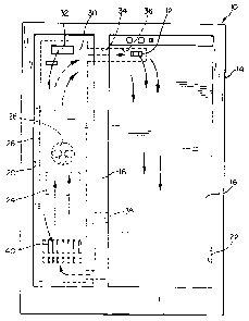
Referring to FIG. 1, a refrigeration apparatus, such as a refi-
igerator/freezer 10,
includes an air baffle 12 according to the present invention. The invention is
shown utilized
with a side-by-side refrigerator/freezer. However, other types of
refrigeration apparatus may
be used in conjunction with the air baffle 12 of the present invention, as
will be obvious to
to those skilled in the art.
The refrigerator/freezer 10 includes cabinet 14 housing a conventional liner
16 therein,
with suitable insulation provided between the liner 16 and the cabinet 14. The
liner 16
includes a plurality of wall portions, as is well known, and may be of one
piece construction or
of multiple piece construction, as necessary or desired. The
refrigerator/freezer 10 includes an
15 insulating separator or divider wall 18 which may utilize the liner wall
portions. The cabinet
14, liner 16 and divider wall 18 together define a below-freezing, or freezer,
compartment 20
and a fresh food, or above-freezing, compartment 22. Suitable doors (not
shown) are
provided for selective access to the freezer and fresh food compartments 20
and 22.
The freezer and fresh food compartments 20 and 22 are cooled by circulating
2o refrigerated air therethrough which has been refi-igerated as a result of
being passed in heat
exchange relation with a conventional evaporator 24. An evaporator fan 26
draws air across
the evaporator 24 with the cooled air passing through a duct 28 behind a rear
wall 30 of the
freezer compartment 20 and further through a freezer compartment air inlet 32.
The duct 28
is also in communication with a scoop, or passage, 34 in the separator 18. The
passage 34 is
25 in communication with an air duct 36 in the upper rear section of the fresh
food compartment
22, which duct 36 includes a fresh food compartment air inlet opening (not
shown). The
selectively positionable baffle 12 overlies the air inlet opening and is
operated by a control
-5-
216 2 3 0 8 PA'~216-0-RE USA
described below to control the passage of refrigerated air into the fresh food
compartment 22.
The passage 34, the duct 36 and the opening collectively define an air inlet
passageway.
Although the baffle 12 is illustrated overlying the air inlet opening, the
baffle 12 could
be disposed at various positions within the passage 34 or the duct 36 as is
obvious to those
skilled in the art.
Refrigerated air that passes through the passage 34 is discharged through air
inlets of
the baffle 12 to circulate within the fresh food compartment 22 and
subsequently return to the
freezer duct 28 through a return air outlet duct, or passage 38 located in the
separator 14 at
the bottom rear of the fresh food compartment 22.
1o The refrigerated air in the freezer compartment 20 returns to the duct 28
at a freezer
compartment air outlet 40 and mixes with the air returned from the fresh food
compartment
22. The mixed air is drawn by the evaporator fan 26 across the evaporator 24
during a
cooling unit on cycle to remove heat therefrom and recirculate the air in the
compartments 20
and 22.
In addition to the evaporator 24 and the evaporator fan 26, the refrigeration
apparatus
10 includes connected components such as a compressor 39 and a condenser fan
41, shown in
FIG. 8, and a condenser and a defrost heater, not shown, as is well known.
Refernng to FIGS. 2 and 3, the baffle 12 can be seen to include a fixed plate
42 and a
slide plate 44.
2o The fixed plate 42 is of one-piece molded plastic construction and is
generally
rectangular shaped. The fixed plate 42 includes a plurality of longitudinally
spaced, laterally
extending apertures 48 therethrough. The apertures 48 are provided for
enabling refrigerated
air to enter the fresh food compartment 22. An actuator mounting end 50 of the
fixed plate 42
includes no such apertures 48.
The slide plate 44 is also of generally rectangular construction, but is of
smaller size
than the fixed plate 42. The slide plate 44 includes a plurality of apertures
52 therethrough
corresponding to the apertures 48 in the fixed plate 42.
it L PA-7216-0-RE-USA
The slide plate 44 is slidably mounted to the fixed plate 42 permitting
straight line
reciprocal motion of the slide plate 44 with respect to the fixed plate 42.
Specifically, the
fixed plate 42 includes a plurality of outwardly extending L-shaped slide
members 54 for
laterally constraining the slide plate 44 with respect to the fixed plate 42
while allowing
longitudinal movement. The L-shaped members 54 are laterally spaced apart a
distance
slightly greater than the width of the slide plate 44 and define a track
within which the
movable plate 44 can slide. It can be understood, therefore, that the slide
plate 44 is slidably
movable relative to the fixed plate 42 between an open position, with its
apertures 52 in
alignment with the fixed plate apertures 48 to permit refiigerated air to flow
into the fresh
1o food compartment, and a closed position wherein the apertures 48 and 52 are
in disalignment
to prevent the refrigerated air from entering the fresh food compartment 22.
Mounted to the fixed plate 42 is a slide plate drive system 60 including a
motor 62, a
gear reduction mechanism 64 and a cam 68. The motor is mounted to the gear
reduction
mechanism which operates in a known manner to reduce the motor speed output.
The gear
reduction mechanism 64 is mounted to a housing 66 which is mounted to the
fixed plate 42.
The cam member 68, disposed within the housing 66, is interconnected with the
gear
reduction drive output 69 and includes a first, second and third control
surfaces, 68a, 68b and
68c, respectively.
As shown in FIGS. 4 and 5, the cam 68 operates to drive the slide plate such
that the
2o baffle may be selectively positioned in the closed or open position. The
first surface 68a of the
cam 68 is disposed within a shaped slot 70 provided on slide plate 44. The
shaped slot 70
includes a first contact point 70a and a second contact point 70b. In
operation, rotation of the
cam 68 causes the first control surface 68a to engage either the first or
second contact point
70a or 70b, respectively, for moving the slide plate 44 relative to the fixed
plate 42. As shown
in FIG. 4, the first control surface 68a is positioned such that the slide
plate is in a closed
position. In FIG. 5, the cam 68 is shown rotated 180 angular degrees from FIG.
4, whereby
the first control surface 68a has engaged the second contact point 70b for
moving the slide
plate 44 to an open position.
_7_
216 2 3 0 8 PA-7216-0-RE-USA
Turning now to FIGS. 6 and 7, details of the fixed plate and the slide plate
44 are
shown. As described above, the slide plate 44 is slidably mounted to the fixed
plate 42
wherein a top surface 72 of the fixed plate and a bottom surface 74 of the
slide plate 44 are
slidably disposed adjacent each other. As can be readily understood by one
skilled in the art,
for the baffle 12 to effectively prevent air flow through the duct 34 when the
slide plate 44 is
in the closed position, the top surface 72 and the bottom surface 74 must
substantially contact
each other to provide a seal between the slide plate 44 and fixed plate 42. To
this end, the top
surface 72 and the bottom surface 74 are preferably flat to within 0.25mm such
that the gap
between the two surfaces, 72 and 74, may be limited to no more than 0.15 mm.
1o This intimate contact between the top surface 72 and the bottom surface 74,
however,
may contribute to frost forming on the baffle 12 and bridging between the
fixed plate 42 and
slide plate 44, thereby inhibiting the movement of the slide plate 44 relative
to the fixed plate
42. To overcome this problem, the front edge 76 of the slide plate 44 as well
as the side edges
52a and 52b of the slide plate apertures 52 and the side edges 48a and 48b of
the fined plate
apertures 48 are chamfered such that the respective edges provide a structure
for removing
frost which may accumulate on the baille. These edges operate to remove frost
in both
directions of slide plate movement. Preferably, each of these edges, 76, 52a,
52b, 48a and
48b, respectively, is provided with a 45 degree chamfer such that each edge
presents a sharp
edge for contacting the facing plate and a 45 degree slope for forcing away
frost build up.
2o In FIGS. 8-11, a unique and simple evaporator fan control system and baffle
control
system of the present invention are shown. The evaporator control system is
such that
evaporator fan 26 may be energized when either the fresh food compartment 22
or the freezer
compartment 20 require cooling. The baffle door control system is such that
when the fresh
food compartment requires cooling, the baffle 12 is open. However, when
cooling of the fresh
food compartment is not required, the baffle 12 is closed.
Turning now to FIG. 8, a freezer thermostat 80 and a fresh food thermostat 82
are
shown. As is known, the freezer thermostat 80 senses temperature in the
freezer compartment
20 and the fresh food thermostat 82 senses temperature in the fresh food
compartment 22.
_g_
216 2 3 0 S pp-7216-0-RE-USA
The freezer thermostat 80 is electrically connected in series with the
compressor 39
and the condenser fan 41 such that when the freezer thermostat 80 is closed,
indicating that
freezer cooling is required, the compressor 39 and condenser fan 41 are
energized. The fresh
food thermostat is connected in series with the baffle or air door motor 62
through a first
switch 84 and a second switch 86 wherein the switches 84 and 86 are connected
in parallel.
Further, a third switch 88 is provided connected in series between the fresh
food thermostat 82
and the evaporator fan 26. The third switch 88 is also connected in series
between the freezer
thermostat and the evaporator fan 26. All of the switches, 84, 86 and 88
respectively, are
operated by the cam 68.
io In FIG. 9, the switches 84, 86 and 88 are shown assembled within the
housing 66. As
shown, the second control surface 68b engages a cam follower 90 for
selectively operating the
fast switch 84. The second control surface 68b additionally engages a cam
follower 94 for
selectively operating the second switch 86. Further, the third control surface
68c engages a
cam follower 96 for operating the third switch 88.
During operation, when the fresh food compartment is at or below the desired
fresh
food temperature, the fresh food thermostat electrical contacts are oriented
in a position
wherein a current path is provided through the contacts 82a and 82b. When the
contacts are
oriented in this fashion, the baffle is positioned in a closed position, as
shown in FIG. 9. It can
be seen that in this condition, the cam follower 90 resides in a recess 92
provided on the
2o second control surface 68b such that the contacts 84a and 84b are not
engaged. Additionally,
the cam follower 94 is engaged by the second control surface 68b such that
switch 86 is closed
wherein contacts 86a and 86b are engaged. Still further, the cam follower 96
is positioned by
the third control surface 68c such that contacts 88a and 88b are engaged
thereby connecting
the evaporator fan in series with the freezer thermostat 80.
In the baffle closed condition, therefore, the freezer thermostat 80 controls
the
operation of the evaporator fan 26, the compressor 39, and the condenser fan
41 responsive to
the cooling demands of the freezer compartment 20.
-9-
216 2 3 0 8 PA-7216-0-RE-USA
When the temperature in the fresh food compartment 22 rises above the desired
fresh
food temperature, the fresh food thermostat 82 opens contacts 82a and 82b and
closes
contacts 82a and 82c. Under this condition, the baille motor 62 is energized
through the
second switch 86 which is in the closed position as described above.
Energization of the
motor 62 causes the cam 68 to rotate, closing the first switch 84 and moving
the slide door 44
from a closed toward an open position. As further described above, 180 degree
rotation of
the cam 68 moves the baffle 12 from a completely closed position to a
completely open
position. In the completely open position, the recess 92 provided on the
second control
surface 68b operates to open the second switch 86, thereby deenergizing the
motor 62.
1o Further, the third control surface drives the third switch 88 to close
contacts 88c and 88b
wherein the evaporator fan 26 is energized through the fresh food thermostat
82.
FIGS. 10 and 11, illustrate the switch configuration when the fresh food
compartment
22 is calling for cooling and the baffle is in a completely open position. In
this condition, the
cam follower 90 is engaged by the second control surface 68b such that the
first switch 84 is
closed. The cam follower 94, however, resides in the recess 92 such that the
second switch 86
is open. Further, the cam follower 96 resides in a recess 98 provided on the
third control
surface 68c such that the third switch 88 is oriented to close contacts 88b
and 88c.
In the baffle open condition, therefore, the fresh food thermostat 82 controls
the
operation of the evaporator fan 26. As described above, when the fresh food
thermostat calls
2o for additional cooling for the fresh food compartment, the baffle 12 is
positioned in an open
position. It can be understood, therefore, that whenever the baffle 12 is
open, the evaporator
fan is energized.
When the temperature in the fresh food compartment 22 moves below the desired
fresh
food temperature, the fresh food thermostat 82 opens contacts 82a and 82c and
closes
contacts 82a and 82b. Under this condition, the baffle motor 62 is energized
through the first
switch 84 which is in the closed position. Energization of the motor 62 causes
the cam 68 to
rotate, closing the second switch 86 and moving the slide door 44 from an open
toward a
closed position. As described above, 180 degree rotation of the cam 68 moves
the baffle 12
-10-
2 i 6 2 3 0 8 PA-7216-0-RE-USA
from a completely open position to a completely closed position. In the
completely closed
position, the recess 92 provided on the second control surface 68b operates to
open the first
switch 84, thereby deenergizing the motor 62. Further, the third control
surface drives the
third switch 88 to close contacts 88a and 88b wherein the evaporator fan 26 is
connected in
series with the freezer thermostat 80.
With regard to temperature control of the freezer compartment 20, it can be
understood from the above description that when the baffle 12 is in a closed
position and the
temperature in the freezer compartment 20 moves above the desired freezer
temperature, the
freezer thermostat 80 closes, energizing the compressor 39, condenser fan 41
and the
to evaporator fan 26. However, when the baffle 12 is open, the evaporator fan
26 is energized
through the contacts of the fresh food thermostat 82. With the baffle 12 open,
therefore, the
freezer thermostat 80 operates to energize only the compressor 39 and the
condenser fan 41.
An alternative embodiment for the present invention is illustrated in Fig. 8a
wherein
switch 100 has been added for providing an additional control feature to the
present invention.
As contemplated by the inventors, switch 100 is disposed between switch 88 and
the
evaporator fan 26 and includes a manually operable control lever 102 which may
be selectively
positioned by the operator in either a first or second position. When the
control lever 102 is
positioned in the first position, switch 100 is oriented in an open position
wherein a current
path is provided through contacts 104 and 106. When the control lever 102 is
positioned in
2o the second position, switch 100 is oriented in a closed position wherein a
current path is
provided through contacts 104 and 108.
It can be understood by one skilled in the art, therefore, that in the open
position
switch 100 is oriented such that the current path through the fresh food
thermostat 82 and the
evaporator fan 26 is broken. With the switch 100 in the open position, when
the fresh food
thermostat 82 calls for cooling by closing contacts 82a and 82c, only the air
door motor 62 is
energized to open the baffle 12. The evaporator fan 26 remains deenergized.
However, with
switch 100 in the closed position, the energization of the evaporator fan 26
is controlled in a
similar fashion as described for FIG. 8.
-11-
2162308
PA-7216-0-RE-USA
Switch 100 is further provided with a by-pass wire 110 for connecting contact
106 in
series with the freezer thermostat 80 such that a current path is established
between the freezer
thermostat 80 and the evaporator fan 26 when the switch 100 is in the open
position. In this
fashion, regardless of the orientation of the switch 88, when the freezer
compartment 20 calls
for cooling, the evaporator fan 26 will be energized.
It can be seen, therefore, that switch 100 allows the operator to selectively
control the
operation of the evaporator fan 26 when it is energized through the fresh food
compartment
22.
Although the present invention has been described with reference to specific
to embodiments, those of skill in the Art will recognize that changes may be
made thereto
without departing from the scope and spirit of the invention as set forth in
the appended
claims. Although a specific embodiment of our invention may be for use in a
side-by-side
refi-igerator, it may be easily understood that this invention may be applied
in other refrigerator
configurations.
-12-