Note : Les descriptions sont présentées dans la langue officielle dans laquelle elles ont été soumises.
2i6261 9
URINB COLLECTION DEVICB
Background and Summary
Conventional urinary drainage bags are commonly strapped to
a patient's leg above the knee, as disclosed in U.S. patent
3,897,785, so that urine will flow into the bag under the
influence of gravity. For an ambulatory patient, such an
arrangement is often inconvenient and uncomfortable because, as
such a bag becomes filled with urine, there is a tendency for it
to slide downwardly along the leg, unless additional means are
provided on the bag to restrain such sliding movement. Also,
such leg bags may be conspicuous through clothing as the bags
become filled and may be awkward to drain.
It is now found that gravity flow is not essential for the
purposes of filling a urine collection bag and that intrinsic
bladder detrusor muscle tone and intraperitoneal pressures
exerted upon the bladder of a catheterized ambulatory patient
will cause urine to flow from the bladder to a level as high as
10 centimeters or more above the distal tip of the catheter. A
highly effective urinary drainage system may therefore be
provided for an ambulatory patient in which the collection bag
is carried by a waistband or belt and is worn over the patient's
abdomen instead of along the inside of the leg.
Such a bag may be comfortably worn by a patient and,
because of its flatness, is generally inconspicuous beneath
clothing. Such flatness is assured by a multiplicity of
spaced-apart heat seals joining the front and rear walls of the
bag, such heat seals also being shaped, positioned and arranged
to serve also as baffles for impeding and deflecting the surging
flow of the liquid contents of such a bag as the ambulatory
patient moves about. The heat seals, which are preferably
vertically elongated and staggered, therefore prevent the
21 626I 9
sloshing of liquid from one side of the bag to the other and
contribute in maintaining quietness as well as inconspicuousness
of the bag in use.
Both the catheter and the bag's drain tube may be
relatively short. By positioning the drain tube at a central
point along the bag's lower edge, a male wearer may conveniently
drain the contents of the bag by simply unzipping his pants,
extracting the bag's drainage tube, and opening the drain valve.
Both male and female patients have the convenience of being able
to empty the urinary collection bags by assuming positions
customarily taken during voiding by those who have no urinary
afflictions or disabilities, unlike wearers of leg bags who
must, in order to drain such bags, adjust their clothing to gain
access to the drain tubes located at, or even below, knee level.
Briefly, the collection device takes the form of a flat bag
having front and rear walls of flexible thermoplastic material
joined to each other along top, bottom, and side edges. Support
means are provided for supporting the bag from a patient's
waist. A valve-equipped drain tube is located along the bottom
edge and communicates with the interior of the bag, and an inlet
tube is joined to one of the walls above the drain tube and is
adapted to be connected to a urethral catheter. A one-way inlet
valve communicates with the inlet tube for preventing the flow
of urine in a reverse direction. A plurality of heat seals
attach the front and rear walls together at a multiplicity of
spaced attachment zones positioned inwardly from the side edges
of the bag, such heat seals maintaining the walls in close
proximity, so that the bag has a relatively flat profile even
2162619
when full, and impeding or deflecting the flow of the liquid
contents to prevent sloshing actions and noises that might
create distraction and embarrassment.
The inlet tube is connected to the proximal end of a
conventional urethral catheter equipped with an inflatable
balloon at its distal end for retention in the urethra. When
the bag is worn, the distal tip of the catheter will normally be
about 5 to 10 centimeters below the inlet of the bag; however,
intrinsic detrusor muscle tone of the bladder and
intraperitoneal pressures associated with common body action
such as walking, bending, and breathing result in fluid flow
from the bladder into the bag with the anti-refluxing valve
preventing reverse flow through the catheter.
Drawings
Figure 1 is a front elevational view of a urine collection
device.
Figure 2 is a vertical sectional view taken along line 2-2
of Figure 1.
Figure 3 is a front elevational view of the bag, as shown
partly in vertical section, illustrating the flow-directing
baffles therein.
Figure 4 is a front elevational view of the device as it
would be worn by a catherized male patient.
Figure 5 is a front elevational view of a urine collection
device, illustrating an alternate embodiment of the means for
supporting a bag from a patient's waist.
216~619
Detailed Description of Preferred Embodiment
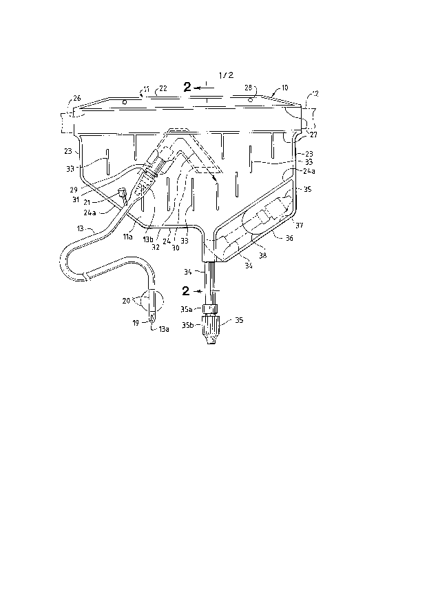
Referring to the drawings, the numeral 10 generally
designates a urine collection device comprising an abdominal bag
11, a belt 12 for supporting the bag about a wearer's waist, and
a catheter 13 for conveying urine from the bladder to the
collection bag. Figure 4 illustrates the device as it would be
worn by a male patient with catheter 13 extending through the
urethra and the distal end 13a of the catheter being disposed
within bladder 15. Urine drains into the bladder from kidneys
16 and ureters 17. The urethral sphincter located at 18 would
normally control flow from the bladder 15; however, the
sphincter is rendered inoperative or ineffective by catheter 13,
with the result that urine is free to flow from the bladder into
the catheter. Catheter 13 is a conventional retention catheter,
commonly called a Foley catheter, having an inlet 19 at its
distal end 13a. An inflatable balloon 20 is disposed near the
tip of the catheter and may be inflated into the expanded
condition depicted in broken lines in Figures 1 and 4 to provide
retention means for retaining the distal tip of the catheter
within the neck of the bladder. A stem 21 providing a suitable
self-sealing inflation port is located at the proximal end 13b
of the catheter. Inflation and deflation of the balloon is
achieved by inserting a needle of a syringe into the inflation
port, all as well known in the art.
Bag 11 is flat when empty and is dimensioned to extend over
a patient's abdomen or belly as shown in Figure 4.
Specifically, the bag has front and rear panels or walls lla and
llb, respectively joined together along their top side and
2l626l9
bottom edges 22-24. Top edge 22 is generally straight and
extends horizontally when the bag is worn.
In the embodiment shown in FIGS. 1-4, a horizontally-
elongated tubular channel 26 extends below top edge 22 and is
defined by parallel heat seal lines 27. Channel 26 serves as a
horizontally-elongated belt loop for receiving belt 12 and
thereby supporting or suspending the bag from a patient's waist.
That construction is advantageous because bag 11 is a disposable
item formed of a suitable thermoplastic material such as, for
example, a polyolefin film (e.g., polyethylene) laminated with
an appropriate barrier material (e.g., polyvinylidene chloride),
whereas the belt would ordinarily be formed of cloth and would
be reusable. The belt may be formed of cotton or any other soft
breathable fabric and equipped with a conventional clasp or
buckle (not shown) allowing ad~ustment of the size of the belt
so that it extends snugly but comfortably about a wearer's
waist.
In an alternate embodiment shown on Fig. 5, the means for
supporting the bag take the form of first and second belt
portions 12A' and 12B' which are respectively attached to the
side edges 23 of the bag. The belt portions 12A' and 12B' are
respectively provided along their distal ends with patches 39
and 40 of hook and loop fabric, such as commonly sold under the
designation VELCRO. Belt portions 12A' and 12B' may be attached
to the side edges of the bag by stitches 41 or any other
suitable means. Attaching the belt portions to the side edges
of the bag is advantageous in that a portion of the urine-
receiving chamber extends between the belt portions, thereby
21 6~61 9
providing a larger chamber than the embodiment shown on Fig. 1
in which tubular channel 26 reduces the volume of the bag. In
one embodiment, attaching the belt portions to the side edges of
the bag increased the bag's volume by about 30%. While belt
portions 12A' and 12B' may be connected to conventional clasp or
buckle components (not shown), it is believed that the use of
hook and loop fabric patches 39 and 40 is advantageous for
maintaining a low profile under a wearer's clothing and
increasing wearer comfort.
If desired, the upper edge portion of the bag 11 may be
provided with openings 28 that may be used to secure the upper
edge of the bag to the patient's undergarments by means of
safety pins or other suitable fasteners.
The dimensions of the bag may be varied depending on the
size of the patient. In general, the bag should have a width
within the range of about 20 to 40 centimeters (preferably about
30 centimeters) and a height of about 10 to 20 centimeters
(preferably about 15 centimeters). In any event, the bag should
be dimensioned to extend generally over the wearer's abdomen,
from his (her) waist down to the pelvic region, as depicted in
Figure 4. When the bag is so worn, it is positioned at
approximately the same height as the wearer's bladder 15.
An inlet tube 29 formed of polyvinyl chloride or other
suitable thermoplastic material is heat sealed to the upper
front wall lla of the bag and communicates in the interior of
the bag to a suitable one-way valve 30. As shown in the
drawings, the exterior portion of the inlet tube is operatively
connected to the proximal end 13b of catheter 13. The
--6--
2l626l9
connection might be a permanent one, although a separable
connection is preferred. To facilitate coupling and uncoupling
of the catheter and tube and at the same time achieve a secure
connection that will not become accidentally disrupted, it has
been found desirable to seal a connecting sleeve or nipple 31 to
the outer end of the inlet tube, the nipple being stepped as
shown (Figure 1) and being formed of a relatively rigid material
such as, for example, polystyrene.
The one-way valve 30 may be formed of a pair of inverted
V-shaped flexible thermoplastic strips 3Oa and 3Ob heat sealed
along their inner and outer edges to define a passage
communicating at one end with inlet tube 29 and open at its
other end only when fluid pressure within the passage forces the
strips 30a and 30b apart at that other end. The anti-refluxing
flap valve 30 is centrally positioned within the upper portion
of the bag about equal distances from side edges 23 and may be
advantageously secured in place by the lower heat seal line 27
that also defines the upper limits of the bag's interior and the
lower limits of the belt-receiving channel 26. It will be
understood that the same heat seal area that secures inlet tube
29 to the bag, with the inlet tube communicating with the
passage of flap valve 30, also seals off the leg of the valve
passage immediately adjacent tube 29, with the result that fluid
may flow through the valve passage only in the direction
indicated generally by arrow 32 in Figure 1.
As shown most clearly in Figure 3, the side walls lla and
llb of the bag are heat sealed to each other at a multiplicity
of attachment zones 33 spaced throughout the fluid-receiving
21 6261 9
body portion of the bag. The heat seals 33 are vertically
elongated and, in the illustration given, are generally parallel
with side edges 23. The length of each heat seal 33 is
substantially less than the maximum vertical dimension of the
fluid-receiving chamber and are laterally (horizontally) spaced
apart in vertically- staggered or offset relation. It is
important that a plurality of such heat seals 33 be provided,
although the particular number (10) shown in the drawings is not
critical and a somewhat greater or smaller number may be
provided as desired. Such heat seals are positioned and
arranged so that fluid within the bag cannot flow from one side
edge 23 to the other without encountering and being deflected by
one or more seals. The heat seals 33 therefore function as
flow-deflecting baffles, and the provision of multiple baffles
disperses flow and retards the rate of flow to eliminate or
greatly reduce the sloshing of fluid, and the sounds associated
with it, as a patient moves about. In addition, the multiple
heat seals 33 limit the extent of outward bulging of the side
walls of the bag as it is filled and promote more uniform
distribution of liquid throughout the width and height of the
bag, thereby insuring that the bag maintains a relatively flat
and inconspicuous profile even when it is filled.
A short drain tube 34 formed of polyvinyl chloride or other
flexible thermoplastic material is heat sealed to the lower
edges of the bag and communicates with the bag as most clearly
shown in Figures 1 and 2. At its free end, the drain tube is
equipped with a suitable valve 35. The particular valve
depicted in the drawings is composed of two elements 35a and 35b
21 6261 9
that are threadedly connected to each other; opening and closing
of the valve is achieved simply by rotating element 35b one way
or the other with respect to element 35a. Since such a valve is
entirely conventional and well known for use in collection
appliances, a more detailed discussion of its structure and
operation is believed unnecessary.
Portions 24a of the bag's lower edge 24 slope downwardly
and inwardly to direct fluid towards the centrally-disposed
drain tube 34, as depicted in Figure 1. In the embodiment
illustrated, one lower side portion of the bag extends
downwardly and is heat sealed along lower edge 36 to define a
pocket 37. Slit 38 forms the entrance to that pocket. The
drain tube 34 and valve 35 may be inserted into the pocket, as
shown in Figure 4 and in broken lines in Figure 1, to restrain
movement of the drain tube during normal wearing of the bag.
When draining of the contents of the bag is desired, the tube is
simply removed from the pocket and valve 35 is manipulated into
open condition. For reasons already given, such a procedure is
far more convenient for the patient than those involved in the
draining of a conventional leg bag.
While the urinary collection appliance is shown as it would
be worn by a male patient, it is to be understood that the
appliance is equally useful for female patients. In both cases,
the intrinsic bladder detrusor muscle tone and the
intraperitoneal pressure created during normal body movements or
actions, such as breathing, walking, and bending, provide
sufficient pressure to direct urine upwardly through the short
length of catheter 13 and into the inlet tube 29 and one-way
2162619
valve 30 in the upper central portion of the collection bag.
Therefore, despite the fact that the urine collection bag is
carried by a belt or waistband over the patient's abdomen, urine
from the bladder is readily directed into the bag. Reverse
flow, especially as might otherwise occur if the patient were
sitting or reclining, is prevented by the anti-refluxing flap
valve 30.
While in the foregoing, an embodiment of the invention has
been described in detail for purposes of illustration, it will
be understood by those skilled in the art that many of these
details may be varied without departing from the spirit and
scope of the invention.
--10--