Sélection de la langue

Search

Sommaire du brevet 2163106 

Énoncé de désistement de responsabilité concernant l'information provenant de tiers

Une partie des informations de ce site Web a été fournie par des sources externes. Le gouvernement du Canada n'assume aucune responsabilité concernant la précision, l'actualité ou la fiabilité des informations fournies par les sources externes. Les utilisateurs qui désirent employer cette information devraient consulter directement la source des informations. Le contenu fourni par les sources externes n'est pas assujetti aux exigences sur les langues officielles, la protection des renseignements personnels et l'accessibilité.

Disponibilité de l'Abrégé et des Revendications

L'apparition de différences dans le texte et l'image des Revendications et de l'Abrégé dépend du moment auquel le document est publié. Les textes des Revendications et de l'Abrégé sont affichés :

  • lorsque la demande peut être examinée par le public;
  • lorsque le brevet est émis (délivrance).
(12) Demande de brevet: (11) CA 2163106
(54) Titre français: ROBINET DE SOUTIRAGE POUR CONTENANTS OU TONNEAUX DE BOISSON
(54) Titre anglais: TAP HEAD FOR BEVERAGE CONTAINERS OR VESSELS
Statut: Réputée abandonnée et au-delà du délai pour le rétablissement - en attente de la réponse à l’avis de communication rejetée
Données bibliographiques
(51) Classification internationale des brevets (CIB):
  • B67D 01/14 (2006.01)
  • B67D 01/08 (2006.01)
(72) Inventeurs :
  • DEGENKOLBE, HORST (Allemagne)
  • OBIER, DETLEF (Allemagne)
(73) Titulaires :
  • D.S.I. JOSEF BREITWISCH & CO GMBH
(71) Demandeurs :
  • D.S.I. JOSEF BREITWISCH & CO GMBH (Allemagne)
(74) Agent: SWABEY OGILVY RENAULT
(74) Co-agent:
(45) Délivré:
(86) Date de dépôt PCT: 1994-05-06
(87) Mise à la disponibilité du public: 1994-11-24
Requête d'examen: 1999-02-26
Licence disponible: S.O.
Cédé au domaine public: S.O.
(25) Langue des documents déposés: Anglais

Traité de coopération en matière de brevets (PCT): Oui
(86) Numéro de la demande PCT: PCT/EP1994/001477
(87) Numéro de publication internationale PCT: EP1994001477
(85) Entrée nationale: 1995-11-16

(30) Données de priorité de la demande:
Numéro de la demande Pays / territoire Date
P 43 16 457.9 (Allemagne) 1993-05-17

Abrégés

Abrégé anglais


Tap heads for beverage containers or barrels respectively
comprise a plunger able to be actuated by a hand lever, a
beverage connection, a connection for a gaseous pressure medium
and a container connection. In previous tap heads, the problem
exists that a high gas pressure is maintained in the interior of
the tap head, when the tap head is closed. Due to this the
housing gasket of the tap head is pressed against the flange of
the fitting, so that the tap head can only be released from the
flange with a considerable application of force.
In order to provide a tap head, which makes it possible to
respectively remove the gas pressure without risk in the interior
of the tap head, it is proposed that a relief valve is connected
to the interior of the tap head.

Revendications

Note : Les revendications sont présentées dans la langue officielle dans laquelle elles ont été soumises.


Claims
1. Tap head (1) for beverage containers or barrels, with a
tap head plunger (6) able to be actuated by a hand lever (4), a
beverage connection (3), a connection (2) for a gaseous pressure
medium (CO2) and a container connection (8), a relief valve (9)
being connected to the interior (16) of the tap head,
characterised in that the tap head plunger (6) is provided with
a flange (14) and that the relief valve (9) is constructed and
arranged so that when the hand lever (4) is raised, the relief
valve (9) is opened forcibly by way of the tap head plunger (6)
moving upwards due to this, by its flange (14).
2. Tap head according to Claim 1, characterised in that the
relief valve (9) comprises a valve housing (26), which is
fastened laterally to the tap head housing wall (10), a valve
plunger (17) with a flange (19), a compression spring (20)
inserted between the flange (19) and an adjustable screw (22),
a gasket ring (18) and a triangular projection (21).
3. Tap head according to Claim 1 or 2, characterised in that
the flange (14) provided on the tap head plunger (6) comprises
openings (15) for the passage of gas.

Description

Note : Les descriptions sont présentées dans la langue officielle dans laquelle elles ont été soumises.

2163I 06
The invention relates to a tap head for beverage containers or
barrels, with a tap head plunger able to be actuated by a hand
lever, a beverage connection, a connection for a gaseous pressure
medium and a container connection, a relief valve being connected
to the interior of the tap head.
Tap heads of this type serve in known manner for the removal of
beverages from beverage containers or beverage barrels, such as
beer barrels. For this purpose, the tap head with the said
connections is connected to the flange of a fitting with the hand
lever raised. The fitting represents the container connection
located in a container opening, which is equipped with a
particular, known valve. By pulling down the hand lever of the
tap head and thus by actuating the tap head plunger, a plunger
flange located on this plunger is pressed against a housing
gasket and simultaneously the valve of the fitting is opened, so
that a gas-tight connection is guaranteed. Pressurised gas flows
through the interior around the tap head plunger into the
container and conveys the beverage through a central pipe to the
beverage connection and from there by way of a line to the actual
bar dispenser.
After emptying the container, the hand lever of the tap head is
tilted upwards, so that the compression of the housing gasket is
discontinued and the fitting in the housing-barrel is again
closed.
One considerable problem consists in that particularly at a
higher working pressure in the interior of the tap head,
particularly i,n the lower cavity around the tap head plunger, a
gas pressure is maintained which may reach up to approximately
6 bars. Due to this the housing gasket of the tap head is
pressed against the flange of the fitting. The drawback consists
in that the tap head can only be released from the flange by
overcoming the adhesion produced by the gas pressure, which

216~106
signifies not solely a considerable application of force, but
also a certain danger for the operator.
The problem mentioned previously can be obviated at least
partially in a tap head mentioned at the beginning, which is
known from the document EP-A-0 432 650. The pressure relief
valve is however in this case arranged pointing approximately
radially outwards on the tap head housing, so that in its
direction of movement, the valve plunger located in the valve
housing extends substantially at right angles to the direction
of movement of the tap head plunger. The pressure relief valve
serves for the ventilation of the storage container and must be
actuated in each case manually, for example by means of a hand
lever. If the storage container is to be ventilated, the keg
fitting must be opened. It is moreover also conceivable, in the
closed state, by manually actuating the pressure relief valve,
to ventilate solely the interior of the tap head housing.
It is accordingly the object of the invention, whilst preserving
the advantages of the arrangement of a pressure relief valve
assumed to be in accordance with the known type, to provide a tap
head, in which, automatically after each closure process, a
relief of the pressure takes place in the interior of the tap
head, without requiring any additional manual actuations.
Based on the tap head mentioned at the beginning, the object set
is achieved according to the invention due to the fact that the
tap head plunger is provided with a flange and that the relief
valve is constructed and arranged so that when the hand lever is
raised, the relief valve is opened forcibly by way of the tap
head plunger moving upwards due to this, by its flange.
Advantageous embodiments of the tap head will become apparent
from the Sub-claims.

21 631 06
The drawings show one embodiment of the invention
diagrammatically and in which:
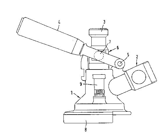
Figure 1 is a side view of a tap head,
Figure 2 is a vertical section through the tap head according to
Figure 1, the relief valve being shown tilted through 90 about
the central axis in the plane of the drawing, the tap head
plunger being located in the uppermost position and
Figure 3 is a vertical section according to Figure 2, the tap
head plunger being located in a central vertical position.
Figure 1 is a side view of a tap head 1 with a connection Z for
a gaseous pressure medium, for which carbon dioxide (CO2) is
normally used. Furthermore, the tap head comprises a beverage
connection 3 as well as a ~ ; n 3 ~ L ~ne~ n
"/

,~ 21631o6
to the fitting seated in the container opening and which is not
shown. The tap head also comprises a hand lever 4 for actuating
the tap head plunger 6. The hand lever is mounted in the swivel
bearing 5 and comprises pivots 7 known per se, on both sides of
the tap head plunger. Figure 1 also shows a relief valve 9 in
the correct lateral position, namely at an angle of 90 with
respect to the pressure medium connection 2.
As can be seen from Figures 2 and 3, the relief valve 9 comprises
a valve housing 26, which is attached laterally to the tap head
housing wall 10. Able to slide vertically in the valve housing
26 is a valve plunger 17 together with a flange 19 seated thereon
and with a lower projection 21. Inserted between the flange 19
and an adjustable screw 22 is a compression spring 20, which
normally ensures that the flange 19 presses against a gasket ring
18 loca-ted below the flange, which gasket ring 18 in turn seals
an opening in the tap head housing wall 10, and indeed in the
region of the projection 21. The adjustability of the screw 22
able to be scre~ed in the internal screw thread 23 of the valve
housing 26 is arranged so that the spring pressure can be
adjusted or regulated in accordance with the situation.
Two gasket rings 11 and 12, in practice so-called O-rings, are
provided between the tap head plunger 6 and the tap head housing
wall 10. Furthermore, a further gasket ring 13 is inserted in
the lower part of the tap head. A flange 14 provided with
openings 15 for the passage of gas is located, preferably screwed
to the lower part of the tap head plunger. In the region of the
tap head housing wall 10, the tap head plunger 6 comprises
recesses 25 in the region between the two sealing rings 11 and
12, which recesses allow the passage of gas downwards, in the
lowermost position of the tap head plunger. The reference
numeral 16 designates the interior of the tap head, to which the
relief valve 9 is connected. The efficiency of the relief valve
is further increased due to the fact that the lower projection
21 has an approximately triangular or star-shaped cross-section.

21 63I 0~
..
The method of operation is essentially as follows.
When the hand lever 4 is swung upwards, the tap head plunger 6
is brought into the uppermost position according to Figure 2.
In this case the relief valve 9 is automatically actuated and
indeed due to the fact that the flange 14 presses against the
lower end of the projection Zl, so that with this the relief
valve is opened and the gas pressure is able to escape from the
tap head interior 16 through the spaces into the projection 21
and through the resulting gas outlet gap 24 on the under side of
the gasket ring 18 towards the outside.
Figure 3 shows a central vertical position of the tap head
plunger 6. In a lower position which is not shown, in which the
aforedescribed opening of the container takes place, the flange
14 presses against the gasket ring 13. In one of the said
central positions and in the lowermost position of the tap
plunger 6, the relief valve 9 is permanently closed due to the
pressure of the compression spring 20. However, the
automatically acting relief valve 9 also fulfils a safety
function, namely if an inadmissibly high excess pressure prevails
in the beverage container or in the compressed gas supply~ The
compression spring 20 may be adjusted by means of the screw 2Z,
which above all is fixed in practice, so that the relief valve
opens automatically at the time of such an inadmissibly high
pressure.

Dessin représentatif
Une figure unique qui représente un dessin illustrant l'invention.
États administratifs

2024-08-01 : Dans le cadre de la transition vers les Brevets de nouvelle génération (BNG), la base de données sur les brevets canadiens (BDBC) contient désormais un Historique d'événement plus détaillé, qui reproduit le Journal des événements de notre nouvelle solution interne.

Veuillez noter que les événements débutant par « Inactive : » se réfèrent à des événements qui ne sont plus utilisés dans notre nouvelle solution interne.

Pour une meilleure compréhension de l'état de la demande ou brevet qui figure sur cette page, la rubrique Mise en garde , et les descriptions de Brevet , Historique d'événement , Taxes périodiques et Historique des paiements devraient être consultées.

Historique d'événement

Description Date
Demande non rétablie avant l'échéance 2002-05-06
Le délai pour l'annulation est expiré 2002-05-06
Réputée abandonnée - omission de répondre à un avis sur les taxes pour le maintien en état 2001-05-07
Inactive : Dem. traitée sur TS dès date d'ent. journal 1999-03-18
Inactive : Renseign. sur l'état - Complets dès date d'ent. journ. 1999-03-18
Inactive : Acc. réc. RE - Pas de dem. doc. d'antériorité 1999-03-18
Toutes les exigences pour l'examen - jugée conforme 1999-02-26
Exigences pour une requête d'examen - jugée conforme 1999-02-26
Inactive : Demande ad hoc documentée 1997-05-06
Réputée abandonnée - omission de répondre à un avis sur les taxes pour le maintien en état 1997-05-06
Demande publiée (accessible au public) 1994-11-24

Historique d'abandonnement

Date d'abandonnement Raison Date de rétablissement
2001-05-07
1997-05-06

Taxes périodiques

Le dernier paiement a été reçu le 2000-04-13

Avis : Si le paiement en totalité n'a pas été reçu au plus tard à la date indiquée, une taxe supplémentaire peut être imposée, soit une des taxes suivantes :

  • taxe de rétablissement ;
  • taxe pour paiement en souffrance ; ou
  • taxe additionnelle pour le renversement d'une péremption réputée.

Les taxes sur les brevets sont ajustées au 1er janvier de chaque année. Les montants ci-dessus sont les montants actuels s'ils sont reçus au plus tard le 31 décembre de l'année en cours.
Veuillez vous référer à la page web des taxes sur les brevets de l'OPIC pour voir tous les montants actuels des taxes.

Historique des taxes

Type de taxes Anniversaire Échéance Date payée
TM (demande, 4e anniv.) - petite 04 1998-05-06 1998-05-04
Requête d'examen - petite 1999-02-26
TM (demande, 5e anniv.) - petite 05 1999-05-06 1999-05-05
TM (demande, 6e anniv.) - petite 06 2000-05-08 2000-04-13
Titulaires au dossier

Les titulaires actuels et antérieures au dossier sont affichés en ordre alphabétique.

Titulaires actuels au dossier
D.S.I. JOSEF BREITWISCH & CO GMBH
Titulaires antérieures au dossier
DETLEF OBIER
HORST DEGENKOLBE
Les propriétaires antérieurs qui ne figurent pas dans la liste des « Propriétaires au dossier » apparaîtront dans d'autres documents au dossier.
Documents

Pour visionner les fichiers sélectionnés, entrer le code reCAPTCHA :


Pour visualiser une image, cliquer sur un lien dans la colonne description du document. Pour télécharger l'image (les images), cliquer l'une ou plusieurs cases à cocher dans la première colonne et ensuite cliquer sur le bouton "Télécharger sélection en format PDF (archive Zip)" ou le bouton "Télécharger sélection (en un fichier PDF fusionné)".

Liste des documents de brevet publiés et non publiés sur la BDBC .

Si vous avez des difficultés à accéder au contenu, veuillez communiquer avec le Centre de services à la clientèle au 1-866-997-1936, ou envoyer un courriel au Centre de service à la clientèle de l'OPIC.


Description du
Document 
Date
(aaaa-mm-jj) 
Nombre de pages   Taille de l'image (Ko) 
Abrégé 1994-11-23 1 22
Description 1994-11-23 5 202
Revendications 1994-11-23 1 28
Dessins 1994-11-23 3 77
Dessin représentatif 1999-06-01 1 10
Accusé de réception de la requête d'examen 1999-03-17 1 173
Courtoisie - Lettre d'abandon (taxe de maintien en état) 2001-06-03 1 182
Rapport d'examen préliminaire international 1995-11-15 17 581
Taxes 1997-04-22 1 59
Taxes 1995-11-15 1 45