Note : Les descriptions sont présentées dans la langue officielle dans laquelle elles ont été soumises.
2163684
SUCCESSIVE GAS AND WATER DISPLACEMENT PROCESS
FIELD OF THE INVENTION
The present invention relates to the field of oil recovery and, in particular,
to a
process for increasing the efficiency of a gas displacement process for the
recovery of
crude oil from a natural reservoir.
BACKGROUND OF THE INVENTION
A number of known processes for enhancing recovery of crude oil from oil-
bearing subterranean formations involve flooding the reservoir with gas to
displace oil
to a producing well in communication with the reservoir. In an effort to
improve the
recovery of this valuable resource, attention has turned to increasing the
efficiency of
such oil production processes. Such processes are typically referred to as
enhanced oil
recovery (EOR) processes.
One EOR process is a water alternating gas (WAG) process described in United
States Patent No. 3,244,228 (David R. Parrish; April 5, 1966). The WAG process
involves injecting a water- and oil-immiscible gas into a previously water-
flooded
reservoir, injecting water into the reservoir, recovering oil from a producing
well that
communicates with the reservoir, and repeating the cycle. The gas injection
step is
carried out over a period of several days to several months or a year until a
gas
saturation of about 5% pore volume is established and gas breakthrough is
observed in
the producing well. The water injection step is then carried out until a water
1
216~~84
saturation of from 5 to 10% pore volume is established and water breakthrough
into
the producing well is observed. Both the gas injection and water injection
steps are
repeated cyclically one or more times.
The WAG process is typically applied horizontally to recover oil from water-
wet homogeneous sandstone reservoirs. In a water-wet sandstone reservoir, oil
tends
to occupy pore spaces as a non-wetting phase. Gas is also non-wetting so that
free gas
tends to displace residual oil from larger pores into mobile channels occupied
by water
(Champion, J.H. and Shelden, J.B. "An immiscible WAG injection project in the
Kuparuk River Unit" J Petrol Tech 533-540; May, 1989). Studies show that the
immiscible WAG process may result in the recovery of an additional 1-3% of the
original-oil-in-place (OOIP) (Ma, T.D. and Youngren, G.K. "Performance of
immiscible water-alternating-gas (IWAG) injection at Kuparuk River Unit, North
Slope, Alaska" Paper SPE 28602 presented at the SPE 69th Annual Technical
Conference and Exhibition, New Orleans, LA, USA; September 25-28, 1994).
Another EOR process is described in United States Patent No. 3,500,914
(Petteway, J.C.; March 17, 1970) which relates to a method for improving the
efficiency of a water-flooding process for oil recovery from oil-bearing
anticlines by
first sweeping the oil pool with a gas. The Petteway process aims to improve
oil
recovery from a reservoir having an unusually low recovery efficiency from a
natural
water drive; the residual oil content is typically 45% OOIP following the
water-
flooding phase. The patent teaches decreasing the residual oil content by an
amount
approximately equal to the free gas content remaining in the reservoir after
water
influx and that a maximum residual gas content of 20% can be expected.
Consequently, using the Petteway process, the lowest achievable residual oil
content
would be about 25% OOIP. The process relies upon the presence of an underlying
aquifer and a natural water drive. Petteway suggests, by the behaviour of
reservoir
described in the patent, that his process is applicable to water-wet
reservoirs, similar to
the immiscible WAG process described above. Such water-wet reservoirs have
high
connate water saturations of about 30%. A discussion of expected results for
oil
2
2163684
recovery with these reservoir characteristics follows in the detailed
description of the
present invention.
Petteway teaches that his process is applicable to those "reservoirs having a
low
recovery efficiency as a result of irregular, 'dead-end' pore spaces", which
"pore
spaces trap oil during influx of a natural water drive". Thus, the Petteway
patent is
specifically directed to improving processes having a low volumetric sweep
efficiency
wherein there are significant unswept regions in the reservoir, as opposed to
microscopically trapped residual oil which remains in a water-swept region of
the
reservoir. Accordingly, Petteway's patent would suggest to a person skilled in
the art
that his process is applicable to reservoirs having a high residual oil
content of at least
about 45% OOIP. One skilled in the art would not be inclined nor does Petteway
suggest that his process could be used to improve an already efficient gas
flood
process by conducting a water flood, since water floods are typically more
inefficient
than gas floods. Petteway's teachings or disclosed process would not,
therefore,
suggest to a person skilled in the art that a gas displacement process having
a high
sweep efficiency and the capability to reduce the residual oil content of a
reservoir to
about 20 to 25% OOIP could be improved by using a water flood.
Another EOR process is a so-called double displacement process wherein oil is
first produced as a result of a vertical water flood and subsequently followed
by gas
injection to drain oil from the pores by gravity (Langenberg, M.A. et al
"Performance
and expansion plans for the double displacement process in the Hawkins Field
Unit"
Paper SPE 28603 presented at the SPE 69th Annual Technical Conference and
Exhibition, New Orleans, LA, USA; September 25-28, 1994). This process teaches
that an increased recovery will be obtained from gas displacement rather than
water
displacement. A person skilled in the art would be led to conclude that the
gas
displacement step is more effective than the water displacement step and that
there is
no remaining recoverable oil after gas displacement.
The present invention is directed to improving the efficiency of oil recovery
from non-water-wet carbonate reservoirs which are common in the Western Canada
3
2163684
Basin. The process of the present invention is particularly applicable to
carbonate
reservoirs having a connate water saturation of about 15% pore volume or less,
as
opposed to a connate water saturation of about 30% for homogenous sandstone
reservoirs.
A conventional process for recovery of oil from such a carbonate reservoir is
a
vertical gas displacement process to expand and/or form a gas cap above the
oil pool
and to displace oil into a producing well. Oil is produced from the producing
well
withdrawing from the oil zone until the gas/oil interface is lowered to a
point at which
excessive gas production and/or water production from an underlying aquifer
due to
coning terminates economic production. Diligent operation of a conventional
gas
displacement process typically provides a sweep efficiency of about 90% or
greater.
The residual oil content after a high sweep efficiency gas displacement is
typically
about 20-25% OOIP. The residual oil following a high sweep efficiency gas
displacement process is not found in unswept or bypassed regions in the
formation but
rather, the residual oil is found to be widely distributed on a microscopic
level. Thus,
persons skilled in the art have typically concluded that this microscopically
trapped
residual oil is not recoverable with any economically feasible immiscible
process and,
due to the high cost of possible miscible processes, oil recovery has
typically been
terminated at this point.
This conventional thinking of persons skilled in the art is exemplified in the
operation of the Leduc D3-A reservoir in Alberta, Canada. Oil was produced
from the
reservoir by a gas displacement process for about 40 years. Finally, in 1989,
oil
production was determined to be no longer economically feasible. Accordingly,
Imperial Oil made the decision to terminate oil production with a residual oil
content
of about 25% and to begin gas production by blowdown from the reservoir. This
decision was widely heralded as the end of an era and it is clear that persons
skilled in
the art believed that no further oil was economically recoverable from the
reservoir by
any known immiscible process (Energy Resources Conservation Board Decision D
84-
2).
4
2163684
While a residual oil content of about 20-25% OOIP is widely accepted as not
economically recoverable, it will be appreciated by those skilled in the art
that a
residual oil content of from 20 to 25% represents a significant volume of oil
which
remains in the reservoir after a conventional gas displacement process has
been
completed. However, known processes such as a miscible gas flood are not
always
economic. It is clearly desirable that a more economical and more efficient
method
for recovering at least a portion of the remaining oil be found.
It is an object of the present invention to provide a method for increasing
oil
recovery from carbonate reservoirs having a low connate water saturation.
SUMMARY OF THE INVENTION
According to one aspect of the present invention, there is provided a process
for recovering at least a portion of residual oil from an oil-bearing
heterogeneous
carbonate reservoir having a connate water saturation of less than about 15%
pore
volume from which oil has been recovered by gas displacement resulting in a
residual
oil content of less than about 25% pore volume and a gas saturation of from
about 60
to 80% pore volume in a gas-displaced region of the reservoir, comprising the
steps of
displacing a portion of the residual oil in the gas-displaced region of the
reservoir with
water to mobilize oil and to drive the mobilized oil upwardly in the reservoir
to
accumulate, thereby providing a region of a higher oil content in the
reservoir, and
producing oil from a producing well withdrawing from the region of higher oil
content.
According to another aspect of the present invention, there is provided a
successive gas and water displacement process for improving the recovery of
oil from
an oil-bearing heterogeneous carbonate reservoir having a connate water
saturation of
less than about 15% pore volume, comprising the steps of vertically displacing
oil by
gas displacement of oil from an oil zone in the reservoir to a producing well
and
producing oil from the well; periodically measuring the position of a gas/oil
interface
5
2163684
relative to sea level and determining a residual oil content and a gas
saturation of a
pore volume of a gas-displaced region of the reservoir based on the
measurements and
a material balance; continuing gas displacement and oil production such that
the
residual oil content in the gas-displaced region of the reservoir is less than
about 25%
pore volume and the gas saturation is in the range of from about 60 to 80%
pore
volume; suspending oil production and terminating gas displacement when oil
has been
displaced from a significant portion of the oil zone; displacing oil from the
gas-
displaced region of the reservoir with water to mobilize oil and to drive the
mobilized
oil upwardly in the reservoir to accumulate, thereby providing a region of a
higher oil
content in the reservoir; and recommencing the production of oil from the
region of
higher oil content.
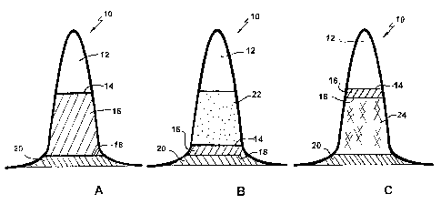
BRIEF DESCRIPTION OF THE DRAWINGS
In drawings which illustrate embodiments of the present invention,
Figure 1A is a depiction of the relative positions of a gas cap, an oil zone
and
an aquifer in a carbonate reservoir;
Figure 1 B is a depiction of the reservoir of Figure 1A following a gas
displacement step;
Figure 1C is a depiction of the reservoir of Figure 1B following a water
displacement step;
Figure 2 is a graphical representation of Leduc D3-A trapped gas saturation
data; and
Figure 3 is a graphical representation of three-phase residual oil content
data.
DETAILED DESCRIPTION OF PREFERRED EMBODIMENTS
In accordance with the present invention, oil is recovered from a vugular
carbonate reservoir by a successive gas and water displacement process. A
major
6
CA 02163684 1996-11-19
portion of the original oil in place (OOIP) is recovered by a conventional
process of
gas displacement. With a high sweep efficiency in the gas displacement step,
the
residual oil content in the gas-displaced portion of the reservoir is from
about 20 to
25% pore volume. At this point, the gas saturation in the gas-displaced region
of the
reservoir is in the range of from about 60 to 80% pore volume. According to
the
present invention, the gas displacement step is followed by a water
displacement step
to recover residual oil from the reservoir. The water displacement step of the
successive gas and water displacement process of the present invention enables
a
further oil recovery of up to about 5 to 15% of the OOIP.
The successive gas and water displacement process of the present invention is
particularly applicable to non-water-wet heterogeneous oil-bearing carbonate
reservoirs
having a connate water saturation (SH,,,) of approximately 15% pore volume or
less, as
opposed to an S,,,,, value of about 30% pore volume for water-wet sandstone
reservoirs.
Target carbonate reservoirs are common in the Western Canada Basin. It is
important
to the process of the present invention that the reservoir have a low connate
water
saturation of approximately 15% pore volume or less and a. relatively high gas
saturation of from about 60 to 80% pore volume following a gas displacement
step.
Referring to Figure 1 A, a typical carbonate reservoir 10 has a gas cap 12, a
gas/oil interface 14, an oil zone 16, an oil/water interface 18 and an
underlying aquifer
20. The reservoir depicted in Figure 1 A is typical of a reefal-type
reservoir. The
reservoir may also be a sloped reservoir which is capped by a fault, for
example.
While Figure lA shows an underlying aquifer, it is not necessary to the
present
invention that the reservoir have an underlying aquifer. It is also not
necessary that
the reservoir have a gas cap as shown in Figure 1 A. A gas cap may be formed
above
the oil pool during the gas displacement step.
The oil reservoir may have been immiscibly flooded with gas in a previous
displacement process, for example in a vertical gas displacement or double
displacement process as described above, or a gas displacement step may be
used to
initiate the successive gas and water displacement process of the present
invention.
7
2163684
The gas displacement step is applied vertically, for example by gas injection
and/or oil production to form and/or expand the gas cap 12 into the oil zone
16 in the
reservoir 10. Suitable gases for gas injection include hydrocarbon gases, for
example
solution gases stripped from oil produced on site, carbon dioxide, nitrogen
and/or flue
gas. Gas could also be evolved from the oil as reservoir pressure decreases.
Oil is
produced from a producing well (not shown) from the oil zone 16, for example
near
the oil/water interface 18. Gas may be injected to sustain gas cap expansion
during oil
production. If there is an underlying aquifer, the oil/water interface 18 is
preferably
maintained at substantially the same level in the reservoir 10 during the gas
injection
step.
Periodic measurement during the gas displacement step to determine a
requirement for adjusting the well production and/or injection rates ensures
that the
gas/oil interface 14 moves uniformly downwardly in the reservoir to maximize
the
sweep efficiency and to minimize the chances of bypassing regions of the
reservoir.
Oil production by gas displacement may be conducted as long as economic
production of oil is possible. For example, when excessive water production
from the
underlying aquifer 20, if present, occurs for example as a result of coning,
or excess
gas production occurs, gas injection and oil production are terminated. The
relative
positions of the gas/oil and oil/water, if present, interfaces at this point
are depicted in
Figure 1B. The depths of the gas/oil and oil/water, if present, interfaces,
located using
a logging device, such as a gradiomanometer which measures fluid density, are
used to
determine the residual oil content and the gas saturation, in a manner known
to those
skilled in the art, by material balance in view of the reservoir porosity and
structural
characteristics and the connate water saturation in the oil zone.
Following diligent operations during gas cap expansion and downward
displacement of oil by gas to provide a high sweep efficiency, for example of
90% or
higher, and to minimize the bypassing of regions of the reservoir, the
residual oil
content of the gas-displaced portion of the reservoir is very low in the range
of from
about 20 to 25% pore volume. Due to the low connate water saturation of the
target
8
2163684
reservoirs, the gas saturation is in the range of from about 60 to 80% pore
volume.
The level of residual oil saturation is dependent on the gas saturation which
in turn is
influenced by heterogeneities, system wettability, capillarity and production
practices.
A gas saturation in the range of from about 60 to 80% pore volume is
considered high
and this is characteristic of heterogenous carbonate reservoirs. Homogeneous
sandstone reservoirs do not typically have a high gas saturation and are
therefore not
target reservoirs for the process of the present invention.
The water displacement step is then conducted to move the oil upwardly in the
reservoir 10. Water displacement may be the result of natural aquifer response
to gas
cap production and/or water may be injected into the reservoir to drive the
oil/water
interface 18 upwardly, as shown in Figure 1 C. Even if an underlying aquifer
is
present, it may be desirable to maintain the reservoir pressure or to augment
the
natural water drive by water injection into the aquifer if the natural water
drive is or
becomes weak.
In the water-flooding step, two displacement fronts occur. An upper oil
displacement front is characterized by oil displacing the high gas saturation
region 22
(Figure 1B) resulting in a high trapped gas saturation. At this front, gas is
trapped in
the pores by oil and the trapped gas saturation is from about 40 to 55% pore
volume.
At the lower water displacement front, water displaces and mobilizes oil in
the
presence of the already trapped gas in a successively displaced zone 24, shown
in
Figure 1 C. Unlike the process described by Petteway in United States Patent
No.
3,500,914 wherein "the residual oil content is expected to decrease by an
amount
approximately equal to the free gas content remaining in the reservoir after
water
influx", oil production in the process of the present invention is dependent
on the
ability of water to displace oil in the presence of a high trapped gas
saturation. At
high trapped gas saturations, gas occupies from about 40 to 55% pore volume so
that
as the reservoir is subjected to a water flood, water displaces a significant
portion of
the gas-flood residual oil from the pores rather than further trapping it
therein.
9
2163684
In the successively displaced zone 24, the trapped gas saturation remains
substantially unchanged at about 40 to 55% pore volume and water displaces oil
to
increase the water saturation from the connate water saturation of about 15%
or less to
about 30 to 40% pore volume, to achieve a continuously connected water phase
and
render it mobile. Accordingly, oil is displaced from the gas-flood residual
oil
concentration of 20 to 25% pore volume to a final saturation of from about 5
to 15%
pore volume in the successively displaced zone 24.
The production of oil mobilized as a result of successive displacement can be
initiated once there is significant accumulation in the oil zone 16. Oil
production may
be completed in the vicinity of the original gas/oil interface 14 shown in
Figure 1 A.
In another embodiment, the water displacement and oil production steps may be
conducted concurrently. In this case, the producing well would be periodically
completed up-hole.
In a further embodiment, the water-flooding step and the second oil production
step are carried out cyclically by producing oil once the water drive has
produced an
oil zone 16 of sufficient thickness so that oil can be produced without
significant water
breakthrough from the underlying aquifer 20. Once the thickness of the oil
zone 16 is
again reduced to a thickness where water production cannot be tolerated or the
oil
zone 16 has moved upwardly in the reservoir 10, oil production is suspended
and oil
production is moved up-hole.
The residual oil saturation following the water displacement step, So,.,,,,
depends
on the presence and amount of other phases occupying the pore space. As
mentioned
previously herein, the connate water saturation of a carbonate reservoir is
less than
about 15%, typically from about 8 to 10%. Following gas displacement, the gas
saturation is considered to be high at from about 60% to 80% and the residual
oil
content is from about 20 to 25%. The high gas saturation characteristic of
heterogenous carbonate reservoirs is exploited by the process of the present
invention
to yield a further oil recovery of up to about 10 to 15% OOIP. In contrast, a
homogeneous sandstone reservoir with a high connate water saturation of 30%,
normal
21636 84
for a water-wet sandstone, and a residual oil content of 25% would have a gas
saturation of 45% following the gas injection step.
The dependency of the process of the present invention on a low connate water
saturation and a high gas saturation is illustrated in hypothetical cases in
Table I.
Table I is a comparison of the final residual oil content and the difference
between the
residual oil content after gas displacement and after water displacement for
reservoirs
having the ideal conditions of low connate water saturation and high gas
saturation
after gas displacement (Cases I and II) with reservoirs having low gas and
high
connate water saturations (Cases III and IV). The expected results are
expressed in
terms of percentage pore volume and the calculations are made assuming high
sweep
efficiencies. In Table I, S,,,, represents connate water saturation, S~
represents gas
saturation, So represents oil saturation, SW represents water saturation, Sgt
represents
trapped gas saturation, So,g represents residual oil content after gas
displacement, and
So,f represents final residual oil content.
Case I represents a non-water-wet heterogeneous carbonate reservoir which is a
target reservoir for the process of the present invention. In such target
reservoirs, a
typical connate water saturation is about 10% and the gas saturation following
the gas
displacement step is typically 70%. A high sweep efficiency gas displacement
step
results in a residual oil content of 20% (So,g). After the oil displacement
front of the
water displacement step, the water saturation equals the connate water
saturation, oil
displaces gas to a trapped gas saturation of 49% (see Figure 2) and the oil
saturation
increases to 41%. Following the water displacement front of the water
displacement
step, the trapped gas saturation remains at 49%, the water saturation
increases to 40%
displacing oil and reducing the residual oil content to 11% (So,f). The net
result is a
residual oil saturation of 11 %, representing an increased oil recovery of 9%
OOIP.
Table I illustrates, in Case II, the effect of a lower gas saturation at the
end of
the gas displacement step. In the oil displacement front of the water
displacement
step, the water saturation equals the connate water saturation (SWc=10%) and
oil
displaces gas to a trapped gas saturation of 41% and an oil saturation of 49%.
11
2163684
~ 3 0 '~ =~
o m cn o cn t
W J ~/j p o p p o c
~ v~ ~ p
v~
U M
tb o v
p O C/~ p p p
M ~ M
~ U
~ v~ ~ cd
M "C
a =~
o kn to kn m .~
C/~ o M =-= ~ -- cl~
Cd
~ 3 ~ ~ N t+r
y ~ O 3 O 3 O
~.,
C/1
o m ~
O
v
_ O
U a
m ,-= U
~,
-Ny
v~
W o p w
.!~
U
113 \ ~, o o~ ~ rn o
N1' V~ Itt cn
U O aS
rA
cn
an
C~
o CT
cd
C7 A A
)
2163684
Following the water displacement front of the water displacement step, the
trapped gas
saturation remains at 41% and the water saturation increases to 40%,
displacing oil and
reducing the residual oil content to 19%. The net result is a residual oil
saturation of 19%,
representing an increase of 11 % oil recovery.
Cases III and IV present examples of water-wet reservoirs having a typical
connate
water saturation of 30% and a high residual oil saturation following gas
displacement. In case
III, the residual oil saturation following gas displacement (So,g) is 40% of
pore volume
resulting in a typical water-wet reservoir residual oil saturation of 30% of
pore volume. After
the oil displacement front of the water displacement step, the water
saturation equals the
connate water saturation and oil displaces gas to a trapped gas saturation of
15% and an oil
saturation of 55%. Following the water displacement front of the water
displacement step, the
trapped gas saturation remains at 15% and the water saturation increases to
40%, displacing
oil and reducing the residual oil content to 45%. Observing that the water
flood residual oil
saturation of 45% is higher than the residual oil saturation following gas
displacement of 40%
leads to the conclusion that there can only be a net decrease in the oil pool
thickness as it
rises rather than an increase as shown in Cases I and II.
In Case IV, the residual oil saturation following gas displacement (Sorg) is
30% of pore
volume and the connate water saturation is 30%, resulting in a gas saturation
of 40%. The
reservoir structure yields a low trapped gas saturation of 20%. In the oil
displacement front
of the water displacement step, the water saturation equals the connate water
saturation, 10%,
and oil displaces gas to the trapped gas saturation of 20% and an oil
saturation of 50%.
Following the water displacement front of the water displacement step, the
trapped gas
saturation remains at 20%, the water saturation increases to 40% displacing
oil, reducing the
residual oil content to 40%. In this case, the final residual oil saturation
of 40% of pore
volume results in a negative net accumulation of oil.
Cases III and IV are illustrative of the results expected with the values
given for
residual oil and gas saturations in Petteway's United States Patent No.
3,500,914.
It is clear from Table I that the successive gas and water displacement
process of the
present invention would not improve the efficiency of oil recovery for
reservoirs not having a
13
2163684
low connate water saturation of about 15% pore volume or less and a high gas
saturation of
from about 60 to 80% pore volume following the gas displacement step.
Support for the requirements of target carbonate reservoirs for improving oil
recovery
by the successive gas and water displacement process of the present invention
is shown in
Figures 2 and 3.
Figure 2 presents data from core displacement tests conducted on Leduc D3-A
carbonate reservoir core samples. Initial gas phase saturations were
established in the 70-80%
of pore volume range for a number of Leduc D3-A carbonate cores. This was
followed by
water phase injection resulting in trapped gas saturations of 45-55% of pore
volume. With an
estimated mobile gas saturation, determined by appropriate material balance
and interface
measurements, in the gas swept region of 70% pore volume, a resulting trapped
gas saturation
of 48% would be expected.
Material balance calculations corresponding to a connate water saturation of
7% pore
volume and field interface measurements for the Leduc D3-A reservoir and
similar
measurements for the Wizard Lake reservoir indicate water flood residual oil
saturation, S,
levels of 25% pore volume as shown at the left of Figure 3. It is believed
that the
corresponding gas flood residual oil, Sorg, saturations are lower at about 20%
pore volume.
Material balance calculations on the Homeglen-Rimbey reservoir indicate that
the water
displacement of an oil zone into an initial gas cap, results in residual oil
saturations, So,f, of
8% pore volume. In the Windfall reservoir, an So,f value of 7% pore volume was
required for
history matching purposes in a displacement similar to the Homeglen-Rimbey
example.
Applying the Figure 2 estimated trapped gas saturation of 49% to Figure 3
suggests a
successive gas and water displacement process residual oil saturation of less
than about 10-
12% of pore volume. If the gas flood residual oil saturations are in the range
of from about
20 to 25% pore volume, net oil recoveries of from about 10 to 13% can be
expected. Lower
trapped gas saturation values below 49% will correspondingly reduce the net
oil recovery
levels for this example.
14
2163684
The data show the dependency of the residual oil content on the trapped gas
saturation.
A high gas saturation following gas displacement is an important element for
efficient
working of the successive gas and water displacement process of the present
invention.
The means and method of the invention and the best mode contemplated for
practicing
the invention have been described. It is to be understood that the foregoing
is illustrative only
and that other means and techniques can be employed without departing from the
true scope
of the invention claimed herein.