Note : Les descriptions sont présentées dans la langue officielle dans laquelle elles ont été soumises.
~WO 95/010$1 ~ C 2 1 6 6 0 8 2 PCT/US94/01159
CERAMIC HEATER ROI,LER
WITH ZONE HEATING
Te~hnic~l F;el~
.
The invention relates to heater rollers for use in a
variety of industrial machines.
R~ ckarollnd Art
Steam-heated and induction-heated rollers are used in
the paper making, printing, paper, film, and foil
converting industries. Some examples are: web heating
rollers, drying rollers and drums, laminating rollers,
embossing rollers, and cast film extrusion rollers.
Steam-heated rollers act as pressure vessels at higher
temperatures. The internal construction of both steam-
heated and induction-heated cores can be quite complex and
expensive in order to provide the temperature uniformity
needed. In addition, a considerable amount of auxiliary
equipment is needed to power or heat the roller.
Internally heated fuser rollers are used in the copier
industry. The fuser roller melts the toner and presses it
into the paper. The typical fuser roller consists of an
alllminllm or non-magnetic metal core with an internal quartz
heating lamp. The inner diameter of the core has a special
coating to absorb heat from the lamp. The roller is coated
with a non-stick elastomeric material (e.g., silicone
rubber) to provide a pressure nip with an opposing roller
and to release the toner to the paper.
The core construction is quite complex and expensive.
The quartz lamp is fragile, has a limited useful life, and
does not provide a ùniform temperature distribution to the
core.
A technical problem in the technology is the non-
uniform temperature across the roller face when the width
of the paper sheet or web is smaller than the heated length
of the roller. The ends of the roller operate at a higher
WO95/01081 js~ 2 1 6 ~ 0 8 2 PCT~S94/01159 ~
--2--
temperature than the portion covered by paper or sheet or
web, which tends to dissipate heat from the covered portion
of the roller. The higher temperature at the ends causes
increased aging if the outermost covering is organic.
Heating rollers for xerography and other applications
with multiple heating elements are disclosed in the
following U.S. Patents, Sakurai, et al., No. ~,618,240;
Kogure, et al., No. 4,801,968; Martin, et al., No.
4,883,941; Hager, No. 3,310,655, and d'Hundt, et al., No.
5,041,718.
It is typical in heater rollers to apply a voltage
potential at one end of the heating layer and a ground
potential at the other end of the heating layer to produce
a current in the heating layer.
For example, in Satomura, No. 4,628,183, one side of a
voltage supply is applied to one set of conductive fingers
in a ceramic heating layer, while the other side of the
voltage supply is applied to another set of conductive
fingers in the ceramic heating layer. The two sets of
fingers are interdigitated and electrical çurrent is
produced in the heating layer between the two sets of
fingers.
The ceramic material is a baked ceramic material in
which the conductive electrodes are sandwiched between two
ceramic layers.
The present invention is directed to improved
constructions of heater rollers for zone heating of a
ceramic, resistive heating layer.
Sllmm~rv of the TnV~ntion
The invention generally relates to a ceramic thermal
conduction roller with zone heating, the roller having a
central heating zone of varying length or multiple heating
zones formed as longit~ l segments along its length.
~wo 95~010~1 2 1 6 6 5 8 ~ PCT~S94/01159
A first type of roller applies heating in the central
web-carrying portion of the roller, which is adjustable in
width for different sized webs.
In this type of roller, a first pair of conductors run
along the roller core, the first pair of conductors being
separated and electrically insulated from each other and
having ends adapted for connection to electrical term;n~l~
external to the roller. A first ceramic layer is disposed
to cover a cylindrical surface formed by the cylindrical
core and a second ceramic layer is disposed to cover the
first ceramic layer, the second ceramic layer being at
least semiconductive of electrical current to allow
resistive heating of the roller.
A first pair of conductive bands are spaced apart
along the length of the roller, extending circumferentially
in relation to the roller core and contacting the heating
layer. The conductors, the conductive bands and the ceramic
heating layer form a circuit to cause heating in the
ceramic layer in at least one longitudinal zone of the
roller that is less than the longest heatable portion of
the roller.
In a second type of zone heating roller, the heating
zones are formed as multiple longit~; n~l segments along
the roller. A positive electrical potential is applied
near the core and current is conducted radially outward to
a layer that is connected to an electrical ground. In this
embodiment, the conductive bands are guite wide as they
underlie and correspond to the width of the zone being
heated. In a third embodiment, the invention is
demonstrated as applicable to rollers with ceramic layers
formed around the inside diameter of the steel core.
Other objects and advantages, besides those discussed
above, will be apparent from the description of the
preferred embodiment that follows. In the description,
reference is made to the accompanying drawings, which form
a part: hereof, and which illustrate examples of the
WO95/01081 ~ 0 8 PCT~S94/01159
invention. Such examples, however, are not exhaustive of
the various embodiments of the invention, and, therefore,
reference is made to the claims which follow the
description for determining the scope of the invention.
5Rr;ef Descr;~t;on of t~e nr~w;n~s
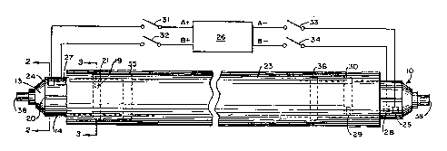
Fig. 1 is a front elevational view of a first
embodiment of the roller of the present invention;
Fig. 2 is a cross sectional view taken in the plane
indicated by line 2--2 in Fig. l;
10Fig. 3 is a cross sectional view taken in the plane
indicated by line 3--3 in Fig. l;
Fig. 4 is a left end fragment of a longitudinal
section of the roller of Fig. l;
Fig. 5 is a front elevational view of a second
embodiment of the roller of the present invention;
Fig. 6 is a cross sectional view taken in the plane
indicated by line 6--6 in Fig. 5;
Fig. 7 is a sectional view taken in the plane
indicated by line 7--7 in Fig. 5; and
20Fig. 8 is a view of a longitu~ l section of a third
embodiment of the present invention.
net~;le~ nescr;~t;on of t~e Preferred Fmho~;mPnt
Fig. 1 shows a preferred embodiment of a heater roller
10 of a type for use in copying machines, or in other
industrial applications, such as steam-heated or induction-
heated rollers for the printing, paper, film, and foil
converting industries.
The f;n;she~ roller 10 includes a hollow cylindrical
core 11 (Fig. 2) with suitable journal shafts 38 (Fig. 1)
for disposition in suitable machine bearing structures of a
type known in the art. The core material in the preferred
embodiment is alllm;nllmr but stainless steel, brass, some
r~ 2 l 66082
WO95/010~ PCT~S94/01159
_ -5-
steels, glass, or an FRP composite type material can also
be used.
If the core 11 includes a conducting material such as
alum;nllm, a thin layer of ceramic insulating material 12 of
approximately 10 mils thickness (1 mil = .001 inches) is
formed over the full outer surface of the core 11 (Figs. 2
and 4). The ~hickness is selected to provide electrical
isolation from ground at the temperature and voltage at
which the roller is used. This insulating layer 12 can be
formed by plasma spraying with an alumina ceramic powder,
such as Metco 101 or 105, or preferably zirconia, Metco 201
or 204, available from Metco Corp., Westbury, New York,
USA. Zirconia can be used as an electrically insulating
barrier coating a few mils thick. In thicker layers,
zirconia is an effective thermal barrier coating due to its
low ~hermal conductivity. It can be plasma sprayed in
layers of 250 mils thick (1/4 inch) or greater.
Next, a plurality of metallic electrode strips 13, 14,
15 and 16 (Figs. 1 and 2) are formed by plasma spraying a
layer of nickel-aluminide, nickel, alllm;nllm, zinc, nickel-
chromium or stainless steel to a thickness of approximately
2 mils, or such other suitable thickness for carrying the
necessary electrical heating current.
The four metallic electrode strips 13, 14, 15 and 16,
each occupy a one-quarter longitll~;n~l section of the
cylindrical surface of the roller core 11. Before
spraying, strips of a tape of 1/4 inch or less are applied
every 90 around the roller core to define the longitll~i n~l
quarter sections. This tape can be a fiberglass tape, a
fiberglass-reinforced silicone tape or a metal foil tape,
which will withstand plasma spraying. After spraying the
tape is removed to create spaces 20 (Fig. 2) between the
electrodes that separate and electrically insulate the
electrode strips 13, 14, 15 and 16 from one another.
Next, a second ceramic insulating layer 17 of 10 mils
in thickness (Fig. 3) is formed over the outer surface of
WO95/01081 -!l~ A ~ ~ 2 1 6 6 0 8 2 PCT~S94/01159
--6--
the strips 13, 14, 15 and 16. This layer can be made of
the same material and in the same thickness as the first
insulating layer 12. This layer 17 has four small areas
which are masked to provide apertures 18 in the layer 17
when the masks are removed. Each aperture 18 leads to one
of the four electrode strips 13, 14, 15, 16. The
insulating layer 17 is shorter on the ends than the
electrode strips 13, 14, 15 and 16, so that the ends of the
strips 13-16 are exposed as seen in Fig. 1.
The next layer to be applied is a sprayed metal layer
of the same materials as were used for the strip
electrodes. The sprayed metal forms feedthrough plugs 19
which fill the apertures 18. Areas on the insulating layer
17 are masked to define conductive bands or rings 21, 30
and 35-36 encircling the roller core 11. Each band or ring
21, 30 and 35-36 connects to a respective feedthrough 19,
29 and to a respective strip electrode 13, 14, 15 or 16.
This is followed by applying a semiconductive ceramic
heater layer 22 (Figs. 3 and 4). The thickness is based on
the area to be heated, operating temperature, and power
supply voltage. In this example, the thickness is
approximately 2 mils.
The outer surface of the roller is provided by a
functional layer 23 of silicone rubber, ceramic, or
tungsten carbide or a metal sleeve. If the outer
functional layer 23 is formed of an electrical conductor,
such as stainless steel, nickel, or tungsten carbide/cobalt
composite, this outer layer 23 is connected to a grounded
negative (-) side of the power supply (Fig. 5). If the
outer layer 23 is made of metal, it can be insulated from
the heater layer by an insulating ceramic layer 39 (Figs. 3
and 4).
The second insulating layer 17 and the ceramic heater
layer 22 are made shorter than the strip electrodes 13, 14,
15 and 16. The electrodes 13-16 are thus exposed at their
WO95/01031 ` ~".- 2 1 6 6 0 8 2 PCT~S94/01159
ends for contact by electrical brushes, represented by
elements 24 and 25.
The brushes 24 and 25 rotate with their respective
electrodes 13, 14 to maintain contact with electrodes 13,
14. The brushes 24, 25 can be arranged to slide on the
insi.de of a ring or race encircling the exposed end of the
roller. Thus, it should be understood that Fig. 1 is a
schematic diagram insofar as brushes 24, 25 are shown
electrically connected to the first positive (A+) voltage
terminal of voltage source 26 and first negative (A-)
(ground) terminal of voltage source 26.
Brush 24 contacts an electrode strip 13 (Figs. 1 and
2) to place positive voltage (A+) on that electrode 13
while brush 25 contacts the second electrode strip 14 (Fig.
2) to place voltage (A-) on that electrode 14. Two more
brushes 27, 28 (shown in phantom in Figs. 1 and 2) would
contact the other two electrode strips 15, 16 at opposite
ends of roller 10 and rotate with elements 15, 16 to apply
voltage (B+) on electrode 15 and voltage (B-) on electrode
16 . As used herein, the term ~brushes~ should be
understood to include all types of devices for making
electrical contact with roller surfaces.
The voltage source 26 may supply either AC or DC
voltage. Switches 31-34 (Fig. 1) are provided to apply
either voltage A to the roller 10 or voltage B. When
voltage A is applied, current is conducted through strips
13, 14, feedthroughs 19, 29 and conductive bands 21, 30 and
through a length of ceramic layer 22 between bands 21 and
30. When voltage B is applied, current is conducted
30 through strips 15, 16, feedthroughs (not shown) and
conductive bands 35, 36 and through a length of ceramic
layer 22 between bands 35 and 36. When voltage B is
applied, the length of the roller 10 that is subjected to
primary heating is shorter than in the case where voltage A
3 5 is applied. This may be used to control heating along the
leng~h of the roller 10 and at the ends of the roller 10.
WO95/01081 ~ C 2 1 6 6 0 8 2 PCT~S94/01159 ~
--8--
The m; n; mllm number of bands for practicing this
embodiment of the invention is two. By moving the two
bands towards the longitll~;n~l center of the roller,
different heating characteristics may be provided. With
four bands, heating becomes selectable and switchable
without changing rollers.
The preferred material for the ceramic heating layer
22 is titanium dioxide, such as Metco 102 ceramic powder.
This is commercially available from Metco Corp., Westbury,
New York, USA. Titanium dioxide (TiO2) is normally an
electrical insulating material. However, when the material
is plasma-sprayed, some of the dioxide form is chemically
reduced to a conductive sub-oxide (mono-oxide) form,
rendering the deposited coating electrically
semiconductive.
As used herein, the term ~conductive~ material shall
mean a material with a volume resistivity of 103 ohm-
centimeters or less. The term ~insulatingU material shall
mean a material with a volume resistivity of 101 ohm-
centimeters or greater. As used herein, the term~semiconductive~ material shall mean a material with a
volume resistivity between 103 ohm-centimeters and 1010
ohm-centimeters. Chromium oxide is an example of a
semiconductive or lower resistance ceramic material. The
unsprayed powder is Cr2O3; after spraying the material may
be Cro or CrO2.
Titanium dioxide can be used as the only component of
the heater layer or it can be blended with other ceramics
or metals to increase or decrease the volume resistivity of
the final coating. For example, insulating ceramics such
as zirconia or alumina can be blended with semiconductive
ceramics such as chromium oxide, or with conductive metals
such as nickel, milled steel, stainless steel or other
alloys, or al~lm;mlm.
Plasma spraying of a ceramic-metal mixture changes the
porosity of the ceramic coating to reduce thermally induced
WO 95/010$1 r !~ ~ ~ 2 1 6 6 0 8 2 PCT~S94/01159
" ~
_9_
stress during its service life, and m; n;m; zes thermal
expansion differences between the metallic core and ceramic
layers over the usable temperature range of the roller.
Plasma spraying, which is one type of thermal
spraying, is advantageous in adjusting the thickness of the
coating to control the electrical resistance of the
titanium dioxide portion of the heater layer.
For any ceramic layer cont~;ning titania (titanium
dioxide), the resistance of the layer is also affected by
the spraying conditions. Titania can be partially reduced
to a suboxide by the presence of hydrogen or other reducing
agents in the plasma flame. It is the suboxide (probably
TiO rather than TiO2) that is the semiconductor in the
ceramic layer 22. Titanium dioxide is normally a
dielectric material. The typical average chemical
composition of titanium dioxide is 1.8 oxygen per molecule
rather than 2.0 in a plasma sprayed coating. This level
(and thus the coating properties) can be adjusted to some
extent by raising or lowering the percentage of hydrogen in
the plasma flame. The normal primary gas is nitrogen or
argon while the secondary gas is hydrogen or helium. The
secondary gas raises the ionization potential of the
mixture, thus increasing the power level at a given
electrode current. For a typical Metco plasma gun, the
hydrogen level is adjusted to maintain the electrode
voltage in the gun between 74 and 80 volts.
Regardless of the mixture of powders used, the plasma
spray parameters should be suitably adjusted to insure that
the blend of materials in the f;n;~hed ceramic layer 22 is
the same as intended. All of the powders mentioned do not
require the same power levels, spray distance, and other
parameters. Thus, adjustment of spray distance, for
- example, may increase the deposit efficiency of one powder
over the other and change the material blend in the
finished coating.
WO 95101081 ~ - r~ 2 1 6 6 0 8 2 PCT~S94/01159 ~
--10--
Plasma sprayed ceramic coatings can be applied in one
pass (layer) of the plasma gun or in multiple passes. The
normal method for most types of coating applications is to
apply multiple thin coatings of ceramic and build up to the
re~uired thickness. Although the ceramic layer described
above has a uniform ceramic composition, the sublayers of
ceramic in the resulting layer 22 do not have to have the
same compositlon.
The hydrogen level can be varied during the
application of each spray pass to apply a titanium dioxide
layer that has a non-uniform electrical resistance from end
to end of the roller. This would normally be done to apply
more heat to the ends of the roller, where the heat losses
are greater, to achieve a uniform temperature across the
roller face in its functional environment.
The thickness of the heater layer 22 can be adjusted
to provide the a~G~riate resistance for the application.
The heater layer 22 may vary in total thickness from about
1 mil to about 100 mils depending on the roller diameter
and length, operating temperature, wattage throughput and
power supply voltage. In the preferred embodiment, the
heater layer 22 is approximately 2 mils thick.
Plasma-sprayed ceramic can be applied in very thin
layers (at least as low as 0.1 mil per spray pass). For
many heating applications, the heater layer formed by
plasma-spraying thin layers will provide a minimal
temperature variation due to thickness variation of the
resulting layer.
The temperature uniformity depends primarily on the
thickness uniformity of the heater layer. Since the heater
layer is composed of many, thin layers or spray passes,
material variation is generally not an issue.
Precise control of the heater layer thickness can be
achieved by conventional grinding of the ceramic layer.
The outer layer 23 can be metal, ceramic, or silicone
rubber alone, or the outer layer 23 can comprise ceramic or
wo 95/01081 2 1 6 6 0 8 2 PCT~S94/01159
.. .
--11--
silicone rubber formed over a replaceable metal sleeve. In
one example, the ceramic 22 is sealed, and an outer
functional layer, preferably silicone rubber is bonded to
the electroplate, which is deposited on the outer surface
of the ceramic heater layer 22. The electroplate must not
contact the core.
The outer functional layer 23 can be plasma sprayed
metal, provided that the metallic layer is insulated from
the heater layer 22 by an insulating ceramic layer 39 of 10
mils thickness. The outer functional layer 23 would be
plasma sprayed and bonded to the ceramic insulating layer
39. Such outer metallic layer 23 would preferably be a
nickel alloy, stainless steel, low resistance cermet or
tungsten carbide composite.
The outer functional layer 23 may be formed over a
metallic sleeve of nickel, steel, or al~lm;nllm, that is
removable and replaceable. The outer functional layer 23
. is then bonded to the replaceable sleeve. The ceramic
heater layer 22 would be ground and sealed in this case to
provide control of the diameter of the roller prior to
fitting of the metallic sleeve. If the outer functional
layer 23 is damaged or wears out, the roller can be
returned to service simply by installing a new sleeve.
xn a second embodiment seen in Figs. 5, 6 and 7,
current flows in a radial direction from elements 43-46
near the core 40 to an outer grounded layer 64. As seen in
Fig. 6, the roller 10 is formed around a hollow,
cylindrical metal core 40, which extends between suitable
journal shafts 41 for supporting the roller 10 in suitable
journal bearings. An insulating ceramic layer 42 is formed
to cover the main body of the core 10, excluding end caps
and journal shafts 41. This layer 42 is formed in the
manner described for layer 12 in the first embodiment.
Four conductive strips 43, 44, 45 and 46, similar to
strips 13-16 in Figs. 1-4, extend longitll~;n~lly over the
surface of layer 42, each covering slightly less than a 90-
WO9S/01081 ~ PCT~S94/01159
degree ~uadrant of the circumference of layer 42, thestrips 43-46 being electrically separated by narrow gaps 57
formed by masking operations. A second ceramic insulating
layer 47, like layer 17 in Figs. 1-4, is disposed over and
around the four metallic strips 43-46, except for the
opposite ends of the strips 43-46, which remain exposed.
The insulating layer 47 is formed with apertures 48,
which are then filled by feedthrough conductors 49, 50, 51
and 52, similar to the formation of conductors 19, 29 in
Figs. 1 and 4. Next, a metallic conductive layer divided
into four wide bands 53, 54, 55 and 56 is disposed over and
around the insulating layer 47, each band 53, 54, 55 and 56
being connected to a respective one of the feedthrough
conductors 49, 50, 51 and 52, and the bands being separated
by relatively narrower gaps 60 formed by masking narrow
bands between the conductive bands 53, 54, 55 and 56.
Thus, each band 53, 54, 55 and 56 covers just under one-
quarter of the circumference of the roller 10 excluding
the exposed ends of strips 43-46.
A ceramic heater layer 62 is formed as described for
layer 22 in Figs. 3 and 4, and is disposed around the
circumference of the roller core to cover conductive bands
53, 54, 55 and 56. An outer functional layer 64 can then
be formed of a metal sleeve which is disposed over and
around the ceramic heater layer 62. An outer functional
layer can be also be formed of silicone rubber or ceramic
placed over a grounded metal layer such as layer 64.
A voltage source 70 in Fig. 5 supplies positive
voltages A+, B+, C+ and D+ through switches 71-74 to
electrical brushes 66-69 which contact respective electrode
strips 43-46. It should be understood that the electrical
connection of brushes 66-69 is schematic in nature, and
that mechanically, the brushes 66-69 would rotate with the
roller 10 within rings or races encircling the ends of the
roller 10 . The brushes 66-69 apply a positive voltage
near the insulated core 40 of the roller. A fifth brush 65
-;j,;A ~
WO95/OlO'B1 2 ~ 6 6 0 8 2 PCT~S94/01159
-13-
contacts the metallic layer 64 to hold it at ground
potential. Current flows between the electrode strips 43-
46 and the outer functional layer 64 through wide
conductive bands 53-56 and corresponding areas of the
ceramic heater layer 62. By applying the B+ and C~
voltages through the middle bands 54, 55, only a middle
portion of the roller 10 is heated. By adding the A+ and
D+ voltages through the outside bands 53, 56 the effective
length of the roller 10' is heated.
The minimum number of bands for practicing this
embodiment of the invention is two. By varying the width
of two bands along the length of the roller, different
heating characteristics may be provided. With four bands,
heating becomes selectable and switchable without changing
rollers. The various zones can also be maintained at the
same or different temperatures rather than just being
active or non-active.
Referring next to Fig. 8, the invention may also be
embodied in a roller in which the layers are inside the
core. In Fig. 8, roller 80 includes steel core 81, a
ceramic heat-regulating layer 82, and a ceramic heating
layer 83. Electrode band 84 runs around the inner
circumference of the roller 80, and is electrically
connected to terminal 92. Electrode band 85 runs around
the inner circumference of the roller 80, and is
electrically connected to terminal 93. Electrode band 86
runs around the inner circumference of the roller 80, and
is electrically connected to terminal 95. Electrode band
87 runs around the inner circumference of the roller 80,
and is electrically connected to terminal 94. Steel core 81
is co1mected to ground terminal 97.
I~hen layer 83 rotates, bands 84-87 move with it but
remain in contact with respective stationary contacts (not
shown~. Four insulated wires 90 extend through an opening
in a journal shaft 89, which is mounted in ~nnn~ ~r end cap
88 enclosing one end of the hollow roller core 80.
2 1 66082
WO9~/01081 ~ PCT~S94/01159
-14-
Term;n~l~ 92-95 are connected to a slip ring assembly, such
that the wires electrically connecting terminals 92-95 and
bands 84-87 remain stationary as the roller 80 rotates.
This roller 80 is operated for zone heating by
applying voltages across any pair of the terminals 84-87,
for example, positive voltage (+V) at terminal 85 and
ground potential (GND) at terminal 84. Electrical current,
represented by arrows 91, flows from band 85 to band 84,
principally through the heat regulating layer 82, and iater
in layer 83, if resistance in layer 83 decreases
sufficiently with heating. By applying the voltages to
various bands 84-87 for various lengths of time, heating
can be controlled in middle section between bands 85 and
86, and in end sections that are located between pairs of
bands 84, 85 and 86, 87.
Thus, it should be apparent that the zone heating
concepts of the present invention are applicable to a
roller with layers formed around an outside diameter, or a
roller with layers formed around an inside diameter.
This has been a description of examples of how the
invention can be carried out. Those of ordinary skill in
the art will recognize that various details may be modified
in arriving at other detailed embodiments, and these
embodiments will come within the scope of the invention.
Therefore, to apprise the public of the scope of the
invention and the embodiments covered by the invention, the
following claims are made.