Sélection de la langue

Search

Sommaire du brevet 2166269 

Énoncé de désistement de responsabilité concernant l'information provenant de tiers

Une partie des informations de ce site Web a été fournie par des sources externes. Le gouvernement du Canada n'assume aucune responsabilité concernant la précision, l'actualité ou la fiabilité des informations fournies par les sources externes. Les utilisateurs qui désirent employer cette information devraient consulter directement la source des informations. Le contenu fourni par les sources externes n'est pas assujetti aux exigences sur les langues officielles, la protection des renseignements personnels et l'accessibilité.

Disponibilité de l'Abrégé et des Revendications

L'apparition de différences dans le texte et l'image des Revendications et de l'Abrégé dépend du moment auquel le document est publié. Les textes des Revendications et de l'Abrégé sont affichés :

  • lorsque la demande peut être examinée par le public;
  • lorsque le brevet est émis (délivrance).
(12) Brevet: (11) CA 2166269
(54) Titre français: GARNITURE D'ETANCHEITE DE DIAPHRAGME A FICHE
(54) Titre anglais: PUSH PLUG SEAL
Statut: Périmé et au-delà du délai pour l’annulation
Données bibliographiques
(51) Classification internationale des brevets (CIB):
  • B62D 25/24 (2006.01)
  • B60R 13/00 (2006.01)
(72) Inventeurs :
  • HARTERY, WILLIAM (Etats-Unis d'Amérique)
(73) Titulaires :
  • ILLINOIS TOOL WORKS INC.
(71) Demandeurs :
  • ILLINOIS TOOL WORKS INC. (Etats-Unis d'Amérique)
(74) Agent: FINLAYSON & SINGLEHURST
(74) Co-agent:
(45) Délivré: 1999-01-19
(22) Date de dépôt: 1995-12-28
(41) Mise à la disponibilité du public: 1996-07-27
Requête d'examen: 1995-12-28
Licence disponible: S.O.
Cédé au domaine public: S.O.
(25) Langue des documents déposés: Anglais

Traité de coopération en matière de brevets (PCT): Non

(30) Données de priorité de la demande:
Numéro de la demande Pays / territoire Date
378,518 (Etats-Unis d'Amérique) 1995-01-26

Abrégés

Abrégé français

Dispositif d'étanchéité à bouchon-poussoir et méthode de fabrication de ce produit. Ce dispositif comporte une série d'ergots pointus qui transpercent la pièce de scellage avec laquelle ils s'engagent avant d'être repliés.


Abrégé anglais


A push plug seal and method of manufacturing the
same provides a series of sharp-pointed tabs that lance
into and are bent over to engage a sealer patch.

Revendications

Note : Les revendications sont présentées dans la langue officielle dans laquelle elles ont été soumises.


- 7 -
What is claimed is:
1. A push plug, comprising:
a metal one-piece plug for sealing an aperture
extending through a vehicle body panel, said plug having
a plug body having at least two gripping legs extending
generally perpendicularly away from said plug body, said
legs each having two sets of gripping tabs for gripping
said aperture, one set of tabs being located intermediate
said body and free ends of said legs thereby providing a
first mounted position and a second set of tabs located
adjacent said free ends of said legs thereby providing a
final mounted position, said plug body having a plurality
of substantially triangular sharp-pointed tabs located
intermediate said legs around a perimeter of said plug
body and extending perpendicularly away from said plug
body oppositely from said legs;
an elastomeric sealing patch located against said
plug body on a side of said plug body whereby said sharp-
pointed tabs penetrate the patch and retain the patch to
said plug body.
2. A push plug in accordance with claim 1 wherein
ends of said sharp-pointed tabs are folded over to retain
said patch to said plug body.
3. A push plug in accordance with claim 1 wherein
there are three of said gripping legs.
4. A push plug, comprising:
a metal one-piece plug for sealing an aperture
extending through a vehicle body panel comprising: a plug
body having at least two gripping legs extending
generally perpendicularly away from said plug body, said

- 8 -
legs each having gripping tabs for gripping said
aperture, said plug body having a plurality of sharp-
pointed tabs located intermediate said legs around a
perimeter of said plug body and extending perpendicularly
away from said plug body oppositely from said legs;
an elastomeric sealing patch located against said
plug body on a side of said plug body whereby said sharp-
pointed tabs penetrate the patch and retain the patch to
said plug body.
5. A push plug in accordance with claim 4 wherein
ends of said sharp-pointed tabs are folded over to retain
said patch to said plug body.
6. A push plug in accordance with claim 4 wherein
there are three of said gripping legs.
7. A push plug, comprising:
a metal one-piece plug for sealing an aperture
extending through a vehicle body panel comprising: a plug
body having at least two gripping legs extending
generally perpendicularly away from said plug body, said
legs each having gripping tabs for gripping said
aperture, said plug body having a plurality of sharp-
pointed tabs located intermediate said legs around a
perimeter of said plug body and extending perpendicularly
away from said plug body oppositely from said legs;
an elastomeric sealing patch located against said
plug body on a side of said plug body whereby said sharp-
pointed tabs penetrate the patch and are bent over to
retain said patch to said plug body.
8. A push plug in accordance with claim 7 wherein
there are three of said gripping legs.

- 9 -
9. A method of manufacturing a push plug,
comprising the steps of stamping a plug blank having at
least two gripping legs, said legs each having gripping
tabs for gripping said aperture, said plug blank having
a plurality of sharp-pointed tabs located intermediate
said legs around a perimeter of said plug blank;
bending said legs to extend perpendicularly from
said plug blank;
bending said sharp-pointed tabs to extend
perpendicularly away from said plug blank oppositely from
said legs;
placing said plug blank against a strip of an
elastomeric sealing patch material;
penetrating said sealing patch material with said
sharp-pointed tabs and folding over said tabs to secure
said patch to said plug blank;
cutting said patch material to a desired shape and
separating said cut patch material from said strip of
patch material.

Description

Note : Les descriptions sont présentées dans la langue officielle dans laquelle elles ont été soumises.

2166269
Docket No. -25-?OG79A
PUSH DLUG SEAL
Field of the ;nvention:
: The present nvention relates to an seal for a snap
plug or push plug of the type used to seal apertures in
automobile body parts after painting.
DescriDtion of the Prior Art
A variety of plug assembl~es are known in .he art as
suitable to close or seal an aperture such as paint drain
holes in an automobile body. The apertures permit paint
to drain after the automobile body is dipped into paint
or other coatings to minimize waste and uneven
application of the paint or other coatings. Typical known
push plugs include those described in U.S. Patent No .
4,809,872 and others. The plugs typically include a
series of gripping fingers that are formed with the plug
to grip the lip of an aperture in a car body, and a heat
activated sealer is used in conjunction therewith.
Heretofore, such sealers are typically located between
the plug body and the automotive body, and have been
annular in shape. In some cases, a circular sealer is
fas~ened to the plug on its outer face by heat wherein
the sealer is bonded to the metal plug body in a central
area of the plug.
SUMM~RY OF THE INVENTION
It is an obiect of the invention to provide an
improved push plug and method of manufacturing the push
plug that is more economical to manufacture and more
sturdy than prior art plug assemblies.

2166269
A push piug in acco-dance with one embodiment or the
invention comprises a metal plug and a seaier paLch
secured thereto by self-lancing tabs. In par~icular, the
plug comprises a metal one-piece plug body having at
S least two gripping legs and preferably three such iegs
extending generally perpendicularly away from the plug
body. The legs have gripping tabs for gripping the
aperture in an automobile body. The plug body has a
plurality of substantially triangular sharp-pointed tabs
located intermediate the legs around a perimeter of the
plug body and extending perpendicularly away frcm the
plug body oppositely from the legs. The elastomeric
sealing patch is located against the plug body on a side
of the plug body whereby the sharp-pointed tabs penetrate
the patch and retain the patch to the piug body. The
sharp-pointed tabs are folded over to retain the patch to
the plug body.
A method of manufacturing a push plug in accordance
with one embodiment of the invention comprises the steps
of stamping a plug blank. The stamped plug blank has at
least two, and preferably three, gripping legs. The legs
each have gripping tabs for gripping an aperture to be
covered by the plug. The blank has a plurality of sharp-
pointed tabs located intermediate the legs around a
perimeter of the plug blank. The legs are progressively
bent in a progressive die to extend perpendicularly from
the plug blank, with the gripping tabs extending
outwardly from the legs. The sharp-pointed tabs are bent
to extend perpendicularly away from the plug blank
opposite frcm the legs. The plug biank is then placed
against a strip of an elastomeric sealing patch material,
and the patch material is pierced by the sharp-pointed
tabs. The tabs are folded over to secure the patch to the

2166269
plug D7 ank. The patch material is cut, preferably
simultaneously with the tab folding step, to a desired
shape and is separated from the strip of patch material.
Other objects, aspects and features of the present
invention in addition to those mentioned above will be
pointed out in or will be understood from the following
detailed description provided in conjunction with the
accompanying drawings.
BRIEF DESCRIPTION OF THE DRAWINGS
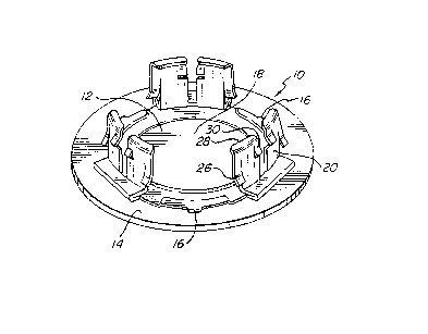
FIG. 1 is a perspective view of an embodiment of an
improved push plug in accordance with the invention.
FIG. 2 is a bottom plan view of the embodiment of
the push plug of FIG. 1.
FIG. 3 is a top plan view of the embodiment of the
push plug of FIG. 1.
FIG. 4 is a cross-sectional view of the embodiment
of the push plug of FIG. 1 along the line 4-4.
FIG. 5 is a detail view of the sharp pointed tabs of
the plug of FIG. 1 engaged with a sealer patch.
DETAILED DESCRIPTION OF
THE PREFERRED EMBODIMENT
Referring now to FIGS. 1-5, where like numerals
indicate like elements in the drawings, an improved push
plug 10 in accordance with one embodiment of the
invention is shown. Push plug 10 comprises a metal plug
12 and a sealer patch 14 secured to plug 12 by self-

216626g
lancing tabs 16. In partlcular, the plug comprises a
metal one-piece plug body 18 having at least two gripping
legs 20 extending generally perpendicularly away from the
plug body 18. Preferably there are three such gripping
legs 20 for use with most size apertures, although in
some instances, for example, where the plug 10 is to be
- used with a relatively smaller size aperture, only two
such gripping legs 20 may be desirable.
Legs 20 have gripping tabs 22 for gripping the
aperture in an automobile boay. Preferably there are two
sets of gripping tabs 22 on each leg for gripping the
aperture. In such case, one set of tabs 26 is located
intermediate the body 18 and free ends 28 of the legs 20,
thereby providing a first mounting position when the plug
legs are inserted into the aperture. A second set of tabs
30 is located adjacent the free ends 28 of legs 20
thereby providing a final mounting position with the plug
body 18 fIush against the aperture of the automobile
body.
Plug body 18 has a plurality, preferably three,
substantially triangular sharp-pointed tabs 16 located
intermediate the legs 20 around a perimeter of the plug
body 18. Preferably the three tabs 16 are located about
. _,,
120 degrees apart. Sharp-pointed tabs 16 extend
perpendicularly away from the plug body 18 in a direction
oppositely from the direction that legs 20 extend. The
elastomeric sealing patch 14 is located against the plug
body on a side 24 of the plug body 18 whereby the sharp-
pointed tabs 16 penetrate the patch 14 and retain the
patch 14 to the plug body 18. The sharp-pointed tabs 16
are folded over to retain the patch 14 to the plug body
18.

2166269
-
The elastomeric patch 14 is affected by heat sucn
that subsequent heating of the patch 14 will cause it to
weld to the automobile body to provide a secure,
watertight seal.
A method of manufacturing a push plug iO in
accordance with one embodiment of the invention comprises
the steps of stamping a plug blank. The stamped plug
blank has a body 18 and at least two, and preferably
three gripping legs 20. The legs 20 each have gripping
tabs 22 for gripping an aperture to be covered by the
plug 10. The blank has a plurality of sharp-pointed tabs
16 located intermediate the legs 20 around a perimeter of
the plug blank. The legs 20 are bent in a progressive die
to extend perpendicularly from the plug blank with the
gripping tabs extending outwardly from the legs 20. The
sharp-pointed tabs 16 are bent to extend perpendicularly
away from the plug blank opposite from the legs 20. The
plug blank is then placed against a strip of an
elastomeric sealing patch material, and the patch
material is pierced by the sharp-pointed tabs 16. The
tabs 16 are folded over to secure the patch to the plug
blank. The patch material is cut, preferably
simultaneously with the tab folding step, to a desired
shape and is separated from the strip of patch material.
The present invention improves over prior art
devices by eliminating the need for the welding step
needed to secure the sealer to the plug in prior art
devices. This reduces electrical consumption costs, and
provides a secure, mechanical fastening.

216626~
In addition, the invention provides the seal on the
outside or the plug to provide an unusually secure and
watertight seal.
It is to be appreciated that the foregoing is
illustrative and not limiting of the invention, and that
various changes and modifications to the preferred
embodiments described above will be apparent to those
skilled in the art. Such changes and modifications can be
made without departing from the spirit and scope of the
present invention, and it is therefore intended that such
changes and modifications be covered by the following
clalms .

Dessin représentatif
Une figure unique qui représente un dessin illustrant l'invention.
États administratifs

2024-08-01 : Dans le cadre de la transition vers les Brevets de nouvelle génération (BNG), la base de données sur les brevets canadiens (BDBC) contient désormais un Historique d'événement plus détaillé, qui reproduit le Journal des événements de notre nouvelle solution interne.

Veuillez noter que les événements débutant par « Inactive : » se réfèrent à des événements qui ne sont plus utilisés dans notre nouvelle solution interne.

Pour une meilleure compréhension de l'état de la demande ou brevet qui figure sur cette page, la rubrique Mise en garde , et les descriptions de Brevet , Historique d'événement , Taxes périodiques et Historique des paiements devraient être consultées.

Historique d'événement

Description Date
Le délai pour l'annulation est expiré 2004-12-29
Lettre envoyée 2003-12-29
Accordé par délivrance 1999-01-19
Inactive : Taxe finale reçue 1998-09-04
Préoctroi 1998-09-04
Un avis d'acceptation est envoyé 1998-03-16
Lettre envoyée 1998-03-16
Inactive : Renseign. sur l'état - Complets dès date d'ent. journ. 1998-03-09
Inactive : Dem. traitée sur TS dès date d'ent. journal 1998-03-09
Inactive : Approuvée aux fins d'acceptation (AFA) 1998-02-26
Demande publiée (accessible au public) 1996-07-27
Exigences pour une requête d'examen - jugée conforme 1995-12-28
Toutes les exigences pour l'examen - jugée conforme 1995-12-28

Historique d'abandonnement

Il n'y a pas d'historique d'abandonnement

Taxes périodiques

Le dernier paiement a été reçu le 1998-12-18

Avis : Si le paiement en totalité n'a pas été reçu au plus tard à la date indiquée, une taxe supplémentaire peut être imposée, soit une des taxes suivantes :

  • taxe de rétablissement ;
  • taxe pour paiement en souffrance ; ou
  • taxe additionnelle pour le renversement d'une péremption réputée.

Les taxes sur les brevets sont ajustées au 1er janvier de chaque année. Les montants ci-dessus sont les montants actuels s'ils sont reçus au plus tard le 31 décembre de l'année en cours.
Veuillez vous référer à la page web des taxes sur les brevets de l'OPIC pour voir tous les montants actuels des taxes.

Historique des taxes

Type de taxes Anniversaire Échéance Date payée
TM (demande, 2e anniv.) - générale 02 1997-12-29 1997-12-16
Taxe finale - générale 1998-09-04
TM (demande, 3e anniv.) - générale 03 1998-12-29 1998-12-18
TM (brevet, 4e anniv.) - générale 1999-12-28 1999-12-02
TM (brevet, 5e anniv.) - générale 2000-12-28 2000-12-01
TM (brevet, 6e anniv.) - générale 2001-12-28 2001-12-03
TM (brevet, 7e anniv.) - générale 2002-12-30 2002-11-29
Titulaires au dossier

Les titulaires actuels et antérieures au dossier sont affichés en ordre alphabétique.

Titulaires actuels au dossier
ILLINOIS TOOL WORKS INC.
Titulaires antérieures au dossier
WILLIAM HARTERY
Les propriétaires antérieurs qui ne figurent pas dans la liste des « Propriétaires au dossier » apparaîtront dans d'autres documents au dossier.
Documents

Pour visionner les fichiers sélectionnés, entrer le code reCAPTCHA :


Pour visualiser une image, cliquer sur un lien dans la colonne description du document. Pour télécharger l'image (les images), cliquer l'une ou plusieurs cases à cocher dans la première colonne et ensuite cliquer sur le bouton "Télécharger sélection en format PDF (archive Zip)" ou le bouton "Télécharger sélection (en un fichier PDF fusionné)".

Liste des documents de brevet publiés et non publiés sur la BDBC .

Si vous avez des difficultés à accéder au contenu, veuillez communiquer avec le Centre de services à la clientèle au 1-866-997-1936, ou envoyer un courriel au Centre de service à la clientèle de l'OPIC.


Description du
Document 
Date
(aaaa-mm-jj) 
Nombre de pages   Taille de l'image (Ko) 
Dessin représentatif 1999-01-07 1 10
Abrégé 1996-04-23 1 7
Description 1996-04-23 6 211
Revendications 1996-04-23 3 101
Dessins 1996-04-23 2 48
Dessin représentatif 1998-04-30 1 14
Rappel de taxe de maintien due 1997-08-30 1 111
Avis du commissaire - Demande jugée acceptable 1998-03-15 1 165
Avis concernant la taxe de maintien 2004-02-22 1 175
Correspondance 1998-09-03 1 31
Correspondance de la poursuite 1995-12-27 2 50