Note : Les descriptions sont présentées dans la langue officielle dans laquelle elles ont été soumises.
2166~28
-
SURGICAL ATTACHMENT DEVICE
BACKGROUND
The present invention relates generally to medical equipment, and more
particularly, to a surgical attachment device that is used to secure tubes, wires, hoses,
electrical cables, video cables and fiber optic cables during an operation.
During surgical operations, it is customary for surgeons and other operating
room personnel to employ suction tubes to remove blood, tissue and other cellular
debris from a patient that is undergoing an operation, and air-driven pneumatic tools
that are driven by an air source(s) coupled to the tools by way of pneumatic hoses.
Furthermore, it is customary to use electrosurgical instruments that are used as cutting
and coagulation tools during surgery. These electrosurgical instruments are connected
to electrical equipment by way of electrical cables. Unipolar electrosurgical instruments
transmit current through the patient to a grounding pad, while bipolar electrosurgical
instruments transmit current between the two heads of bipolar forceps. The electrosur-
gical instruments, pneumatic tools, and cables are used in almost all surgeries. More
recently, endoscopic surgery has proliferated. These surgeries require fiber optic light
cables and video camera cables passing to and from the operative field, respectively.
During surgery, it is common practice to store the electrosurgical instruments
and tools in a self-adherent plastic pocket of a drape that is disposed over the patient
when they are not in use. This also provides easy access for the surgeon. The cables
and hoses that connect the electrosurgical instruments and tools to their electrical
equipment, air sources and endoscopic equipment are loosely gathered together adjacent
an extremity of the patient and are secured hy wrapping a portion of the drape around
the cables and then holding them in place using a surgical clamp. In a similar fashion.
the suction tubes are also routed and clamped in place, typically by the same type of
surgical clamp. As should be clear from this typical operating room scenario, the
cables are not very well controlled and in many instances interfere with the operation,
or may become dislodged or cont~min:ltcd.
2166~28
Accordingly, and in order to overco~lne the limitations of conventional operating
room practices, it is an objective of the present invention to provide for a surgical
attachment device that is used to secure tubes, wires, hoses, electrical cables, video
cables and fiber optic cables during an operation.
s
SUMMARY OF THE INVENTION
In order to meet the above and other objectives, the present invention is a
surgical attachment device for securing one or more cylindrically shaped members,
including tubes and/or cables, such as suction tubes, hoses, electrical cables, video
cables and fiber optic cables during an operation. The surgical attachment device
comprises a member, that is preferably comprised of molded plastic, having at least one
opening or groove formed therein adjacent a first surface thereof. A first portion of
each opening is designed to slidably secure a particular cylindrically shaped member,
such as a suction tube, hose, or unipolar, bipolar, or endoscopic cable, for example. A
second portion of each opening immediately adjacent the first surface is dimensioned to
be slightly smaller than the dimension of the first portion of the opening. The first
portion of each opening tapers from a narrow dimension adjacent the center of the
member to a wide dimension adjacent opposite ends of the member.
Each opening has a plurality of inwardly projecting tapered ribs disposed
around its internal periphery that taper from their narrowest dimension adjacent the
center of the opening to their widest dimension at the ends of each opening. Theinwardmost edges of the plurality of tapered ribs have a dimension substantially equal
to or narrower than the narrowest dimension of the tapered opening. The plurality of
tapered ribs assist in securing the cylindrically shaped member in the opening and
prevent unwanted sliding thereof. The inwardmost edges of the ribs contact the
cylindrically shaped member when it is inserted into the opening. A first set of ribs, or
projections, disposed adjacent the interface between the first and second portions of the
opening are larger than the others and prevent inadvertent pull-out of the various tubes,
hoses, wires and cables from the opening.
An adhesive layer is disposed on a second external surface of the member so
that it may be secured to a surgical drape during an operation. The adhesive layer may
be affixed or otherwise coated onto the second surface of the member and a backing
layer may be disposed thereon. The backing layer covers the adhesive layer prior to
use, and is removed to expose the adhesive layer and secure the surgical attachment
device to the drape.
The surgical attachment device may comprise a member that is flexible or
deformable between the first and second portions of each opening to permit passage of
216G~28
-_ 3
noncompressible or fragile cylindrically shaped members through the second portion of
the opening into the first portion thereof. This may be achieved by modifying the
surgical attachment device to include additional lower slots separated from selected
openings by hinge areas that provide for easy flexing of the member at the openings to
5 permit insertion of the tubes, hose, or cables therein. The flexible portion of the
member comprises one or more living hinge areas that flex to open each opening.
BRIEF DESCRIPTION OF THE DRAWINGS
The various features and advantages of the present invention may be more
10 readily understood with reference to the following detailed description taken in
conjunction with the accompanying drawings, wherein like reference numerals
designate like structural elements, and in which:
Fig. 1 shows a typical operating room scenario employing surgical attachment
devices in accordance with the principles of the present invention;
Fig. 2 is an end view of a first embodiment of the surgical attachment device inaccordance with the present invention;
Fig. 3 is a cross sectional top view of the surgical attachment device of Fig. 2taken along the lines 3-3;
Fig. 4 is an end view of a second embodiment of the present surgical attachment
device;
Fig. 5 is a cross sectional top view of the device of Fig. 4 taken along the lines
5-5;
Fig. 6 shows a first end of a third embodiment of the present surgical
m~nt device;
Fig. 7 shows a second end of the device of Fig. 6;
Fig. 8 is a cross sectional top view of the device of Figs. 6 and 7 taken along
the lines 8-8;
Fig. 9 is an end view of a fourth embodiment of the present surgical attachment
device;
Fig. 10 is a cross sectional top view of the device of Fig. 9 taken along the lines
10-10; and
Fig. 11 is an end view of a fifth embodiment of the present surgical attachment
device.
DETAILED DESCRIPTION
Referring to the drawing figures, Fig. 1 shows a typical operating room
scenario employing surgical attachment devices 10 in accordance with the principles of
21~6~2~
the present invention. Fig. 1 shows an operating room table 18 on which is disposed a
surgical drape 17 the is used to cover a patient (not shown) during an operation. The
drape has an opening 17a therein that exposes an area of the patient that is to be
operated on. Self-adhering plastic pockets 16 are attached to the drape 17 in which
surgical instruments 13 may be stored when not in use. Typical surgical instruments
13 include electrosurgical instruments 13 used for cutting and coagulation of tissues,
endoscopic instruments 13 used for minim~lly invasive surgery in various body
cavities, or pneumatic air-driven instruments 13 of all types, intravenous lines and
cardiovascular bypass tubes 11. Flexible intravenous (I-V) tubes 11 are run from I-V
solution bags 14b to the patient. A flber optic light source cable and video cable 12
may be coupled between a light source and video camera 14c and optical instruments
13 that are used to illuminate and view the operative field, for example.
The surgical instruments 13 are connected to electrical equipment 14 (controller14) in a conventional manner by means of unipolar and bipolar electrical cables 12 for
the cauterizing instruments 13, endoscopic cables 12 for the endoscopic instruments
13, and hoses 12a for pneumatic air-driven instruments 13. In addition, suction tubes
11 are coupled to a vacuum pump 15 and are used to remove blood, tissue and other
cellular debris from the patient during the operation. Intravenous tubes 11 passes to the
patient and cardiovascular bypass tubes 11 pass to and from a cardiovascular bypass
pump 14a. A compressed air pump l5a may be coupled to a compressed air tube 11.
The surgical attachment devices 10 of the present invention is used to secure the
respective suction tubes 11 and electrical or endoscopic cables 12, and the like, in an
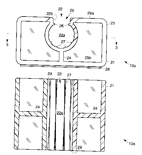
orderly manner during the operation. Fig. 2 is an end view of a first embodiment of
the surgical attachment device lOa in accordance with the present invention. Fig. 3 is a
cross sectional top view of the surgical attachment device lOa of Fig. 2 taken along the
lines 3-3.
The first embodiment of the surgical attachment device lOa is comprised of a
member 21 that may be a block of plastic, such as polyethylene or polystyrene, for
example. The member 21 is a single piece structure that has an outer body 23 with a
plurality of inwardly extending supporting ribs 24 that mate with an opening 22, or
groove 22. The opening 22 or groove 22 is formed adjacent a first surface 29a of the
member 21. The opening 22 may have flared ends 29.
The opening 22 has a first portion 22a that typically has a circular cross section,
and that is sized to secure a particular suction tube 11 or cable 12 therein. A second
portion 25 of the opening 22 comprises a slot 22b that has a dimension that is smaller
than the dimension of the first portion 22a. It is to be understood that while the
embodiment shown in Fig. 2 illustrates an opening or grooves 22 for use with suction
216~28
.
tubes 11 and cables 12, the sizing and number of openings or grooves 22 may be
altered to meet particular requirement for different sized tubes 11 and cables 12.
Consequently, the embodiment of the surgical attachment device lOa shown in Fig. 2
should not be taken as limiting.
The surgical attachment device lOa may have a length of about 1.57 inches, a
width of about 1.95 inches, and a thickness of about 1.00 inches, for example. With
respect to the opening or groove 22 shown in Fig. 2, it may be sized for use with the
pneumatic tube 11, for example, and the first or circular portion 22a may have adiameter of about 0.56 inches, for example. This diameter is outwardly tapered from
lO the center of the flexible member 21 toward each end. This permits removal of the
member 21 from its mold. The width dimension of the slot 22b may be on the order of
0.36 inches in width, for example.
The opening 22 has a plurality of tapered ribs 27 that may be triangular, for
example, disposed along the internal periphery of the opening 22 that taper from their
15 widest dimension at respective ends of the opening 22 to their narrowest dimension
adjacent the center of the opening 22. The plurality of tapered ribs 27 assist in securing
the tube 11 or cable 12 in the groove 22 and prevent unwanted sliding and inadvertent
thereof. The tapered ribs 27 have a diameter adjacent the respective ends of theopening 22 that is substantially equal to or narrower than the diameter of the opening
20 22 at its center (at the location where the tapered ribs 27 start to taper outward). A pair
of projections 26 are present at the interface between the first and second portions 22a,
22b of the opening 22. The pair of projections 26 are larger than the other ribs 27 and
serve to prevent inadvertent pull-out of the hose, cable tube or tube 12 from the
opening 22. A surgical attachment device lOa that includes these projections 26 may be
25 used to secure a pneumatic hose, for example.
An adhesive layer 28 is disposed on a second surface 29b of the member 21 so
that it may be secured to the surgical drape 17 during an operation. The adhesive layer
28 may be comprised of any suitable adhesive, such as those commonly used in
medical applications. The adhesive layer 28 is affixed or otherwise coated onto the
30 second surface 29b of the flexible member 21 and a backing layer (not ~hown) ~uch a~
is provided by wax-coated paper, for example, may be applied to the exposed .surface
of the adhesive layer 28. The backing layer is used to cover the adhesive layer 28 prior
to use, and is peeled off to expose the adhesive layer 28, whereafter the surgical
attachment device 10 is then secured to the drape 17.
Referring to Fig. 4, it is an end view of a second embodiment of the surgical
attachment device lOb, while Fig. 5 is a cross sectional top view of the device lOb of
Fig. 4 taken along the lines 5-5. In the surgical attachment device lOb shown in Figs.
6 21~6~2~
4 and 5, there are first and second openings 22, 31, and the first opening 22 is smaller
than the opening 22 of the device lOb of Fig. 2. The diameter of a first portion 22a of
the first opening 22 may be on the order of 0.34 inches, for example, and is designed
to secure a fiber optic light source cable and video cable 12, for example. The slot 22b
S of the opening 22 is smaller than the diameter of the first portion 22a of the opening 22
and may be on the order of 0.29 inches, for example. The second opening 31 is
formed in the member 21 and is sized for use with a video cable 12 and its first portion
31 a may have a diameter of about 0.18 inches, for example. A slot 31 b of the second
opening 31 may be on the order of 0.17 inches, for example.
In the second embodiment of the surgical attachment device lOb, the member
21 is flexible, and the first and second openings 22, 31 are made to open and close, by
means of respective slots 33a, 33b that create two living hinges 34. The slots 33a, 33b
separate two outer sections of the member 21 from a central section and are caused to
flex by squeezing them toward the central section, thus opening the first and second
openings 22, 31. The living hinges 34 return to their original positions after
deformation of the openings 22, 31. Again, in the second embodiment of the surgical
attachment device lOb, tubes 11 and cables 12, and the like, are secured in the first and
second openings 22, 31 by the use of the ribs 27 that project into the respective
openings 22, 31 and make contact with the respective tube 11 or cable 12.
Referring to Figs. 6 and 7, they show first and second ends of a third
embodiment of the surgical attachment device lOc. Fig. 8 is a cross sectional top view
of the device lOc of Figs. 6 and 7 taken along the lines 8-8. The surgical attachment
device lOc is designed to have three substantially configured openings 22. Theseopenings 22 are designed to hold flexible intravenous (I-V) tubes 11 that is connected
to a commonly-used in-line medication port (not shown) used to add medication tocontinuously running IV fluid, for example. Each opening 22 has a first portion 35a
that includes the plurality of triangular ribs 27 that are used to secure the tubing. The
most superficial ribs 27 (or projections 26) are larger than the rest of the ribs 27 and
serve to restrict inadvertent pull-out of the tubing from the opening 22. A second
portion 35b of the opening 22 is configured to mate with ~nd secure the I-V port. The
second portion 35b of the opening 22 has a taper 36 that tapers from the outer edge of
the second portion 35b of the opening 22 toward the center of the member 21 and
generally matches a tapered portion of the IV port.
Referring to Figs. 9 and 10, they show end and cross sectional top views of a
fourth embodiment of the surgical attachment device lOd. The fourth embodiment of
the surgical attachment device lOd comprises three different sized openings 22, 31, 37.
The second opening 31 is smaller than the first opening 22, and the third opening 37 is
2i66428
smaller than the second opening 31. The diameter of the first opening 22 may be on the
order of 0.34 inches, for example, and is designed to secure suction tubing or cell saver
suction tubing, for example. The diameter of the second opening 31 may be on theorder of 0.12 inches, for example, and is designed to secure a unipolar electrical cable
12, for example. The diameter of the third opening 37 may be on the order of 0.07
inches, for example, and is designed to secure a bipolar electrical cable 12, for
example. The discussion relating to Figs. 2, 3, 4 and 5 describe the attributes of the
structure of the fourth embodiment of the surgical attachment device lOd, and additional
description is not believed to be necessary in understanding the invention.
The fourth embodiment of the surgical attachment device lOb includes living
hinges 34, and the openings 31, 37 in are caused to flex by squeezing two outer
sections of the member 21 toward a middle section thereof, thus opening the openings
31, 37. In the fourth embodiment of the surgical attachment device lOb, tubes 11 and
cables 12, and the like, are secured in the three openings 22, 31, 37 by the use of the
ribs 27 that project minim~lly into the respective openings 22, 31, 37 and make contact
with the respective tube 11 or cable 12.
Due to generally coincident sizes of the openings 22, 31, 37 and ribs 27 and thecables 12, hose, or tube 11 passing through them, a certain amount of friction is
produced. The length of the respective openings 22, 31, 37, in part, determines the
friction or drag that is encountered by the tube 11 or cables 12 passing through them,
when they are pulled or pushed through their respective openings 22, 31, 37. Thelength of the openings 22, 31, 37, the relative dimensions of the openings 22, 31, 37,
and ribs 27, and the tube 11, hose, or cables 12 passing through them, are propor-
tioned to provide optimal control of the tube 11 and cables 12. The ribs 27 are
sufficient to prevent easy pull-out of the tubes 11 or cables 12, while easily allowing
insertion of the tube 11 or cables 12 into their respective openings 22, 31, 37. The
larger ribs 27 or projections 26 that are strategically placed, usually at the entrance to
the opening 22a, prevent inadvertent pull-out of the tube hose, wires and cables.
Fig. 11 is an end view of a fifth embodiment of the present surgical attachment
device lOe. This embodiment of the device lOe is a cardiovascular manifold that
secures multiple tubes 11 and cables 12 that are used in cardiova~scular operations, and
the like. Each of the openings 22 of the member 21 is de~signed as described above and
secures a specific type of tube 11 or cable 12 therein.
It is to be understood that the number of openings 22 disclosed with reference
to each of the embodiments of the device 10 may be only one opening 22 or may be a
plurality of openings 22 as shown in the various disclosed embodiments. Further-
2166~28
more, different variations of the disclosed embodiments may be constructed using the
principles of the present invention to accommodate specific surgical situations.In operation, in the embodiments of the surgical attachment device 10 having
living hinges 34, the tubes 11 or cables 12 are inserted into the openings 22, 31, 37 by
transiently deforming the narrower portion of each groove 22, 23, 24, deforming the
tube 11, hose, or cable 12, or both, and pushing the tube 11, hose, or cable 12 into the
openings 22, 31, 37. In the embodiments of the surgical attachment device 10 having
openings without living hinges 34, the tubes 11 or cables 12 are inserted into the
openings 22 by deforming the tube 11, hose, or cable 12, and pushing the tube l l,
hose, or cable 12 into the openings 22.
Once the tube 11 or cable 12 is within its openings 22, 31, 37, the narrower
portion of the openings 22, 31, 37 restricts unintended pull-out of the tube 11 or cables
12 from the attachment device 10. The length of the openings 22, 31, 37 and the
dimensions of the tubes, cables, or hoses 11, 12 relative to their openings 22, 31, 37
and ribs 27 determines the drag coefficient as they are pulled therethrough. These
proportions are designed to provide for intentional sliding through the openings 22, 3 l,
37, and also provide sufficient friction to resist most unwanted motion.
The surgical attachment devices 10 are preferably manufactured by molding the
member 21 to form the openings 22, 31, 37 and living hinges 34. The adhesive layer
28 is then coated or disposed on the second surface 29b of the flexible member 21 and
the backing layer is applied to the exposed surface of the adhesive layer 28. This
assembly is then packaged and the packaged assembly is sterilized by means of gamma
radiation sterilization procedures commonly used in the medical industry. During an
operation, the sterilized package is opened, the surgical attachment devices 10 is
removed from the package. The backing layer is removed from the surgical attachment
devices 10 to expose the adhesive layer 2~, and the surgical attachment device 10 is
secured to the surgical drape 17, for example, in an applupliated place relative to the
location of the surgery. The suction tube l l, hoses, and cables 12 are then inserted
into the respective openings 22, 31, 37 to hold them in place during the surgery.
Thus, new and improved surgical attachment devices for ~iecuring tubes, wires.
hoses, electrical, video and fiber optic cables during an operation have been described.
It is to be understood that the above-described embodiment is merely illustrative of
some of the many specific embodiments which represent applications of the principles
of the present invention. Clearly, numerous and other arrangements can be readily
devised by those skilled in the art without departing from the scope of the invention.