Note : Les descriptions sont présentées dans la langue officielle dans laquelle elles ont été soumises.
2167102
SRATE WITH LATERAL TORQUE SUPPORT MEMBERS
BACKGROUND OF THE INVENTION
Field Of The Invention:
The present invention relates, in general, to
skates.
Description Of The Art:
Ice skates, roller skates and, more recently,
in-line roller skates have been used by many for
enjoyment as well as to play various sports, such as
hockey. The recently popular in-line roller skates have
also been used by serious hockey players for off season
training as well as to play hockey using on a non-ice
surface.
In all types of skates, the ice blades, the toe
and heel roller skate assemblies, and the in-line
assembly containing a plurality of urethane rollers are
securely and generally permanently attached to the sole
of a skate boot or shoe. This has resulted in the .
dedicated use of hockey skates, roller skates or in-line
roller skates for a single activity or sport.
The advantages of providing such skates with
easily attachable and detachable assemblies including ice
blades, toe and heel roller assemblies, or an in-line
roller assembly, has been noted and a large number of
interchangeable or convertible skates have been devised.
The use of such convertible skates provides the ability,
in the case of ice skates and in-line roller skates, to
easily switch between ice hockey and in-line roller
skating without the need for and, more importantly, the
expense of providing separate skate boots or shoes which
represent a major part of the cost of a pair of ice
skates or in-line roller skates. Thus, for example, a
hockey player using a convertible skate could use the
same pair of boots or shoes with ice blades to play ice
hockey and then, with the removal of the ice blades and
the attachment of an in-line roller assemblies to the
2167102
2
same boot or shoe, to be able to use such in-line skates
for exercise, enjoyment or to play hockey on a non-ice
surface.
Such convertible skates also provide the user
with an opportunity to have a second replacement set of
ice blades, in-line roller assemblies, etc., for
immediate use in the case of damage or dulling of the
pair of blades or roller assemblies attached to the
user's skate boots.
Although numerous convertible or replaceable
skates have been previously proposed, the skate art still
lacks a commercially viable convertible skate which meets
the primary criteria of ease of attaching and detaching
the blades or in-line roller assemblies to the skate boot
and, more importantly, providing a rigid, secure
attachment of the blade and roller assembly to the boot
which does not exhibit any play or relative movement
between the blade or roller assembly and the boot
especially under the high forces imposed on the skate
devices starting and stopping movements.
In conventional ice skates, in-line roller
skates and even with certain types of convertible skates,
fasteners, such as rivets, are commonly used to attach
the ice blade, in-line rollers, etc., to the shoe sole.
During use, and particularly during quick starts and
stops, high lateral torque forces are exerted on the
rivets which frequently results in damage or breakage of
the rivets. This requires frequent replacement of the
rivets or fasteners which at best is a time consuming
process and renders the skate inoperative for the length
of the repair process.
Thus, it would be desirable to provide lateral
support means for use in a conventional ice skate, in-
line skate, as well as a convertible skate receiving
interchangeable use attachments which minimizes the
effect of high lateral torque forces on the fasteners
used to attach the blades or rollers to the skate shoe.
2167102
3
It would also be desirable to provide such lateral
support members on a skate in a manner in which the
lateral support members do not interfere with the use or
mounting of the blades or rollers to the skate shoe. It
would also be desirable to provide a convertible skate in
which use attachments are securely attached to the shoe
body without any relative movement in either longitudinal
or lateral directions, with respect to the shoe body.
SUMMARY OF THE INVENTION
In one embodiment, the present invention is a
convertible skate which is capable of interchangeably
receiving various attachments, each capable of a
different use.
According to this embodiment of the present
invention, a convertible skate includes a shoe body and
an adapter plate fixedly connected to or integrally
formed with the shoe body. The adapter plate has a
central portion and a peripheral lip depending~.from the
central portion away from the shoe body. An attachment
is releasably mountable in the adapter plate. Means are
provided for releasably connecting the attachment to the
adapter plate.
Preferably, the attachment comprises one of a
plurality of distinct attachments, each capable of a
different use, which are interchangeably mountable in the
adapter plate.
Each attachment includes an attachment plate
which has one of an ice skate blade, in-line roller
assembly, shoe sole, snow shoe, ice claws, etc., attached
thereto. The attachment plate is shaped to fit in
registry With the central portion and the peripheral lip
of the adapter plate.
The means for connecting the attachment to the
adapter plate preferably comprises fastener means carried
by the adapter plate which are releasably engagable with
the attachment plate. Preferably, the fastener receiving
means comprise a plurality of inserts or nuts having an
2167102
4
internally threaded bore. The fastener receiving means
are preferably fixedly mounted between the adapter plate
and the shoe sole. In a preferred embodiment, when the
adapter plate is integrally formed as a unitary molded
piece with the shoe, the fastener receiving means is
molded within the attachment plate. A depending clip may
also be mounted in and extending below one end of the
adapter plate for fixedly engaging a forward edge of the
attachment plate.
Each fastener preferably includes an
intermediate frustoconical surface which engages a
conically shaped bore formed within the attachment plate
to minimize lateral and longitudinal movement of the
attachment plate relative to the adapter plate. Further,
the fasteners carry a user engagable member, such as a
disk having a serrated edge which permits manual
tightening and loosening of the fasteners during
attachment and detachment of the attachment piate with
respect to the adapter plate. This eliminates the need
for a separate tool to releasably mount the various
attachments in the adapter plate. Alternately, a nut may
be mounted on the exterior end of the fastener for
receiving a suitable tool, such as a wrench, for further
tightening of the fasteners if desired.
The plurality of attachments include an ice
skate blade mounted in a support or housing which is
fixedly connected to the attachment plate. Alternately,
the attachment includes an in-line roller assembly
including a plurality of in-line arranged rollers mounted
in a support which is fixedly attached to the attachment
plate. Further, the attachment may be a shoe sole which
is fixedly attached to the attachment plate. Additional
attachments may also include a speed skate blade, a
figure skate blade, a snow ski, snow shoe, ice claw, etc.
In one embodiment, a sole is attached to the
shoe body, with the adapter plate being fixedly connected
to the sole. The sole may be formed as an integral
~- 2 i 6 710 2
molded part of the shoe body. In another embodiment, the
adapter plate is integrally molded as a unitary part of
the sole of the shoe body or as the sole of the shoe
body. In this embodiment, the connecting means comprises
5 a plurality of inserts mounted in the adapter plate, each
insert having an internal, threaded bore. A plurality of
fasteners are extendible through the apertures in the
attachment plate into the inserts to fixedly connect the
attachment plate to the adapter plate.
In another embodiment, a lateral support means
is mounted on one of the shoe sole and the attachment
carrying a use element for laterally supporting the
attachment and the use element against lateral use
forces. Support engaging means are mounted on the other
of the shoe sole and the attachment for securely
receiving the support means to minimize lateral movement
of the attachment and use element relative to the shoe
body.
Preferably, the support means is in the.form of .
at least one projection or rib formed on one of the
attachment and the shoe sole which engages a
complimentarily formed aperture, such as a slot, in the
other of the attachment and the shoe sole when the
attachment is affixed to the shoe sole. Even more
preferably, the support means is in the form of two
spaced pairs of elongated projections or ribs, each pair
disposed on opposite sides of the longitudinal center
line of the use element. In the specific case of an ice
skate or an in-line roller skate, one pair of ribs is
disposed at the toe section of the skate; while the other
pair of ribs is disposed at the heel section of the
skate.
In the case of a convertible skate of the
present invention, the pairs of ribs may be formed on
either of the adapter plate or tk~e attachment plate, with
the complementarily formed apertures or slots formed in
the opposed adapter plate or attachment plate. In this
CA 02167102 2000-11-10
6
manner, the ribs snugly engage the apertures or slots
when the attachment plate is mounted in the adapter
plate. In the convertible skate of the present
invention, the lateral support ribs cooperate with the
depending lip on the adapter plate to further secure the
attachment against lateral movement and to minimize the
effects of high lateral torque forces exerted through the
attachment to the fasteners) used to connect the
attachment and adapter plates together.
The lateral support members of the present
invention provide a unique solution to the problem caused
by high lateral torque forces exerted in the fasteners
used to mount various use attachments, such as ice
skates, in-line rollers, etc., to a skate shoe body. The
additional support provide by the interlocking support
ribs and complimentary shaped apertures isolates such
lateral forces from the fasteners thereby prolonging the
useful life of the fasteners and minimizing any necessary
repairs caused by the effects of such lateral torque
forces on the fasteners as occurs in conventional ice
skates, in-line roller skates, etc.
According to one aspect of the invention, there
is provided a skate comprising:
a shoe having a sole, the sole having a central
portion and a peripheral edge;
an attachment supporting a use element, the
attachment affixed to the sole by at least one fastener
extendable through the peripheral edge of the attachment
into the sole, the attachment having a central portion
and a peripheral edge;
at least one lateral support member formed on
the central portion of one of the shoe sole and the
CA 02167102 2000-11-10
6a
attachment and spaced inward from the peripheral edge
thereof; and
at least one lateral support engaging aperture
formed on the other of the sole and the attachment and
complementary to the lateral support member for securely
engaging the lateral support member.
According to another aspect of the invention,
there is provided a skate comprising:
a shoe body;
an adapter plate fixedly carried on the shoe
body, the adapter plate having a central portion and
peripheral sidewall depending from the central portion;
an attachment having a central portion and a
peripheral edge mountable in the adapter plate in
registry with the central portion and the depending
sidewall of the adapter plate, respectively;
at least one fastener connecting the
attachment to the adapter plate in a non-movable, fixed
connection;
at least one lateral support member, separate
from the at least one fastener and formed on the central
portion of one of the adapter plate and the attachment
and spaced inward from one of the peripheral edge and the
peripheral sidewall; and
at least one lateral support engaging aperture
formed on the other of the adapter plate and the
attachment and complementary to the lateral support
member for securely engaging the lateral support member.
According to a further aspect of the invention,
there is provided a skate comprising:
a shoe body;
. CA 02167102 2000-11-10
6b
an adapter plate fixedly carried on the shoe
body, the adapter plate having a central portion and a
peripheral sidewall depending from the central portion;
an attachment having a central portion and a
peripheral edge releasably mountable in the adapter plate
in registry with the central portion and the depending
sidewall of the adapter plate, respectively;
at least one fastener connecting the attachment
to the adapter plate in a non-movable, fixed connection;
at least one lateral support elongated rib
extending outwardly from the central portion of one of
the adapter plate and the attachment and spaced inward
from one of the peripheral edge and the peripheral
sidewall; and
at least one lateral support engaging elongated
slot formed on the other of the adapter plate and the
attachment and complementarily shaped to the rib for
securely engaging the lateral support member.
According to another aspect of the invention,
there is provided a skate comprising:
a shoe body;
an adapter plate fixedly carried on the shoe
body, the adapter plate having a central portion and a
peripheral sidewall depending from the central portion;
an attachment having a central portion and a
peripheral edge releasably mountable in the adapter plate
in registry with the central portion and the depending
sidewall of the adapter plate, respectively;
at least one fastener connecting the attachment
to the adapter plate in a non-movable, fixed connection;
at least one pair of spaced lateral support
ribs formed on the central portion of one of the adapter
CA 02167102 2000-11-10
6c
plate and the attachment and spaced inward from one of
the peripheral edge and the peripheral sidewall; and
at least one pair of lateral support apertures
complementary to the ribs and formed on the other of the
adapter plate and the attachment and complementary to the
lateral support member for securely engaging the lateral
support member. .
According to a further aspect of the invention,
there is provided a skate comprising:
a shoe body;
an adapter plate fixedly carried on the shoe
body, the adapter plate having a central portion and a
peripheral sidewall depending from the central portion;
an attachment having a central portion and a
peripheral edge releasably mountable in the adapter plate
in registry with the central portion and the depending
sidewall of the adapter plate, respectively;
at least one fastener connecting the attachment
to the adapter plate in a non-movable, fixed connection;
at least one lateral support member formed on
the central portion of the attachment and spaced inward
from one of the peripheral edge and the peripheral
sidewall; and
at least one lateral support engaging aperture
formed on the adapter plate and complementary to the
lateral support member for securely engaging the lateral
support member.
According to another aspect of the invention,
there is provided a skate comprising:
a shoe having a sole;
a recess formed in the sole and surrounded by a
peripheral depending portion of the sole;
CA 02167102 2000-11-10
6d
an attachment having a mounting portion with a
peripheral edge, the attachment supporting a use element;
fastener means for fastening the attachment in
the recess in the sole with the peripheral edge of the
attachment disposed adjacent the depending peripheral
portion surrounding the recess in the sole;
at least one lateral support member, separate
from the fastener means, and formed on one of the shoe
sole and the attachment; and
at least one lateral support engaging aperture
formed on the other of the sole and the attachment and
complimentary to the lateral support member for engaging
the lateral support member.
BRIEF DESCRIPTION OF THE DRAWINGS
The various features, advantages and other uses
of the present invention will become more apparent by
referring to the following detailed description and
drawing in which:
Figure 1 is a side elevational view of a
convertible skate constructed in accordance with the one
embodiment of the present invention and shown as having
an ice blade assembly mounted thereon;
Figure 2 is a bottom perspective view of the
adapter plate of the convertible skate shown in Figure 1;
Figure 3 is a perspective view of the ice blade
assembly attachment shown in Figure l;
Figure 4 is a cross-sectional view generally
taken along line 4-4 in Figure 1;
2167102
Figure 5 is a bottom plan view of the ice blade
embodiment of the convertible skate shown in Figure 1;
Figure 6 is a perspective view of an in-line
roller assembly attachment usable with the shoe body of
the convertible skate shown in Figure 1;
Figure 7 is a perspective view of a shoe sole
attachment usable with the shoe body of the convertible
skate shown in Figure 1;
Figure 8 is a cross-sectional view, generally
taken along line 4-4 in Figure 1, but showing an
alternate embodiment of the connecting means used to
connect the attachment plate of each of the various
attachments to the adapter plate mounted on the shoe
body;
Figure 9 is a partial side elevational view of
another embodiment of the convertible skate of the
present invention;
Figure 10 is partially longitudinal cross
sectional, exploded view showing the releasable ,
engagement of the attachment to the adapter plate;
Figure 11 is a bottom perspective view of one
embodiment of the adapter plate shown in Figures 9 and
10;
Figure 12 is a bottom perspective view of
another embodiment of the adapter plate;
Figure 13 is a bottom perspective view of yet
another embodiment of the adapter plate;
Figure 14 is an exploded, perspective view of a
fastener employed in the convertible skate shown in
Figures 9 and 10;
Figure 15 is a cross sectional view generally
taken along line 15-15 in Figure 9; and
Figure 16 is a side elevational view of a in-
line roller assembly attachment mountable in the adapter
plate shown in Figure 9;
Fig. 17 is an exploded, partially cross
sectioned view of another embodiment of the present
2167102
..,.
8
invention showing the interlocking support ribs and
complimentary rib engaging apertures;
Fig. 18 is a bottom perspective view, similar
to Fig. 11, but showing the position of the support rib
receiving apertures in the adapter plate; and
Fig. 19 is a perspective view of an ice blade
attachment with lateral support ribs for use with a
conventional ice skate boot.
DESCRIPTION OF THE PREFERRED EMBODIMENTS
Referring now to the drawings and to Figures 1-
8, there is depicted several embodiments of a convertible
skate denoted generally by reference number 10 which
enables a single skate boot or shoe body to
interchangeably receive one of a plurality of different
attachments, such as an ice blade, an in-line roller
assembly, a shoe sole, etc.
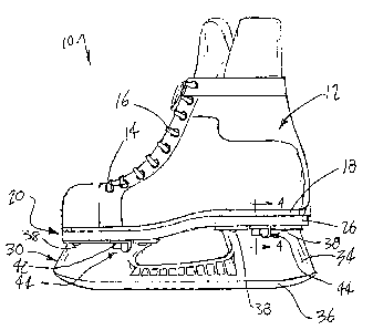
As shown in Figure 1, the skate 10 includes a
shoe body 12 of conventional construction. The shoe body
12 may be formed of any suitable shoe material, such as
leather, rigid or soft plastic, or combinations thereof.
A plurality of apertures 14 are provided on the shoe body
12 for receiving conventional laces 16. Other shoe
securing means, such as clasps, etc., may also be
employed on the shoe body 12.
In the embodiment shown in Figure 1, the shoe
body 12 has a sole 18 integrally formed therewith or
attached to a bottom portion of the shoe body 12 in a
conventional manner. The sole 18 may be formed of any
suitable material, such as leather, plastic, etc.
According to the present invention, the
convertible skate 10 includes an adapter means 20
generally in the form of a plate which is shown in
greater detail, in Figure 2. The adapter means, hereafter
referred to simply as the adapter plate 20, may be formed
of any suitable material, such as metal, plastic, etc.
However, plastic is preferred due to its light weight.
2167102
9
Although the adapter plate 20 may have a generally planar
form from a toe end to a heel end, preferably, the toe
and heel ends are vertically offset, as shown in Figure
1, as found in a normal shoe or boot. The adapter plate
20 is secured to the sole 18 of the shoe body 12 by means
of suitable fastening means which may include the use of
adhesives as well as various fasteners, such as screws,
rivets, etc., which extend through apertures 22 formed in
the adapter plate 20 into the sole 18.
Generally, the adapter plate 20 includes a
central portion 24 which has an exterior shape matching
that of the sole 18. A sidewall 26 depends from the
central portion 24 and forms a recessed cavity between
the interior confines of the peripheral sidewall 26 and
the central portion 24. The peripheral sidewall 26 is
preferably disposed at an obtuse angle so as to extend
angularly outwardly from normal to the plane o~ the
central portion 18 as shown in Figure 4. By way of
example only, the peripheral sidewall 26 is disposed at a
1°-3° angle from normal to the central portion 24.
An attachment denoted generally by reference
number 30, as shown in Figure 1 and in greater detail in
Figures 3, 4 and 5, is detachably mountable in the
adapter plate 20. Preferably, the attachment 30 is one
of a plurality of distinct attachments, others of which
are described in greater detail hereafter.
The attachment 30 includes an attachment plate
32 which has an overall size and shape so as to fit in
substantial registry in the internal recess in the
adapter plate 20 in tight, non-movable engagement with
the central portion 24 and the sidewall 26 of the adapter
plate 20. The peripheral edge 33 of the attachment plate
32 is formed at an angle with respect to the plane of the
attachment, plate 32 which is complimentary to the obtuse
angle of the peripheral sidewall 26 of the adapter plate
20, i.e. 1°-3° in the noted example. A support or
housing 34, which carries an ice blade 36 in the
2167102
embodiment shown in Figures 1, 3 and 5 is mounted on the
attachment plate 32. The support 34 is typically formed
of a molded plastic, although metal may also be use, and
is secured at an upper end to the attachment plate 32 by
5 means of fasteners, such as screws 38, which extend
through an upper mounting portion of the support 34
through apertures 40 in the attachment plate 32 to
securely connect the support 34 and the ice blade 36 to
the attachment plate 32.
10 According to the present invention, means are
provided for releasably attaching the attachment plate 32
of the attachment 30 to the adapter plate 20. In one
embodiment shown in Figures 1-5, the attaching means
preferably comprises fastener means 42 depending from the
adapter plate 20. Preferably, the fastener means 42
comprises a threaded Allen head screw which extends
through the apertures 40 in the attachment plate 32 as
well as through the apertures 22 in the central portion
24 of the adapter plate 20 into the sole 18 of the shoe
body 12 to also serve to securely mount the adapter plate
20 to the sole 18 of the shoe body 12. A cam means
denoted generally by reference number 44 is movably
mounted about the threaded shank of each screw 42. The
cam means 44 includes a hollow base 46 rotatably disposed
about the shank of the screw 42 and an enlarged wing or
pad 48 integrally formed with and extending outward from
the base 46. As shown in Figures 2 and 4, the pad 48 is
disposed adjacent to the head of the fastener 42 and is
rotatable thereabout. The screws 42 may be tightened so
as to lock the fastener 44 and the pad 48 in a fixed
position as described hereafter.
Engagement apertures 50 are formed in the
attachment plate 32. The fasteners 42 on the adapter
plate 20 extend through the apertures 50 in the
attachment plate 32, as shown in Figure 4, to enable the
attachment plate 32 to be mounted on the adapter plate
20.
2167102
Four apertures 50, preferably in the form of
slots extending from an open end on a peripheral edge 33
of the attachment plate 32, are provided by way of
example only. Similarly, four fasteners 42 are mounted
on the adapter plate 20.
In use, the screws 42 are loosened and the pads
48 of the fasteners 44 rotated to an outwardly extending
position from the longitudinal center line of the adapter
plate 20, as shown in phantom in Figure 5. In this
position, the pads 48 are in alignment with the
longitudinal open extent of the slots 50 and permit the
attachment plate 32 to be inserted into the recess in the
adapter plate 20, with the apertures 50 passing over the
pads 48 and the heads of the screws 42. The pads 48 are
then rotated inward to the position shown in solid in
Figure 5. In this position, an inner surface 52 of the
each pad 48 engages the surface of the attachment plate
32 in a caroming action to force and retain the. attachment
plate 32 in secure, non-movable engagement with the
adapter plate 20. The screws 42 may then be tightened to
lock the pads 48 in a locking position to securely retain
the attachment 30 in the adapter plate 20.
The sequence is reversed to release the
attachment 30 including the attachment plate 32 from the
adapter plate 20.
As shown in Figure 4, when the attachment plate
32 is mounted in the adapter plate 20, in substantial
registry with the central portion 24 of the adapter plate
20, the angularly disposed peripheral edge 33 of the
attachment plate 32 engages the angularly disposed inner
surface of the depending sidewall 26 of the adapter plate
20 in a tight, non-movable fit. This prevents any
movement of the attachment plate 32 relative to the
adapter plate 20 in either longitudinal or lateral
directions thereby providing a secure, non-movable
mounting of the attachment 30 to the adapter plate 20.
2167102
12
A different attachment 60, shown in Figure 6,
is also releasably mountable in the adapter plate 20 on
the shoe body 12. The attachment 60 includes an in-line
roller assembly denoted generally by reference number 62
which is secured at an upper portion to the attachment
plate 32 by means of fasteners extending through the
apertures 40 in the attachment plate 32. As shown in
Figure 6, the attachment plate 32 is also provided with a
plurality of apertures 50, preferably in the form of
l0 open-ended slots extending inward from the peripheral
edge 33 of the attachment plate 32.
The in-line roller assembly 62 may be of any
conventional construction and includes a plurality of
pairs.of depending, spaced legs 64, each of which
receives an axle 66 therethrough for rotatably mounting a
roller 68 thereon. The attachment 60 is detachably
mounted in the adapter plate 20 in the same manner as the
attachment 30 described above.
It should further be noted that the attachments
30 and 60 are provided with identical heights from a
lower ground or ice engaging surface of the blade 36 in
the attachment 30 or the rollers 68 in the attachment 60
with respect to the upper surface of the attachment plate
32. In this manner, regardless of which attachment 30 or
60 is mounted on the shoe body 12, the height of the shoe
body 12 with respect to an underlying surface is the
same.
Yet another attachment 70, shown in Figure 7,
is also releasably mountable in the adapter plate 20 on
the shoe body 12. The attachment 70 also includes an
attachment plate 32 having a plurality of apertures 50,
such as open-ended slots, formed therein.
A conventional shoe sole 72 is attached to the
adapter plate 32 in the attachment 70 by means of
suitable fasteners extending through the sole 72 through
the apertures 40 in the attachment plate 32. The sole 72
may be formed of any suitable material, such as a molded
2167102
13
rubber or plastic, by way of example only. It should be
noted that in the attachment 70, as well as in the
previously described attachments 30 and 60, slots are
formed in the sole 72 in line with the slots 50 in the
attachment plate 32 to pass over the fasteners 42 on the
adapter plate 20 when the attachment plate 32 is inserted
in or removed from the adapter plate 20.
Another embodiment of the convertible skate 10
of the present invention is shown in Figure 8. This
embodiment, which is usable with any of the attachments
30, 60 or 70 includes an adapter plate 80 having
substantially the same construction as the adapter plate
described above and shown in Figures 1 and 2.
However, in this embodiment, the adapter plate 80 forms
15 the sole of the shoe body 12. Preferably, the adapter
plate 80 is formed of a plastic material and is
integrally molded as a unitary one-piece part of the shoe
body 12. The adapter plate 80 also includes a central
portion 82 and a depending peripheral sidewall 84
20 disposed at an obtuse angle with respect to the central
portion 82 as in the adapter plate 20 described above.
In this embodiment, the means for attaching the
various attachments to the adapter plate 80 incudes a
plurality, such as four by way of example only, of
inserts 86 which are located about the periphery of the
central portion 82 of the adapter plate 80. The inserts
86 are of conventional construction and are formed of a
molded plastic body 88 having a through bore extending
therethrough. A metallic sleeve 90 is press fit or
otherwise fixedly mounted in the bore of the housing 88.
The sleeve 90 has an internally threaded throughbore 92
formed therein.
The sleeves 90 threadingly receive fasteners
94, such as a flat head Allen screw or an Allen head cap
screw, which extend through apertures 96 formed in the
attachment plate 32 of any of the attachments 30, 60 or
70 described above to releasably mount the attachment
2167102
14
plate 32 and the attachment mounted thereon to the
adapter plate 80. It will also be understood that the
cam-type fastener 44 described above and shown in detail
in Figure 4 can also be employed with the adapter plate
80 shown in Figure 8.
Figures 9-16 depict other embodiments of the
present invention. Components shown in Figures 9-15
which correspond to like components shown in Figures 1-8
are indicated by the same reference number.
In this embodiment, an adapter plate 100 is
integrally formed, such as by unitary molding, with the
bottom portion of the shoe to form a one piece member as
shown in Figures 9 and 10. In such an integral, one
piece, molded construction, the adapter plate 100
actually forms the sole of the skate body. Accordingly,
the adapter plate 100 is formed of a suitable high
strength moldable material, such as plastic. As in the
first embodiment, the adapter plate 100 includes a
peripheral sidewall 102 depending from a central portion
104.
In this embodiment, a backing member 106 is
mounted within the adapter plate 100 and forms a portion
of a fastener receiving means. The backing member 106 is
preferably integrally molded in the adapter plate 100;
although fasteners may also be employed for mounting.
One embodiment of the backing member 106 is shown in
Figures 10 and il. In this embodiment, the backing
member 106 is in the form of an elongated metallic strip
having an enlarged first end 108 in which a pair of
spaced through apertures 110 are formed. A fastener
receiving means such as a threaded member 112, i.e. a
nut, having an internally threaded bore is fixed, such as
by welding, on the enlarged first end 108, with the bore
in the nut 112, aligned with the apertures 110 in the
backing member 106.
The forward or toe end of the reinforcing
member 106 is provided with a cup-shaped member 114 which
2167102
extends externally of the adapter plate 100 and below the
edge of the sidewall 102. The cup-shaped member 114 has
a generally semi-circular shape to define a hollow
receptacle which engages the toe end of the attachment
5 plate and aids in resulting lateral and longitudinal
movement of the attachment relative to the adapter plate
100.
An alternate embodiment of the backing member
is shown in figure 12. In this embodiment, a small plate
10 120 is mounted on the adapter plate 100 by means of
fasteners or by integral molding and has a pair of
apertures 122 aligned with threaded nuts 112 welded on
the plate 120. Intermediate outwardly extending flanges
124 are formed on the plate 120 for receiving mounting
15 fasteners to fixedly attach the plate 120 to the adapter
plate 100. In this embodiment, the cup-shaped member 114
is mounted to a separate plate 126 also attached to or
integrally molded in the adapter plate 100 by.,means of
fasteners.
Yet another embodiment of the backing member is
shown in Figure 13. In this embodiment, the cup-shaped
member 114 is also formed as a part of a separate plate
126 attached to or integrally molded in the toe end of
the adapter plate 100. A pair of threaded inserts 128,
similar to the inserts 86 described above and shown in
Figure 8, are mounted in or integrally molded in the
adapter plate 100, with the threaded bore with the
inserts 128 aligned with apertures formed in the adapter
plate 100.
Referring again to Figures 9 and 10, one
embodiment of an attachment 130 is depicted for
releasable engagement with the adapter plate 100. In
this embodiment, the attachment 130 is in the form of an
ice blade.having a blade 36 and a support housing 34,
typically formed of a molded plastic. Although the
support housing 34 may be integrally formed with an
attachment plate 132, as described in another embodiment
2167102
16
hereafter, in this embodiment, the support housing 34 is
formed with toe and heel mounting flanges 134 and 136,
respectively, which extend outward from the main body of
the support housing 34. Apertures are formed in the
flanges 134 and 136 and are aligned with correspondingly
formed apertures formed in the attachment plate 132 to
receive suitable fasteners 138, such as Allen head cap
screws. It should be noted that the arrangement of the
apertures correspond to a conventional international
mounting hole pattern used in professional hockey skates.
The fasteners 138 provide secure, yet releasable
engagement of the attachment 130 to the attachment plate
132.
Fastener means denoted generally by reference
number 140 is mounted on the attachment plate 132 and
releasably engage the fastener receiving means 112 in the
adapter plate 100. Preferably two fastener means 140 are
mounted substantially centrally between the toe and heel
of the attachment plate 132 and are laterally spaced ,
apart as shown in Figure 15. As shown in Figures 9 and
10, and in greater detail in Figures 14 and 15, each
fastener means 140 is formed of a shaft member 142 having
opposed first and second threaded ends 144 and 146,
respectively. An enlarged frustoconical shaped surface
148 is formed on the shaft 142 intermediate the first and
second ends 144 and 146. A generally cylindrical shaft
portion 150 is located between one end of the conical
surface 148 and the second end 146.
The first threaded end 144 of the shaft 142
threadingly engages the fastener receiving means 112 and
the apertures in the adapter plate 100 as shown in Figure
15. During such mounting, the frustoconical surface 148
engages a complimentary formed conical bore 150 formed in
the attachment plate 132. The use of mating conical
surfaces provides secure attachment of the attachment
plate 132 to the adapter plate 110 and minimizes any
2167102
17
lateral and longitudinal movement of the attachment plate
132 relative to the adapter plate 110.
Each fastener means 140 also include a mount
152 having a depending, cup-shaped central portion 154
with a central aperture 156 formed therethrough. A pair
of oppositely extending mounting flanges 158 extend from
the cup-shaped portion 156 and each has an aperture 160
formed therein for receiving a suitable mounting fastener
162 to attach the mount 152 to the attachment plate 132.
In use, the mount 152 is affixed to the
attachment plate 132 as shown in Figure 15 by means of
the fasteners 162. In this mounting position, the shaft
142 is held captive within the mount 152 yet is capable
of a slight amount of movement relative to the attachment
plate I32.
A user engagable member 164 generally in the
form of a planar disk having a central aperture 166 and a
serrated peripheral edge 168 is mounted on the.second end
146 of the shaft 142 and provides a suitable user ,
engagable surface for threadingly engaging the shaft 142
with the fastener receiving means 112 in the adapter
plate 110 as well as enabling release of the attachment
plate 132 from the adapter 110. This eliminates the need
for a separate tool to attach and detach the attachment
130 to and from the adapter plate 110. Alternately, a
nut 170 may be mounted about the exterior end of the
second 146 of the shaft 142 adjacent to the disc 164 to
permit the use of wrench to provide secure tightening or
release of the fastener 140 to the adapter plate 110.
Figure 16 depicts another embodiment of the
present invention in which an attachment plate 176,
substantially identical to the attachment plate 132
described above and shown in Figure 15, has a integrally
molded in-line housing 178 extending from one surface
thereof. One or more fasteners 140 are mounted on the
attachment plate 176 in the same manner as described
above and shown in Figure 15.
2167102
18
The housing 178 includes a pair of spaced side
legs which are integrally joined to the attachment plate
176 at an upper end. The opposite ends of the support
legs 180 are spaced apart and receive a plurality of
axles 182, each supporting a roller 184, as is
conventional in the construction of in-line roller
skates. The attachment and detachment of the housing 178
and the attachment plate 176 to the adapter plate 110 is
the same as that described above for the other
embodiments of the present invention.
The attachment plate 132 may also have a shoe
sole, similar to sole 72 shown in Figure 7 fixedly
attached to or integrally molded thereto. Additional
attachments, such as various skate blades including speed
skate blades and figure skate blades, as well as snow
shoes, ice claws, etc., may also be mounted on or
integrally molded to one of the attachment plates
described above.
Refer now to Figs. 17 and 18, another ,
embodiment of the present invention is depicted which
includes unique lateral support means. Generally, the
lateral support means is mounted on one of the adapter
plate 100 or the attachment plate 132 of the convertible
skate of the present invention. In addition, lateral
support engaging means is mounted on the other adapter
plate 100 and the attachment plate 132 for securely
receiving the lateral support means when the attachment
130' is mounted in the adapter plate 100.
In a preferred embodiment, the lateral support
means is in the form of two pairs of spaced projections
or ribs 200 and 202 which are formed on and extend
outward from the attachment plate 132. Each pair of ribs
200 and 202 includes two ribs which are disposed on
opposite sides of the longitudinal center line of the
attachment plate 132 and the underlying use element, such
as the ice blade 36 or of rollers of an in-line roller
skate assembly. Further, the pair of ribs 200 are
2167102
19
disposed at the toe portion of the skate; which the pair
of ribs 202 are disposed at the heel section of the
skate.
As shown more clearly in Fig. 19, the ribs 200
and 202 have a generally rectangular cross section;
although other shapes, such as any polygonal shape, or
arcuate shaped elements may also be employed.
In addition, in the situation where the
attachment plate 132 is formed of a metallic material,
the ribs 200 and 202 may also be formed of a suitable
metal and secured in any of a number of suitable methods,
such as welding, etc., to the attachment plate 132. If
the attachment plate 132 is formed of a plastic, the ribs
200 and 202 may be integrally molded as a unitary, one
piece part of the attachment plate 132.
Further, although Fig. 17 depicts the lateral
support ribs 200 and 202 as used on an ice blade assembly
130.', it will be understood that such lateral.support
ribs 200 and 202 may also be employed on an in-life .
roller assembly 178 shown in Fig. 16 and described above.
Although two pairs of spaced ribs 200 and 202
are described as forming the lateral support means of the
present invention, it will be understood that other
support rib configurations may also be employed within
the scope of the present invention. For example, a
single elongated rib may extend along the longitudinal
center line of the attachment plate 132. In addition, a
single pair of ribs in which each rib is formed as a
single elongated rib extending along the peripheral edge
of the adapter plate 132 may also be provided.
As shown in Figs. 17 and 18, the support
engaging means is preferably in the form of apertures 204
and 206 which have a complimentary shape to the ribs 200
and 202. ,Thus, a pair of ribs 204 are disposed at the
toe section of the adapter plate 100 and a second pair of
ribs 206 are formed at the heel portion of the adapter
plate 100. The pairs of apertures 204 and 206 are
2167102
preferably in the form of elongated slots which extend at
least partially or even completely through the adapter
plate 100. The apertures 204 and 206 are sized to
snugly, but releasably receive the ribs 200 and 202 when
5 the attachment plate 132 is mounted in the adapter plate
100.
It will be understood that although the ribs
200 and 202 have been described and illustrated as being
mounted on the attachment plate 132 and the complementary
10 shaped slots 204 and 206 formed in the adapter plate 100,
an opposite mounting position in which the ribs 200 and
202 are formed on and extend outward from the central
portion 104 of the adapter plate 100 and engage
complimentary shaped apertures 204 and 206 formed in the
15 attachment plate 132 is also possible according to the
present invention.
Fig. 19 depicts the use of the lateral support
ribs 200 and 202 on a conventional ice blade attachment
130. The attachment 130, as described above, is affixed
20 to a conventional skate shoe sole by means of fasteners,
such as rivets, not shown, which extend through apertures
in the toe and heel plates 134 and 136 of the attachment
130 into correspondingly positioned apertures in the
skate shoe sole. In this arrangement, the pairs of ribs
200 and 202 extend outward from the toe and heel portions
134 and 136, respectively, and engage complementarily
shaped apertures, such as elongated slots, formed in the
shoe sole. Contrary wise, the pairs of ribs 200 and 202
may be mounted or formed on and extend outward from the
shoe sole to engage complementarily shaped apertures
formed in the toe and heel portions 134 and 136 of the
skate attachment 130.
The use of the pairs of ribs 200 and 202 and
the complementarily shaped apertures 204 and 206 on the
skate shoe sole and use attachments, according to the
present invention, uniquely isolates high torque forces
generated during normal use of a skate from the rivets or
2167102
21
other fasteners normally used to mount the use attachment
on the shoe sole. Since the fasteners are isolated from
such torque forces, potential damage to or breakage of
the fasteners is minimized thereby prolonging the useful
life of the fasteners with minimal repair time.
In summary, the lateral support ribs of the
present invention uniquely isolate lateral torque force
from the fasteners used to attach an ice blade or in-line
roller assembly to a skate boot. The ribs and the
complementary apertures which engage the ribs are formed
on the boot sole and the blade or roller assembly
housing. The support ribs are also useable in a
convertible skate assembly.