Note : Les descriptions sont présentées dans la langue officielle dans laquelle elles ont été soumises.
CA 02168486 1999-03-22
PARTICLE AGGLOMERATION AND
PRECIPITATION FROM A GASEOUS STREAM
Field of the Invention
This invention relates both to improvements in particle
precipitators and to particle agglomerators designed for use with
particle precipitators, as well as to the combination of a
particle agglomerator and a particle precipitator. The invention
has both method and apparatus aspects.
Backaround of the Invention
It is known in the prior art to use a particle precipitator
for separating entrained particles from a turbulent gaseous flow
(commonly, but not necessarily, air). The particles may be solid
or liquid.
In the specific description below, one aspect of the present
invention will be explained mainly in relation to the separation
from a turbulent air stream of an oil mist, i.e. ultra-fine
suspended oil particles, typically droplets of the order of less
than 0.5 microns. Such a mist-laden air stream is typically
encountered as exhaust: from industrial machinery operating at
high speed.
It should be understood, however, that this exemplifi-
cation of the present invention in relation to the separation of
oil droplets from an air stream is not intended to be limiting to
the broad scope of the present invention, since the invention is
also applicable to the separation (precipitation) of other
suspended liquid or solid particles, e.g. dust, fumes or smoke.
Such separation can be carried out by any form of precipitator,
such as an electrostatic precipitator, that is capable of
carrying out the desired separation of particles from a gaseous
stream.
It has been found that the efficiency of a particle
precipitator is significantly greater if the particles are of a
-1-
CA 02168486 2000-06-07
certain minimum size. The separation of submicron particles by
a precipitator is less efficient or may require more expensive
equipment. For example, adequate separation of submicron
particles may require a multiple stage or unduly long
precipitator. Hence, either an unsatisfactory result or a need
for unduly expensive equipment will be experienced.
Summary of the Invention
An object of the present invention is to avoid these
difficulties by providing a method and apparatus for
increasing the size of the particles in the gaseous stream and
then precipitating these increased size particles from the
gaseous stream.
In accordance with one aspect of the present invention
there is provided an agglomeration and precipitation device
comprising in combination: (a) an agglomeration device
intended to receive a turbulent gas stream containing fine
suspended particles and to discharge the stream in which the
major part of said fine particles has agglomerated in the form
of larger particles, and (b) a precipitation device provided
downstream of the agglomeration device to receive the stream
coming from the agglomeration device and to separate the
larger particles from the gas stream, wherein said
precipitation device comprises at least one non-obstructed
channel intended to convey the stream exhibiting a turbulent
flow and a series of objects extending along at least one side
of each channel, said objects being positioned at close
intervals in the direction of flow so as to define with each
other spaces which swirls coming from each channel enter,
which leads to an accumulation of particles at the surface of
said objects after the swirl have declined, wherein said
-2-
CA 02168486 2000-06-07
objects consist of at least one corrugated plate.
The agglomerator of this combination may comprise a duct
with a mouth for receiving the stream and an exit for
discharging the stream, and a series of screens mounted
substantially parallel to each other in the duct while spaced
apart along the duct between the mouth and the exit, each
screen extending across the duct generally transversely of the
stream so that substantially the entire stream passes through
all the screens successively. Each screen has solid portions
distributed across the duct for impaction by some of said
particles and holes distributed across the duct for unhindered
passage of the stream. The agglomerator will preferrably also
contain some means for discharging the agglomerated particles
that are not re-entrained into the gas stream, but fall to the
bottom of the unit.
In accordance with another aspect of the present
invention there is provided a method of agglomerating and
precipitating particles suspended in a gas stream exhibiting
turbulent flow having a direction of flow, said method
comprising the steps of: (a) agglomerating, in an
agglomerating portion of a device, fine particles in a
turbulent gas stream, containing said fine particles in a
suspended form, wherein a major number of said fine particles
are formed into larger particles; (b) discharging said larger
particles from said agglomerating portion of said device; (c)
inputting said larger particles and said gas stream into a
precipitation portion of said device; (d) separating, by
precipitation, said larger particles from said gas stream,
said separating step comprises the steps of: (e) flowing said
larger particles and said turbulent gas stream through at
least one non-obstructed channel intended to convey the gas
-3-
CA 02168486 2000-06-07
stream exhibiting turbulent flow and a series of objects
extending along at least one side of each of said at least one
non-obstructed channel, said objects being positioned at close
intervals in the direction of flow so as to define with each
other spaces; and (f) generating swirls in said gas stream in
said spaces, which leads to an accumulation of said larger
particles at surfaces of said objects after the swirl have
declined, wherein said objects consist of at least one
corrugated plate.
-3a-
CA 02168486 1999-03-22
collection of the particles on surfaces of said objects upon
decay of the eddies. According to a further aspect of the
present invention, the objects on the surfaces of which the
particles collect are formed from at least one pleated sheet.
Brief Description of the Drawings
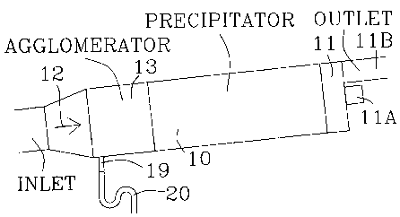
Figure 1 shows an overall arrangement of an agglomerator and
a precipitator;
Figure 2 shows a fragmentary, cut-away, side view of an
agglomerator according to an embodiment of the present invention,
such agglomerator being adapted to be mounted at the input end of
a particle precipitator;
Figure 3 is a fragmentary, cut-away, plan view of part of
the agglomerator of Figure 2;
Figure 4 is a view taken on the line 4-4 in Figure 2;
Figure 4A shows a fragment of a variant of Figure 4;
Figure 5 is a fragmentary, cut-away, perspective view of a
collector element in a modified form of precipitator according to
another embodiment of the invention;
Figure 6 is a cut-away, end view of the precipitator of
Figure 5;
Figure 7 is a cut-away, underside view of the precipitator
of Figures 5 and 6; and
Figure 8 is an enlarged fragment of a collector element in
this precipitator.
Detailed Description of the Preferred Embodiments
The particle precipitator 10 shown in Figures 1 and 2 may be
the particle precipitator described below with reference to
Figures 5 to 8. Alternatively, it may be any other precipitator
capable of separating solid or liquid particles from a turbulent
air stream 12 sucked into the system by a fan 11 or by any other
means. The fan has a motor 11A and an outlet 11B.
-4-
CA 02168486 1999-03-22
In advance of the precipitator 10 there is located an
agglomerator 13, the function of which is to increase the size of
the particles entrained or suspended in the air stream 12, so
that collector surfaces of the precipitator 10 can perform more
effectively in separating them from the stream.
The system shown in Figure 1 is assumed to be designed for
the separation of liquid particles from the gaseous stream, e.g.
from a mist, for which reason it is inclined to the horizontal
and is fitted with a liquid trap 20. The liquid collected in the
system (mainly, but not exclusively, in the bottom of the
precipitator) flows down on the bottoms of both the precipitator
and the agglomerator, to enter the drain 19 and hence the trap 20
which serves as an external collector for the liquid while
preventing air from being sucked into the system at this
location. Typical liquid levels in the drain 19 and trap 20 are
shown.
When the system is designed for separating solid particles,
e.g. dust, these latter features are modified, as is explained
below in relation to figures 6 and 7.
As shown in Figures 2 and 3, the agglomerator 13 may consist
of a tubular duct 14 of rectangular cross-section (specifically,
in an example, 34 cm long, 46 cm wide and
cm high) forming a tunnel between a mouth connected to the
inlet for the gaseous stream and an exit connected to the
25 precipitator 10. Situated in this duct 14 is a spaced apart
series of screens 15, each of which extends fully across the duct
in both directions perpendicular to the air stream 12 so that
substantially all the air stream must pass successively through
all these screens. In practice, a small amount of the stream may
30 pass around the edge of the screens.
As shown in Figure 4, which is not to scale, a typical
screen 15 consists of two sets of transverse strands 16 forming a
mesh, the strands being made of an appropriate material, such as
_5_
CA 02168486 1999-03-22
polyester, fiberglass or metal. In a typical example each strand
16 is approximately 1 mm thick, the strands being spaced apart
from each other by approximately 5 mm. The ratio of the spacing
between the strands to the thickness of the strands can be in the
range of ten to five. A convenient method of forming this
assembly when the screens 15 are made of a flexible material is
to employ a very long strip of such material and thread it over
top and bottom rods 17 and 18 that extend across the duct 14.
The diameter of these rods will determine the spacing between the
individual screens 15, which spacing can conveniently be within
the range of approximately 5 mm to
1 cm. If the screens are placed much closer together than this,
their function, as explained below, will not be fully achieved,
since they will not act fully as separate screens. If they are
placed further apart, while they will function effectively, they
will cause the apparatus to be unnecessarily long.
With the turbulent air stream 12 assumed to be carrying
submicron oil mist particles entering the mouth of the
agglomerator 13, it has been found experimentally that a few of
the particles will separate from those portions of the air stream
that pass on each side of each strand 16, such separated
particles impacting directly on the strands. At each screen 15
only a small fraction of the incoming mist particles will impact
on the strands, because most of the particles will pass
unhindered with the air stream through the holes between the
strands. Assuming that a fraction y of the incoming mist
particles impacts on the solid portions (strands) of the first
screen, the remaining fraction (1 - y) will pass through the
holes. Turbulence will mix the mist particles that have passed
with the stream through the holes to a substantially uniform
distribution before they reach the second screen. Additionally,
if found useful, the strands can be staggered between adjacent
screens to ensure that there are strands located directly in the
-6-
CA 02168486 1999-03-22
path of the particles that have passed with the stream through
the holes of the previous screen. At the second screen the same
fraction y of the remaining fraction (1 - y) will impact on the
strands. The fraction remaining (transmitted through the holes)
after the second screen is thus (1 - y) - y(1 - y) - (1 - y)2.
After passing through n screens the fraction of the original oil
mist particles remaining in the air stream will be (1 - y)n. A
typical value for y will be 0.04, i.e. 40. If n = 60, for
example, the fraction of particles remaining after the stream has
passed through the last screen of the series will be 0.96 to the
power 60, which is approximately 0.09. Thus, a fraction of about
9% of the original mist particles will remain in the air stream
exiting the agglomerator, while about 91% will have impacted on
one or other of the screens.
After impaction, most of the impacted particle material
tends to become re-entrained in the air stream. However, it has
been found that this re-entrained material consists of new
particles that are larger than the original particles. In other
words, the original individual fine particles have become
agglomerated into larger particles. Some of these agglomerated
particles remain in the agglomerator by falling to the floor of
the unit, forming a bulk liquid that flows into the trap 20 to
form part of the total collected particles. An important
consideration for this function to occur is that the gaseous
stream passing through the agglomerator should be in turbulent
flow.
In an experiment conducted with an oil mist generated by a
nebulizer, it was measured that about 80o by weight of the mist
particles entering the agglomerator were smaller than 0.5
microns. When this mist was passed directly into a precipi-
tator that was one meter long (with the agglomerator removed),
only about 40% by weight of the particles were separated from the
air stream. However, when the agglomerator was located between
CA 02168486 1999-03-22
the incoming mist and the same precipitator, the latter separated
approximately 93% by weight of the mist particles from the air
stream. Theory predicts that this same stream performance (93%
collection) could have been achieved by a precipitator alone
(without the agglomerator), if the length of the precipitator had
been increased to five meters. While the agglomerator alone is a
very poor collector of submicron particles, the synergistic
combination of the phenomena taking place in the agglomerator and
the precipitator acting together provides a method of achieving
the desired high performance in separating fine particles without
the need to use a longer precipitator.
To demonstrate this synergism, assume the particle
agglomerator collected the mist with an overall fractional
efficiency a and the precipitator collected the same mist with an
overall fractional efficiency b. Then, in the absence of
synergism, the fractional efficiency E of the combined system
agglomerator plus precipitator would be E = 1-(1 - a)(1 - b). As
has been shown, the actual fractional efficiency E' of the
combined system agglomerator plus precipitator is much greater
than E, i.e. E' »E. Not only does this show the existence of
synergism, but it also shows the physical reason for it, which is
that the mist leaving the agglomerator and entering the
precipitator is not the same mist as entered the agglomerator,
but it is a much greater particle size mist, which is recovered
with a much higher fractional efficiency b'>b by the precipitator
than the original mist would have been. Hence
1-(1 - a)(1 - b') » 1-(1 - a)(1 - b). The particle size
distribution of the original mist has been determined to be 80%
by weight under 0.5 micron, whereas the mist leaving the
agglomerator has a mean particle size of about 4 micron. The
measured efficiencies involved are E' - 0.93, b' - 0.9,
b = 0.4, and a = 0.3, whence E = 0.58. It is thus evident that
E' »E .
-g-
CA 02168486 1999-03-22
In the mathematical examples above it was assumed that 60
screens were used, and in the actual experiment referred to above
57 screens were used. The choice of the number of screens will
be a compromise between improved performance (more screens) and
economy (fewer screens). In a case where some loss of
performance is tolerable, or, if the size of the incoming
particles is larger than submicron but nevertheless fine in the
sense of being undesirably small for separation directly by the
precipitator, a smaller number of screens can be used. The
number of screens will preferably not normally be less than 30,
but even this number may go as low as ten or even lower when
either a lesser performance is acceptable or the value of y can
be increased, or the apparatus is dealing with a mist containing
significantly larger initial droplets. Thus there can be
circumstances in which only a relatively small number of screens
would be useful. There is really no maximum, although anything
over 100 would normally be uneconomical in relation to the
advantage gained. The preferred range will normally be 30 to 80.
While each screen 15 has so far been described as being in
the form of a meshlike structure formed of mutually perpendicular
strands, it is also possible to employ any other structure, such
as a plate with holes punched in it, that achieves the same
effect, namely provides a large number of distributed solid
portions for impaction of some of the particles, while leaving
holes for the gaseous stream and the remaining particles
entrained therein to pass through. While the use of a plate with
punched holes may increase the pressure loss experienced by the
gaseous stream, it may, on the other hand, increase the value of
y and hence reduce the number of screens needed, which in turn
will have a desirable effect on the pressure drop.
It is to be understood that the reference to "screens" in
the appended claims is intended to include not only meshlike
structures but also non-meshlike structures, such as a punched
_g_
CA 02168486 1999-03-22
plate 16A shown in Figure 4A, provided that the alternative
serves a like purpose of providing a distributed area of solid
portions for the particles to impact against and open spaces for
the gaseous stream to pass through unhindered. In the interest
of minimizing the pressure drop, the area of the solid portions
will normally be a portion less than 50% of the total cross
section of the duct.
Several long-term tests have been run with an oil mist
input. At the end of these tests the screens in the
agglomerator, as well as the particle collector elements in the
precipitator, were found to be soaked with oil. The flow rate
used was 1000 cubic meters per hour, and the air stream velocity
was seven meters per second. Very satisfactory separation of the
oil droplets was obtained with an acceptable pressure loss of
only five centimetres of water column.
The screens will preferably be oriented generally
vertically, with the gaseous stream flowing generally
horizontally. However, these requirements are not rigid and some
deviation from them will still allow the agglomerator to function
effectively. Indeed, the tilting of the system to provide for
run off of the collected liquid into the trap 20 will represent
some deviation from a truly horizontal orientation, and, as
indicated below, the degree of tilt may be increased, e.g. 15°,
when solid particles are being collected. Normally, there would
be no advantage in varying from a gaseous stream that flows
generally horizontally and screens that are mounted generally
vertically.
Figures 5 to 8 show details of those aspects of a
precipitator that represent variations on the constructions
disclosed in the prior art. The theory underlying the particle
separating performance of the precipitator of Figures 5 to 8
nevertheless remains essentially the same as that set out the
prior art.
-10-
CA 02168486 1999-03-22
In Figures 5 to 8 the precipitator 10 has a casing 21,
forming a tunnel extending from a mouth that receives the gaseous
stream from the agglomerator or directly from an intake if no
agglomerator is necessary because of the relatively large size of
the entrained particles, to an exit connected to the fan.
In order to provide as extensive a disclosure as possible
the precipitator of Figures 5 to 8 is shown as one designed for
the separation of solid particles, without an agglomerator
attached to it. The basic construction is nevertheless equally
applicable to the separation of liquid particles, subject only to
the adoption of a suitable liquid collecting arrangement, such as
the discharge channels and trap 20, to replace the dust
collecting arrangement shown in Figures 5
to 8.
The collector elements that extend along the casing 21 take
the form of pleated sheets 22, preferably of metal. The pleated
sheets 22 extend all the way from the top of casing 21 to within
a short distance from the bottom of the casing, leaving a
clearance through which the collected dust can pass through
opening 30 and slot 25 into the hopper 26. In Figure 5 only the
beginning of one pleated sheet 22 is shown for simplicity. There
will in practice be a plurality of such sheets side by side, e.g.
the three shown in Figures 6 and 7, positioned across the casing
21 while spaced apart to allow channels 23 for the gaseous stream
located between adjacent sheets and between the sheets and the
casing. Since this embodiment of the invention is designed for
collecting dust and dust does not flow as readily as a liquid,
the casing 21 is given an increased tilt, e.g. at least 15°, to
the horizontal 29, and a vibrator 28 is connected to it to make
the dust flow down its floor. When the dust that has been
collected by the pleated sheets 22 falls to the bottom of the
casing 21, some of it would spread out into the open channels 23
if not restrained, and would be subject to re-entrainment in the
-11-
CA 02168486 1999-03-22
gaseous stream. To avoid this result the bottoms of the sheets
22 are enclosed within troughs 24. At the lower (input) end of
the casing 21, these troughs 24 have opening 30 communicating
with a slot 25 that extends across the casing floor and
communicates with a hopper 26 (omitted from Figure 5 for
simplicity) that acts as an external collector for receiving the
dust and conveying it away. If an agglomerator is used, it may
conveniently be housed in the same casing 21, or a casing of the
same cross section as 21, as in the case of mist collection shown
in Fig. 1. In this case at the inlet end of the agglomerator
there is a slot 25 rather than a hole to discharge the dust. In
the case of dust collection there is also a clearance left
between the screens and the floor of the agglomerator. A baffle
27 is located at the upper (output) end of the casing 21 to cause
the gaseous stream to exit from the casing at a level above its
floor and hence minimize any tendency to re-entrain dust that has
fallen to the floor.
To minimize the re-entrainment of dust particles that have
been separated from the stream by the pleated sheets, but have
not yet fallen into the troughs, the pleating should be tight,
i.e. should be at a small angle. In other words the depth of
each pleat in the direction d (Figure 8) should be substantially
greater than the pitch p. A desirable ratio for d to p would be
about four. While this ratio can be varied to suit individual
circumstances, it will be kept appreciably greater than one for
the best performance.
-12-