Note : Les descriptions sont présentées dans la langue officielle dans laquelle elles ont été soumises.
21?'n~~
PATENT APPLICATION
DOCKET ID-4411
Inventors: John V. Hinshaw and Paul E. Schallis
FLOW REGULATION IN GAS CHROMATOGRAPH
This invention relates to gas chromatography and particularly to
a gas chromatographic system with regulation of gas flow.
BACKGROUND OF THE INVENTION
Gas chromatography is essentially a physical method of separation
in which constituents of a test sample in a carrier gas are
adsorbed and desorbed by a stationary phase material in a column.
A pulse of the sample is injected into a steady flow of carrier
gas. At the end of the column the individual components are more
or less separated in time. Detection of the gas provides a time-
scaled pattern which, by calibration or comparison with known
samples, indicates the constituents of the test sample. The main
components of such a system are the column, an injector with a
mixing chamber for introducing the sample into the carrier gas, a
detector at the outer end of the column, gas controls and a
device such as a computer for treating and displaying the output
of the detector. An oven may be used to elevate temperature to
maintain the sample in a volatile state, and to improve the
discrimination of constituents.
In the use of open tube or packed capillary types of columns,
only a small flow of carrier gas with the sample is desired,
whereas it is more accurate and convenient to inject larger
quantities of the sample. Therefore, a small portion of the gas
mixture is bled into the column and the major portion is split
off and vented. Such a system is known as a "split injection"
system. The injector generally contains a septum through which
sample is injected. The mixing chamber usually has an outlet for
1
21~0~~8~
a purge gas that is a portion of the carrier gas passed along the
septum. The purge gas removes vapors emitted from the septum
during operation at elevated temperature, as the vapors otherwise
could contaminate the carrier and its test sample flowing to the
column.
An article "The Effects of Inlet Liner Configuration and Septum
Purge Flow Rate on Discrimination in Splitless Injection" by J.V.
Hinshaw, J. High Resolution Chromatography 16, 247-253 (April
1993) illustrates several techniques for gas regulation. One is
a forward-pressure design in which the carrier gas inlet to the
injector is regulated at constant pressure, with mass flow being
controlled in the outlet line of the split f low. Another is
back-pressure regulated from an outlet line, with mass flow being
controlled in the inlet line to the injector. The septum purge
is effected through a restriction in the outlet line to maintain
small purge flow and a selected pressure in the injector. The
restriction may be fixed, or may be a needle valve for adjusting
flows in other branches.
Pressure regulators used in gas chromatography are generally
known, including older style mechanical devices that utilize
spring loaded diaphragms. In newer systems electronic pressure
sensors control variable restrictors for flow control to regulate
pressure. In gas chromatographs, the pressure typically is
generally detected in or proximate the injector. The restrictor
of the regulator may be downstream in the same line, or in either
of the inlet or split vent lines.
For flow rate controllers, U.S. patent No. 4,096,746 (Wilson et
al), for example, discloses a mechanical flow controller that
contains a diaphragm and a restrictor element in which pressure
differential across the restrictor regulates the diaphragm for
gas floe:. Ir. a.~. electronic system, flew rate is dere~ted by
sensing pressure differential across a restrictor element, and
2
217x08
the sensor controls an electrically variable restrictor.
Heretofore, in current systems, the sensor and restrictor have
been disposed in the same line.
A particularly desirable configuration for gas chromatography is
the forward pressure design in which the carrier gas inlet to the
injector is regulated at constant pressure, with the mass flow
being controlled in the outlet line of the split flow. Benefits
are improved performance and mass flow discrimination as
indicated in the aforementioned article by Hinshaw. However, in
this type of system, a mass flow controller including its sensor
placed in the vent line has not been practical as it does not
function properly in this location. One reason is that the mass
flow sensor has a restrictor that creates a pressure drop
substantially greater than the desired pressure at the outlet
location, so that the back pressure at the injector would be too
high. Another is that pressure drop across the restrictor
(representing flow detection) is nonlinear in the desired low
pressure range of the outlet location, whereas it is essentially
linear at higher pressures. Therefore, flow rate in a forward
pressure regulated system has generally been set manually by use
of a needle valve in the split vent line.
SUMMARY
An object of the invention is to provide an improved gas
chromatographic system having control of flow rate in the split
vent output line of the injector element of the system. Another
object is to provide a gas chromatographic system having forward
pressure control and a novel arrangement for flow rate control.
A further object is to provide a gas chromatographic system
having improved accuracy and mass discrimination in testing of
samples. Yet another object is to provide a feedback control for
gac fl pw rata rcgLlatnr h~~,rlr?g lmprQVPd C311brati 01'1 and
sensitivity.
3
217~~8~
The foregoing and other objects are achieved, at least in part,
by a gas chromatographic system including a gas chromatographic
column and an injector. The injector has an inlet passage
receptive of a carrier gas, a sample inlet selectively receptive
of a test sample, and a mixing chamber for receiving the sample
to form a mixture in a continuing flow of the carrier gas. The
injector further has a column passage for delivering into the
column a test portion of the continuing flow, and an exit passage
for discharging a split portion of the continuing flow from the
mixing chamber. A gas inlet line conveys the carrier gas from a
source thereof into the inlet passage at a regulated inlet flow
rate.
A flow control means for regulating the inlet flow rate comprises
a variable outlet restrictor connected between the exit passage
and an ambient space, a flow rate detector disposed in the inlet
line to detect the inlet flow rate, and a feedback flow
controller operatively disposed between the flow detector and the
outlet restrictor. The controller regulates the outlet
restrictor with respect to inlet flow rate so as to maintain the
inlet flow rate substantially constant, preferably as a constant
mass flow rate.
The system preferably further includes a pressure control means
for regulating carrier gas flow into the inlet passage so as to
maintain a substantially constant pressure at inlet point of the
column passage. More preferably, the pressure control means
comprises a variable inlet restrictor disposed in the inlet line
between the flow rate detector and the inlet passage, and a
column pressure detector disposed to detect column pressure
substantially at the inlet point of the column. A feedback
pressure controller is operatively disposed to regulate the
variable inlet restrictor with respect to the column pressure so
as t~ maintain the column pr~ssurc substantially constant. The
system preferably also includes a separate purge line
4
217~3~8
communicating with the mixing chamber for purging gas, for
example from across a septum in the injector. It further is
advantageous for the system to have an integral inlet gas module
and an integral outlet gas module, wherein the inlet module
comprises the fixed inlet restrictor, the variable inlet
restrictor and the differential pressure detector, and the outlet
module comprises the variable outlet restrictor and the column
pressure detector.
In further embodiments, method and means are provided for
calibrating the differential pressure as a function of mass flow
rate of carrier gas through the fixed inlet restrictor. A set
differential pressure is calculated with the function from a
predetermined set mass flow rate. A difference signal is
generated that is representative of the difference between the
differential pressure and the set pressure during operation of
the system. The difference signal is utilized to regulate the
variable outlet restrictor so as to maintain the differential
pressure substantially equal to the set pressure during operation
of the system, whereby the inlet flow rate is maintained
substantially constant at the set mass flow rate. More
preferably, a corrected mass flow rate is computed from the set
mass flow rate, the correction being changes with respect to
characteristics of the carrier gas from that of the carrier gas
during the step of calibrating. These embodiments are more
generally applicable to flow control systems where the fixed
restrictor with differential detector are not necessarily
separated from the variable restrictor by an injector or the
like.
BRIEF DESCRIPTION OF THE DRAWINGS
FIG. 1 is a schematic drawing of a gas chromatographic system
accor ding to the inv ~.:.t ior..
5
2170~8~
FIG. 2 is a longitudinal section of a conventional injector
utilized in the system of FIG. 1.
FIG. 3 is a flow diagram for carrying out the invention with the
system of FIG. 1.
FIG. 4 is an exploded perspective of a first module of components
in the system of FIG. 1.
FIG. 5 is an exploded perspective of a second module of
components in the system of FIG. 1.
DETAILED DESCRIPTION
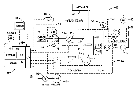
In a gas chromatographic system 10 illustrated in FIG. 1 , a
chromatographic column 12 is connected between an injector 14 and
a detector 16. The system is generally a split flow type, as
explained below. The column, injector and detector are
conventional, such as those associated with a Perkin-Elmer
AutoSystem GC equipped with an autosampler for sampling selected
sources of test material. A type of column that particularly
utilizes split flow is a capillary column. For example, the
column may be formed of a 25 m long fused silica tube 0.32 mm
internal diameter with a 5 ~m film of polydimethylsiloxane
stationary phase. The column alternatively may be a packed open
tubular column. The detector may be, for example, a hot wire, a
flame ionization or an electron capture type; however, the actual
detector is not critical to the present invention.
The injector means 14 (FIG. 2), which is conventional, is
constructed typically of a tubular housing 18 with a mixing
chamber 20 near the top (as shown, orientation not being
important). The mixing chamber is receptive of a carrier gas
through a~ inlet passage 22. At an injection fitting 2a above
the chamber is a septum 26 which is a thick (about 0.5 cm)
6
2~ ~~~~
silicone rubber disk. Test sample material, generally a liquid
that becomes vaporized or atomized, is selectively injected with
a syringe 28 through the septum by hand or from the autosampler
30 into the carrier gas to form a mixture. Sample material
generally is injected only momentarily, so that the mixture is a
pulse in the continuing flow of the carrier gas.
A glass tube 32 is retained in the housing with an o-ring 34 near
the top but below the inlet 22. A short length (e.g. about 1 cm)
of glass fiber 36 sits in the top of the tube to enhance mixing.
The carrier gas (selectively containing a pulse of sample) flows
through the tube down to the bottom of the injector. A fitting
42 holds the column at the bottom. The inlet point 43 for the
column taps a small test portion of the continuing flow of
carrier gas that contains injected sample to be pass into the
column. Most or all of the balance of the carrier gas (with any
sample therein) flows up through an annular passage 38 between
the housing and the tube, and is passed out of an exit passage
44. It will be appreciated that details of the injector may
differ from this example.
Unless turned off externally, a split portion of the carrier gas
is discharged through the passage 44. Splitting is done to allow
accurate gas regulation and a practical amount of sample to be
taken, while reducing the amount of sample that the column may
tolerate. The carrier gas, for example, may be helium, nitrogen,
hydrogen, air, or mixture such as argon and methane. As the
present system provides its own gas controls, the carrier supply
pressure into the system 10 need not be accurately maintained.
Carrier flow rate, for example, may be 100 ml/min, with 1 ml/min
being tapped to the column.
As indicated above, the mixing chamber 20 may be bounded on one
side by a septum 26 for the injection. In such a case, the
chamber should have an outlet passage 46 for a purge gas taken as
7
21~~D~
a portion of the carrier gas passed along the septum. The purge
gas, with a typical flow rate of about 2 ml/min, removes vapors
emitted from the septum during operation at elevated temperature,
vapors that otherwise could contaminate the carrier and its test
sample flowing to the column. The purge gas passes through a
fixed restrictor 47, such as a sintered, porous metal element, to
an ambient space 48. (As used herein and in the claims, the term
"ambient space" designates any region or condition at lower
pressure than the system, and usually is the atmosphere, but may
be a vacuum chamber, or a plenum to collect and filter the
outflow, or any other subsequent arrangement to dispose, use or
test the outflow.)
An ordinary pressure regulator 49 (either mechanical or
electrically controlled) maintains a constant pressure into the
restrictor 47, so as to maintain the purge gas at a constant flow
rate. A flowmeter 45 is disposed between the restrictor 47 and
the ambient space.
A pressure detector 50 measures the pressure substantially at the
inlet point 43 (FIG. 2) of the column passage 42. To achieve
this, the pressure detector may be disposed anywhere conveniently
in direct communication with the column inlet'point 43, for
example at the inlet 22, the purge passage 46 or the exit passage
44. The exit passage is preferable because it provides the
closest practical pressure location to the inlet point. A
similar detector 52 also should be provided to measure actual
ambient pressure relative to vacuum 54.
In operation, sample injection to the column are achieved with
regulation of both pressure and flow rate. Preferably the
operations are effected by a computer 56 including analog/digital
converters 58 as required for input and output (with appropriate
fior ;,- ,;t~1 ~ ~o , r
a~~pli c__c~,_ .. , a p o....ssing ~.ni 60 (CPU) , memor;~ 62, a
keyboard 64 or other means for operator input, and a display by a
8
21708
monitor 66 and/or printer. The computer also processes and
displays results from signals on an electrical line 68 from the
column detector 16 which shows variations in its output depending
on the injection of sample and its selective adsorption and
desorption by , or partitioning into and out of, the active
element in the column. It further is desirable to display
operating pressures, and to compute and display relative flows,
particularly mass flow rates and the "split ratio" (portion of
split flow to total). Generally an appropriate computer with
programming software and/or firmware is provided with a
commercial chromatographic system, such as a Perkin-Elmer Model
1022 GC Plus integrator, which uses an IntelT" 80386 processor
with "C" programming. For computing capacity in the present
application, a second processor may be utilized.
5 A flow control means 69 includes a flow rate detector, a variable
flow rate restrictor and a feedback flow controller there between
for closed loop operation. A gas inlet line 70 is disposed for
conveying the carrier gas at a selected inlet flow rate from a
gas source 72 to the inlet passage 22 into the injector 14. A
0 flow rate detector 74 is located in the inlet line to detect the
inlet flow rate. This detector advantageously comprises a fixed
gas restrictor element 76 inserted in the inlet line 70, and a
differential pressure detector 78 connected across, i.e. in
parallel to each end 80, 82 of, the fixed restrictor. Another
S pressure transducer 84 is used to measure inlet pressure to the
flow detector. With the restrictor 76 being calibrated, a
proportional signal from the differential detector provides a
direct measure of the inlet flow rate. The restrictor may be a
capillary tube, but preferably is a laminar flow type
0 advantageously formed of a 0.64 by 0.64 plug of sintered porous
type 316 stainless steel that provides a flow, for example, of
100 ml/min helium at 6.3 kg/cmZ (90 psi) input with 0.7 kg/cm2
(10 psi) drop across the restrictor. Other useful rates are from
1 to 300 ml/min. Calibration is effected readily by separately
9
21~~~~
connecting the restrictor into a system with a measured flow
rate.
A variable flow restrictor 86 is connected in the split flow
outlet between the exit passage 44 and the ambient space 48.
This restrictor is a conventional or other desired gas valve
device, that can be regulated. A suitable type is a variable
orifice effected by an electromagnet moving a rod end over a
small hole, such as a Porter Instrument Co. model EPC1001. An
alternative is a needle valve on a threaded stem controlled by a
stepper motor. For ~~splitless~~ flow, a separate solenoid shutoff
valve 87 is installed in the line 89 between the restrictor and
the flowmeter to ambient atmosphere. A carbon filter 88 should
be installed in the outlet line before the restrictor to remove
components from the sample that would clog the restrictor.
A feedback flow controller is operatively disposed between the
flow detector 74 and the outlet restrictor 86 to regulate this
restrictor with respect to inlet flow rate so as to maintain the
inlet flow rate constant. In one embodiment the controller is an
electronic amplifier that modifies an electrical signal from the
detector to send a corresponding current to the restrictor
control to adjust the restrictor appropriately. In an
advantageous embodiment the controller is incorporated into a
portion of the computer program 90 that is utilized to operate
the chromatographic system 10 and compute and display results.
The pressure signal from the transducer 78 is passed to the
computer. This pressure signal is compared to the pressure set
point, and the resulting difference is the error signal which is
passed through a standard PID (proportional, integral derivative)
control algorithm to compute the necessary restriction control
signal. This computes the control signal which is directed
thro»gh a digital/analog converter (or other signal cnnverr_er as
required) and amplifier to the restrictor control. Preferably,
2170~8~
the flow rate that is maintained is a mass flow rate. In such
case the computer program includes a modification that calculates
the feedback signal to the restrictor from stored information on
the gas characteristics, particularly viscosity, carrier supply
pressure and gas temperature.
In order to maintain a consistent flow rate through the
chromatographic column, a substantially constant pressure should
be maintained in the mixing chamber 20. To achieve this, the
system further preferably has a pressure control means for
regulating carrier gas flow through the inlet passage so as to
maintain the constant pressure. This effects a forward pressure
regulated mode, which is particularly desirable in conjunction
with the flow controller in the split flow.
In a preferred embodiment of a pressure control means 92, a
variable inlet flow restrictor 94 is disposed in the inlet line
70, between the flow rate detector 74 and the injector inlet 22.
This restrictor may be any type as described above for the outlet
restrictor, but need not be the same type. As indicated
previously, a pressure detector 50 is disposed to detect outlet
pressure substantially at the inlet point 43 of the column
passage. A pressure feedback controller is operatively disposed
to regulate the inlet restrictor with respect to the outlet
pressure so as to maintain the outlet pressure substantially
constant, for example at 0.7 kg/cm~ (10 psi) This feedback may
be similar to that used for the flow controller, and preferably
is incorporated into the computer programming 90.
For better accuracy it also is desirable to account for any
variations in ambient pressure. Thus the system should include
an additional transducer 52 (which may be the same type as the
differential transducer) for measuring absolute pressure of the
ambient space relative to vacuum. The feedback pressure
controller then further comprises means in the computation
11
CA 02170080 2004-06-03
responsive to the absolute pressure for compensating for
variations therein in regulating the outlet restrictor.
The foregoing system provides for forward pressure regulation
which is preferred for reasons of performance and mass flow
discrimination as illustrated in the aforementioned article by
Hinshaw. Moreover, by
dividing the flow control means 69 by locating the variable
restrictor 86 on the outlet line 44, and the f low detector 74 on
the inlet line 70, with feedback regulation therebetween, it has
become possible to provide regulated flow control for the split
flow outlet. (As pointed out in the Background hereinabove, flow
regulation with conventional controllers detecting flow rate in
the split flow outlet has not been practical.)
Although an electrically regulated flow controller is
particularly suited for carrying out the invention, it is
possible to use an adaptation of a mechanical flow controller of
the type disclosed in the aforementioned U.S. patent No.
4,096,746, The disclosed
controller comprises a diaphragm positioned by springs in
compression on either side, a one spring having adjustable
compression. A pressure drop is effected through a sintered
metal restrictor in the gas inlet, and the pressure drop is
applied across the diaphragm. The inlet gas pressure on one side
urges the diaphragm to open an channel in a control valve
assembly, to effect the controlled flow.
An adaptation of a mechanical flow controller is explained
briefly herein for illustration of an alternative means for
outlet flow control. In the adaptation', the restrictor is
removed from the controller (of the referenced patent).
Channelling is provided for the inlet flow to the valve assembly
WitilCW excrtlag SlgrliflCunt prc~,SSLirC On thE' dlupi'ira.J~.~i. Ti'1C
restrictor in the inlet line is then utilized. Pressure taps at
12
217fl~~~~
the inlet and outlet of the restrictor are led respectively to
either aide of the diaphragm to regulate the flow from the inlet
through the control valve assembly. In this way a mechanical
controller may be provided having separated flow control,
detection and regulation for incorporation into a system of the
present invention.
In further embodiments, means and method steps are provided for
effecting feedback control of carrier gas flow. The flow diagram
in FIG. 3 illustrates features effected in the computer
programming. It will be appreciated that, in the chromatographic
system, the programming of the feedback flow controller provides
the means and the steps for the feedback and other computations
and operations. However, other means such as electronic
circuitry may be substituted where practical.
The manufacturer's calibration of the fixed inlet restrictor may
be utilized if ordinary accuracy (e. g. about 10%) is sufficient.
For accuracy limited only by instruments (e. g. about 1%), further
calibration is effected, preferably as described below.
An initial step is calibrating the differential pressure as a
function of mass flow rate of carrier gas through the fixed inlet
restrictor. First, the column 12 (FIG. 1) is removed from the
injector fitting 42 and the hole is plugged. The flowmeter 45,
which is previously calibrated, is thereby situated to measure
mass flow rate of carrier gas through the fixed inlet restrictor.
With the flowmeter, a first calibration flow rate is established
102, and the actual flow rate and a first calibration pressure P1
are measured 104 with the differential detector 78, the
calibration pressure being the differential pressure across the
fixed inlet restrictor 76. A second calibration flow rate is
established 106, and the actual flow rate and a second
n r~ i n r ccttr D wr attr T' a i far t al
alib_ t_o.. p e......_e _1 a mea...._ed 108. h.. d_f~ er...i~_
pressures are stored 109. For reasons indicated below,
13
217~0~
temperature T~ of the second gas flow from the thermometer 96
(FIG. 1), and inlet pressure P=, from the gage 84, are each
measured 108 and stored 112.
The first calibration rate should be a minimum (low) flow rate,
generally at or almost zero flow with the variable pressure
control restrictor 94 off (small leakage through the turned-off
restrictor being possible). The second calibration flow rate is
a predetermined maximum flow rate. This is selected to be a
fraction, for example 60%, of the manufacturer's recommended
maximum for the restrictor 76. The flow rates are either
directed from the flowmeter 45 into the computer if such is
possible with the flowmeter, or read by an operator and fed into
the computer via the keyboard 64.
The flow rates should be standardized 114 to atmospheric pressure
and to standard absolute temperature prior to the step of
calculating. These are conventionally standardized by
multiplying a measured flow rate by a ratio of actual absolute
pressure of the atmosphere (or other ambient space) to standard
atmospheric pressure (1.03 kg/cm2 - 14.7 psi), and by a ratio of
standard atmospheric temperature (298 °K) to the actual absolute
temperature of the atmosphere. The standardized flows Fl and F,
corresponding respectively to pressures P, and P,, are stored
116.
Each of the calibration flow rates and pressures collectively are
parameters defining a function for calculating a differential
pressure (PS) from a flow (F~) through the restrictor. For best
accuracy the function may have higher order terms. However, a
linear function is adequate for the accuracy contempated herein:
3o PS = (F~-F,) ~ (PZ P') + P, (Eq. 1)
(F~_F~)
14
217003
In this case the pressure P$ is a set differential pressure, and
the flow F~ is a predetermined flow rate, as explained below.
This pressure is stored in the memory 62.
The flow rate F~ in Equation 1 should be a corrected mass flow
rate computed from a more basic set rate Fg that is predetermined
118 and stored 119. The set rate may be determined from operator
input at the time, or previously stored in the memory. The
correction made is for any change in characteristics of the
carrier gas used during operation from that of the carrier gas
during the step of calibrating. Thus the calculation of set
pressure P8 is a calculation with the function (Equation 1) from
the set flow rate by way of the corrected flow rate F~. Also
stored in memory 120 are characteristic information on the
carrier gas or gases used during calibration and operation.
Standardized viscosity of the calibration gas is (G,), and for
the carrier gas used during operation is (G,) (the same as G, if
the gas is the same). (Standardized viscosity means a ratio of
viscosity to that of a selected gas such as helium at standard
conditions.) A constant A is a temperature coefficient for the
fixed restrictor 76 and accounts for both viscosity and expansion
effects. The constant A is determined emperically, generally by
the manufacturer of the restrictor element; for example, a value
of O.Ss/°C was deemed suitable for the elements disclosed herein.
The system then is operated 122 normally (with the variable
restrictor controlling flow, the column 12 reinserted, and sample
injected intermittently) at the predetermined carrier gas flow
rate FS entered into the computer. Gas temperature T, and the
absolute inlet pressure P~3 are measured 124 and stored 125. The
corrected mass flow rate F~ is computed 126 with an equation:
__
~ ( ~ +A(T3-TZ)i ~',3 G3 (Eq. 2)
217~~~a
The set pressure P$ is calculated 128 with Equation 1 and stored
129.
During the normal operation 122, a signal representative of the
operational differential pressure P is directed 130 from the
detector 78 to the computer 56. A difference signal is generated
132 that is representative of the difference between the
differential pressure P and the set pressure P8 during operation
of the system. The difference signal is then utilized 134 by
feedback to regulate the variable outlet restrictor 86 so as to
l0 maintain the differential pressure substantially equal to the set
pressure during operation of the system. The inlet flow rate is
thereby maintained substantially constant at the set mass flow
rate.
The foregoing calibration function and correction for gas
characteristics may be combined to calculate 136 the actual mass
flow rate (F,,) of the carrier gas through the fixed inlet
restrictor 76 with further equations:
FA = F3 '~ (P~3~P~2) ~ (G3/G2) ' [1 +A(T3-Tz)1 IEq. 3)
whe re
2o F3 = [(F2-F,)/(PZ-P,11 " (P-P,1 + F,. (Eq. 41
and where P is the actual differential pressure measured. The
actual rate F" may be stored 137 and/or displayed 139 on the
monitor 66.
For the determination 118 of the set flow FS, it is desirable to
actually preselect 138 and store 141 an exit flow rate F$ in the
split vent line 44. An additional correction is made immediately
prior to an operation 122 of the system, preferably less than
five minutes prior, for example 30 seconds. For this, the valve
87 in the split vent is shut off 140, and a reduced mass flow
16
~~. ~~o
rate FA of the carrier gas is determined 142 and stored 143. The
set mass flow rate F8 is obtained 144 by adding the reduced mass
flow rate FR to the preselected exit mass flow rate Fs, and
stored 119. These steps may be effected automatically by the
system computer upon startup. Alternatively and more quickly,
but less accurately, a reduced mass flow rate may be estimated or
otherwise predetermined and stored, and the same value used
regularly instead of making the measurements each time.
The reduced flow rate is the sum of the purge and column flows
(plus leakage, if any). The correction establishes the actual
flow through the fixed inlet restrictor 76 where the control
pressure is being detected, so that the exit flow rate in the
split vent exit 44 can be preselected and used as the base flow
rate. The values can also be used to calculate 146, store 137
and display a split flow ratio S (ratio of split flow plus column
flow to column flow) which is a desired operating parameter for a
gas chromatographic system. Doing the preliminary flow
correction measurement immediately before an actual run reduces
effects of potential drift.
The calibration and feedback technique described above is
especially advantageous for a split flow system such as described
with respect to FIG. 1. However, the technique is also useful
where the variable restrictor and the flow detector components
are not divided as by the injector. For example, the combination
flow controller may be used in the same inlet line for a non-
split flow type of chromatographic system, such as driving a
packed column inlet. The technique is generally advantageous
for driving flow into a variable backpressure of a gas
chromatograph.
It is advantageous to combine components of each of the inlet and
outlet sides of the injector. Thus, in a further aspect, the
~y~t~:r, hay an integral inlet gas nodule and an integral outlet
gas module. The inlet module contains the fixed inlet
17
2~7~~8~
restrictor, the variable inlet restrictor, the differential
pressure detector, the gas temperature sensor and the carrier
supply pressure gage. The outlet module contains the variable
outlet restrictor and the column pressure detector.
A preferable construction is illustrated for the inlet module 200
(FIG. 4) based on a gas block 202 that has other components
mounted thereon. The fixed restrictor 76 is in the form of a
porous sintered metal plug sealed into a cylindrical cavity 203
in the block by a threaded disk 204 attached to the plug. A
solenoid 206 is fastened under the block by screws 208. A
flexible Viton'~' diaphragm 210 on the solenoid is held under a
pair of orifices 212 in the underside of the block (the orifices
not visible in this drawing, but being the same as orifices 265
in FIG. 5). Variable power to the solenoid via a cable 95 varies
the flow between the orifices to provide the variable restrictor
94 (FIG. 1) .
An end assembly 216 includes an end fitting 218 attached to the
block. The fitting includes a mounting bracket 220. The
pressure gage 84 (to atmosphere) in the form of a conventional
7.0 kg/cmz (100 psi) silicon transducer e.g. sold by IC Sensors,
Milpitas CT, part No. 1210A-100D-3N is mounted on the end fitting
so that electrical connectors 224 project accessibly. An
opposite end assembly 226 includes a second end fitting 228 with
another, similar transducer 78 for measuring differential
pressure across the fixed restrictor 76. A housing 232 attached
with screws 234 encloses the solenoid and most of the block. End
plates 236 are attached with screws 238 and washers 240 over the
transducers, and one plate supports an electrical connector 242
for a portion of the cable 95 from the computer 56 (FIG. 1) to
the solenoid. The block and end fittings have appropriate gas
passages 246 therein to direct the flows and provide pressure
taps lil the ;garner indlCatEd by FIG. i . ~-rims 2ii pl'OVid2
further seals where required. A fitting 248 for the carrier gas
18
2~.'~~~1~~~
is held on the block by a plate 250 with a screw 252, sealed by
an 0-ring 254. An outlet gas tube 256 from the block is
similarly provided.
The outlet module 260 (FIG. 5) is similar except that a fixed
restrictor and a differential pressure detector are not required
and are omitted. A gas block 262 has other components mounted
thereon. A solenoid 264, the same type as for inlet module, is
fastened to the block (the diaphram not being visible in FIG. 5).
Variable power to the solenoid via cable 85 varies the flow
between a pair of orifices 265 to effect the variable restrictor
86 (FIG. 1). An end fitting 266 is attached to the block. The
pressure gage 84 (to atmosphere) in the form of a conventional
silicon transducer is mounted on the end fitting. An end plate
268 is attached over the transducers and has a connector 270 for
the cable 85. The block and end fittings have appropriate other
gas passages 272 therein to direct the flows and provide a
pressure tap in the manner indicated by FIG. 1. Tubing 274
connected to the block provides for input and output of the split
flow and, for convenience, also includes pass-through for the
purge.
It will be appreciated that the modules provide a substantial
convenience despite the fact that the components in each are not
all used together. Thus the differential pressure detector 78
across the fixed restrictor 76 in the inlet module 200 provides
signals for feedback control of the variable restrictor 86 in the
outlet module 260. Conversely, the pressure gage 50 of the
second module 260 provides signals for feedback control of the
variable restrictor 94 of the inlet module 200.
While the invention has been described above in detail with
reference to specific embodiments, various changes and
tTiGuiiiCcW lGilS whlCh fail Withln tile Srlrit Ci the inVCh.tlGi. c'~ilC:
scope of the appended claims will become apparent to those
19
217~~81~
skilled in this art. Therefore, the invention is intended only
to be limited by the appended claims or their equivalents.