Sélection de la langue

Search

Sommaire du brevet 2170102 

Énoncé de désistement de responsabilité concernant l'information provenant de tiers

Une partie des informations de ce site Web a été fournie par des sources externes. Le gouvernement du Canada n'assume aucune responsabilité concernant la précision, l'actualité ou la fiabilité des informations fournies par les sources externes. Les utilisateurs qui désirent employer cette information devraient consulter directement la source des informations. Le contenu fourni par les sources externes n'est pas assujetti aux exigences sur les langues officielles, la protection des renseignements personnels et l'accessibilité.

Disponibilité de l'Abrégé et des Revendications

L'apparition de différences dans le texte et l'image des Revendications et de l'Abrégé dépend du moment auquel le document est publié. Les textes des Revendications et de l'Abrégé sont affichés :

  • lorsque la demande peut être examinée par le public;
  • lorsque le brevet est émis (délivrance).
(12) Brevet: (11) CA 2170102
(54) Titre français: UN APPAREIL POUR LE PEINTURAGE D'ARTICLES PAR PULVERISATION HUMIDE
(54) Titre anglais: AN APPARATUS FOR THE WET-PAINT SPRAY PAINTING OF ARTICLES
Statut: Périmé et au-delà du délai pour l’annulation
Données bibliographiques
(51) Classification internationale des brevets (CIB):
  • B05B 14/43 (2018.01)
(72) Inventeurs :
  • EDER, MICHAEL (Autriche)
(73) Titulaires :
  • BRAIN FLASH-PATENTENTWICKLUNGS GMBH
(71) Demandeurs :
  • BRAIN FLASH-PATENTENTWICKLUNGS GMBH (Autriche)
(74) Agent: SMART & BIGGAR LP
(74) Co-agent:
(45) Délivré: 2003-07-22
(22) Date de dépôt: 1996-02-22
(41) Mise à la disponibilité du public: 1996-08-25
Requête d'examen: 2000-02-17
Licence disponible: S.O.
Cédé au domaine public: S.O.
(25) Langue des documents déposés: Anglais

Traité de coopération en matière de brevets (PCT): Non

(30) Données de priorité de la demande:
Numéro de la demande Pays / territoire Date
A 343/95 (Autriche) 1995-02-24

Abrégés

Abrégé anglais


Apparatus for the wet-paint spray painting of articles having
a device for catching the paint surplus which has an air-permeable dry
filter, wherein the dry filter (4) is arranged movably and there is
provided a suction removal device (6) which sucks the dried paint
particles away from the dry filter (4).

Revendications

Note : Les revendications sont présentées dans la langue officielle dans laquelle elles ont été soumises.


6
CLAIMS:
1. Apparatus for wet-paint spray painting of articles, having a device for
catching
the paint surplus, which has an air-permeable dry filter, characterised in
that the
dry filter (4) is arranged movably and that there is provided a suction
removal
device (6) which sucks away from the dry filter (4) the paint particles which
have
dried on during a given time.
2. Apparatus according to claim 1 characterised in that the dry filter (4) is
drivable
by way of a drive motor (15).
3. Apparatus according to claim 2, characterised in that the drive motor (15)
is an
electrical drive motor.
4. Apparatus according to any one of claims 1 through 3 characterised in that
the
dry filter (4) is in the form of an endlessly circulating filter surface which
is
guided over direction-changing rollers (5).
5. Apparatus according to any one of claims 1 through 4 characterised in that
an
exhaust air passage (9) connected to an exhaust air installation is arranged
behind the side of the dry filter (4), which is remote from the article to be
painted, and the dry filter (4) is moved when the exhaust air installation is
switched on.
6. Apparatus according to any one of claims 1 through 5 characterised in that
the
dry filter (4) comprises an air-permeable flexible carrier (4a) and a filter
material
(4b) secured thereto.
7. Apparatus according to claim 6 characterised in that the filter material
(4b) is a
fleece.
8. Apparatus according to claim 7 characterised in that said fleece is made of
polyester or glass fibers.

7
9. Apparatus according to any one of claims 6 through 8 characterised in that
the
carrier (4a) is perforated.
10. Apparatus according to claim 9, characterised in that said carrier (4a)
comprises
conveyor belt material.
11. Apparatus according to any one of claims 6 through 8 characterised in that
the
carrier (4a) comprises air-permeable fabric.
12. Apparatus according to any one of claims 6 through 11 characterised in
that the
carrier (4a) and the filter material (4b) are glued together.
13. Apparatus according to any one of claims 1 through 12 characterised in
that on
its rear side the dry filter (4) has at least one guide projection (12).
14. Apparatus according to any one of claims 1 through 13 characterised in
that the
dry filter (4) has at least one row of holes into which a drive wheel (5)
engages
with pins (14).
15. Apparatus according to any one of claims 1 through 14 characterised in
that the
dry filter (4) is vertically oriented and is moved horizontally.
16. Apparatus according to claim 15 characterised in that at the top the dry
filter (4)
has guide elements (17) which are movably guided in a stationary horizontal
guide rail.
17. Apparatus according to any one of claims 1 through 16 characterised in
that the
dry filter (4) is moving and at least one suction intake opening (7) of the
suction
removal device (6) is movable over the dry filter (4) transversely to the
direction
of movement (21) thereof.
18. Apparatus according to claim 17 characterised in that the suction intake
opening(s) (7) is (are) provided on a suction nozzle (6a) which is guided
movably on a fixed guide means (22).

8
19. Apparatus according to claim 18, characterised in
that the suction nozzle (6a) is moved by motor means.
20. Apparatus according to claim 18 or claim 19
characterised in that the suction removal device comprises a
suction unit (6c) and the suction nozzle is connected by way
of a flexible hose (6b) to the suction unit (6c) of said
removal device.
21. Apparatus according to any one of claims 1 through
20 characterised in that the dry filter (4) receives paint
surplus in a region (8) and the suction removal device (6)
is arranged at a location which is remote from that region
(8).
22. Apparatus according to claim 21 characterised in
that the dry filter (4) moves in one direction and the
suction removal device (6) is arranged at a spacing, as
measured in the direction of movement (21) of the dry filter
(4), of at least 50% of the total length as measured in the
direction of movement (21) of the dry filter (4), from that
region (8) in which the dry filter (4) receives paint
surplus.
23. Apparatus according to claim 22, characterised in
that the spacing is at least 70% of the total length of the
dry filter (4).
24. Apparatus according to any one of claims 1 through
23 characterised by a device for mechanically knocking
against the dry filter (4).
25. Apparatus according to claim 24 characterised in
that said device knocks against the rear side of the dry
filter (4).

9
26. Apparatus according to any one of claims 1 through
25 characterised by a device for producing an air flow which
is directed through the dry falter (4) from the rear side
thereof to the front side thereof.

Description

Note : Les descriptions sont présentées dans la langue officielle dans laquelle elles ont été soumises.

21 701 02
Description
The invention concerns an apparatus for the wet-paint spray
painting of articles, having a device for catching the paint surplus,
which has an air-pPnm~able dry filter.
For catching the paint surplus in wet-paint spray painting
(that is to say when spray painting liquid media, for ~xAmrle by way
of spray no~les or spray guns), it is already known for the paint
surplus to be picked up by a filter surface and then ~7~ he~ out of the
filter surface. Such a wet separation procedure however must involve
the use of solvents which are not really envi~ ally ccmpatible,
and it is also necessary to provide drying devices in order to dry the
filter material after the washing operation.
Besides such wet separation procedures which are known for
example from German laid-open applications (DE-OS) Nos 36 18 642 and
43 00 400, it is also already known to use air-permeable dry filters
which are discarded after they are clogged by the paint surplus. That
is not only uneconomical but also prohibitive from the point of view
of safeguarding the environment.
The object of the present invention is to provide an
environmentally compatible apparatus which is inexpensive in operation
for the wet-paint spray painting of articles.
In accordance with the invention, in an apparatus of the
general kind set forth in the opening part of this specification, that
is achieved in that the dry filter is arranged movably and that there
is provided a suction removal device which sucks away from the dry
filter the paint particles which have dried on during a given time.
The invention is based on the realization that there is no
need in the wet-paint spray painting operation to wash out the paint
surplus which is caught by the filter with liquid solvent in a wet
separation procedure, but that on the contrary it is sufficient to
suck the paint surplus away from the dry filter after a given drying
section, so that the dry filter does not have to be discarded. Suction
removal of matter fram filters has long been known in the case of
powder coating installations. In such installations a powder is

2170102
'
~plie~ electrostatically to the articles to be coated and the powder
surplus is sucked away (see for example DE 28 13 854 C2). In contrast
thereto the invention concerns a different general kind of subject-
matter, namely wet-paint spray painting with liquid media. In that
wet-paint spray painting procedure, in contrast to mere powder, the
paint surplus clings subsL~ILially more firmly to the filter surface
and it was therefore hitherto considered that either a dry filter had
to be discarded or it had to be washed out in an expensive wet
process. Surprisingly however the applicants' tests have shown that,
even in the wet-paint spray painting of articles, the paint surplus
can be sucked away frcm a dry filter without involving an expensive
wet separation procedure.
In that respect it is particularly advantageous if the
suction removal device is disposed at a location which is remote from
that region in which the dry filter receives the paint surplus because
then the paint particles, even in the case of a continuously moved dry
filter, have sufficient time to dry completely so that they can be
easily sucked away.
Further advantages and details of the invention will be
described more fully with reference to the following specific
description.
Figure 1 is a plan view of an embodiment of an apparatus
according to the invention for the hand wet-paint spray painting of
articles,
25Figure 2a is a view in cross-section of an embodiment of a
dry filter according to the invention,
Figure 2b showsan underview of the Figure 2a dry filter,
Figure 3 shows a direction-changing drum for the movable dry
filter according to the invention,
30Figure 4 is a front view of a further embodiment of a device
according to the invention for catching the paint surplus,
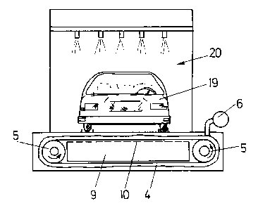
Figure 5 shows an embodiment for spray painting of a motor
vehicle, and

2170102
Figure 6 is a diay~ llaLic perspective view of an embodiment
of a suction removal device with a suction nozzle which is movable
transversely to the dry filter.
Figure 1 shows an apparatus for the wet-paint spray painting
of articles 1 by means of a hand-operable spray gun 2 which for
~xAmple has a container for liquid paint and which is connected to a
c~"~lessed air line 3. In accordance with the invention, provided for
catching the paint surplus which goes past the article 1 is an air-
p~rme~hle dry filter 4 which is arranged movably over direction-
changing dr~ms 5. In addition, in accordance with the invention thereis provided a suction removal device 6 whose suction intake opening 7
is disposed at a location which is as far removed as possible, in the
direction of movement of the dry filter 4, from the region 8 in which
the dry filter receives paint excess. Connected between the front run
and the rear run of the ~n~l~ssly circulating dry filter is an exhaust
air passage 9 of an exhaust air installation which sucks air out of
the exhaust air passage 9. The front side of the exhaust air passage 9
is of an air-pPrme~hle configuration or is perforated at the location
10 so that the exhaust air which passes through the dry filter 4 can
pass into the exhaust air passage 9. When that happens the paint
particles are caught by the dry filter 4 and are later removed by
suction by the suction removal device 6. In that way it is possible
for the dry filter 4 to be continuously cleaned. The dry filter can be
continuously moved. However discontinuous movement is also possible,
for example in a separate cleaning run in the evening.
The dry filter 4 is advantageously of a two-part
configuration, namely comprising an air-permeable statically stable
but nonetheless flexible carrier 4a and the actual dry filter material
4b. The filter material is preferably a fleece, desirably a polyester
fleece or a glass fiber fleece , which is of a height of typically
some centimeters. The carrier 4a can be provided with holes 11, as is

2170102
shown by the view from below in Figure 2b. Desirably the carrier
comprises conveyor material, for ~x~mple fiber-reinforced rubber. It
is also possible for the carrier 4a to be formed from an air-p~rm~ahle
fabric (that is to say without discrete holes 11).
For the purposes of joining the carrier 4a to the actual
filter material 4b, it is desirable for them to be glued together.
In order to permit a guidance effect for the circulating dry
filter 4, two guide projections 12 are provided at the rear side of
the dry filter 4 in the embodiment shown in Figures 2a and 2b. Those
guide projections 12 can then be guided in suitable guide grooves (not
shown) in the direction-changing rollers S and then guide the
circulating dry filter 4 in the transverse direction.
In the embodiment shown in Figure 3, for the purposes of
guiding the circulating dry filter 4 and to provide for exact drive
thereof, it is provided that the carrier 4a has at least one row of
holes 13 into which engage pins 14 arranged on the guide roller 5
which is in the form of a drive wheel. The drive wheel 5 is driven by
an electric motor 15 disposed thereabove, possibly by way of a
transmission (not shown). The electric motor 15 is controlled by a
control device 16.
In the ~mhn~iment shown in Figure 4 the dry filter 4 also
circulates in the horizontal direction. ~ nce in the vertical
direction is effected by virtue of the fact that at the top the dry
filter 4 has guide elements 17 which are guided in a stationary
horizontal guide rail 18 (similarly to a curtain rail). The guide rail
18 can be endlessly taken around the entire periphery above the dry
filter. It is however also possible for the guide rail 18 to be
disposed only in the front region and the rear region and for the
vertical guidance effect in the region of the direction-changing
rollers 5 to be afforded by other means, for example by the pins 14
which engage into the rows of holes 13.

2170102
-
Figure 5 shows an apparatus for the spray painting of a motor
vehicle 19. Here the dry filter 4 is oriented horizontally and runs
beneath the spray cabin 20.
In the embodiment shown in Figure 6 the suction intake
opening 7 of the suction removal device is moved transversely to the
direction of movement 21 of the dry filter 4. This has the advantage
that it is possible to use a small suction noz~le 6a with a high local
suction capability in order to suck the dried paint particles away
from the dry filter 4. The suction nozzle 6a is connected by way of a
10 fl~xihle hose 6b to the suction unit 6c of the suction removal device.
The arrangement has two fixed guide rails 22 which guide the suction
nozzle 6a. The movement of the suction nozzle 6a in the vertical
direction in Figure 6 is preferably effected by way of a motor drive
(not shown), for example by way of a cable pull drive, a spindle
drive, a toothed rack drive or the like.
In general the extraction effect will be achieved just with
the suction removal action. In cases of a special nature however it is
also possible to arrange at the rear side (side of the carrier 4a) of
the conveyor belt 4 a device 23 for mechanically knocking against the
dry filter 4 in order to be able better to detach the paint particles
therefrcm. The device 23 can also serve to produce an air flow which
is directed from the rear side of the dry filter 4 to the front side
and which thus prcmotes the suction removal air movement.

Dessin représentatif
Une figure unique qui représente un dessin illustrant l'invention.
États administratifs

2024-08-01 : Dans le cadre de la transition vers les Brevets de nouvelle génération (BNG), la base de données sur les brevets canadiens (BDBC) contient désormais un Historique d'événement plus détaillé, qui reproduit le Journal des événements de notre nouvelle solution interne.

Veuillez noter que les événements débutant par « Inactive : » se réfèrent à des événements qui ne sont plus utilisés dans notre nouvelle solution interne.

Pour une meilleure compréhension de l'état de la demande ou brevet qui figure sur cette page, la rubrique Mise en garde , et les descriptions de Brevet , Historique d'événement , Taxes périodiques et Historique des paiements devraient être consultées.

Historique d'événement

Description Date
Inactive : CIB désactivée 2021-10-09
Inactive : CIB en 1re position 2020-01-17
Inactive : CIB attribuée 2020-01-17
Inactive : CIB expirée 2018-01-01
Le délai pour l'annulation est expiré 2009-02-23
Lettre envoyée 2008-02-22
Inactive : Lettre officielle 2007-02-09
Inactive : Paiement correctif - art.78.6 Loi 2007-01-25
Accordé par délivrance 2003-07-22
Inactive : Page couverture publiée 2003-07-21
Lettre envoyée 2003-06-26
Inactive : Transfert individuel 2003-05-06
Inactive : Taxe finale reçue 2003-04-10
Préoctroi 2003-04-10
Un avis d'acceptation est envoyé 2002-12-11
Lettre envoyée 2002-12-11
Un avis d'acceptation est envoyé 2002-12-11
Inactive : Approuvée aux fins d'acceptation (AFA) 2002-11-29
Modification reçue - modification volontaire 2002-09-23
Inactive : Dem. de l'examinateur par.30(2) Règles 2002-05-27
Inactive : Grandeur de l'entité changée 2002-03-08
Inactive : Renseign. sur l'état - Complets dès date d'ent. journ. 2000-03-14
Lettre envoyée 2000-03-14
Inactive : Dem. traitée sur TS dès date d'ent. journal 2000-03-14
Toutes les exigences pour l'examen - jugée conforme 2000-02-17
Exigences pour une requête d'examen - jugée conforme 2000-02-17
Demande publiée (accessible au public) 1996-08-25

Historique d'abandonnement

Il n'y a pas d'historique d'abandonnement

Taxes périodiques

Le dernier paiement a été reçu le 2003-02-17

Avis : Si le paiement en totalité n'a pas été reçu au plus tard à la date indiquée, une taxe supplémentaire peut être imposée, soit une des taxes suivantes :

  • taxe de rétablissement ;
  • taxe pour paiement en souffrance ; ou
  • taxe additionnelle pour le renversement d'une péremption réputée.

Veuillez vous référer à la page web des taxes sur les brevets de l'OPIC pour voir tous les montants actuels des taxes.

Historique des taxes

Type de taxes Anniversaire Échéance Date payée
TM (demande, 2e anniv.) - petite 02 1998-02-23 1998-01-22
TM (demande, 3e anniv.) - petite 03 1999-02-22 1999-01-28
TM (demande, 4e anniv.) - petite 04 2000-02-22 2000-02-16
Requête d'examen - petite 2000-02-17
TM (demande, 5e anniv.) - petite 05 2001-02-22 2001-02-07
TM (demande, 6e anniv.) - générale 06 2002-02-22 2002-02-22
TM (demande, 7e anniv.) - générale 07 2003-02-24 2003-02-17
Taxe finale - générale 2003-04-10
Enregistrement d'un document 2003-05-06
TM (brevet, 8e anniv.) - générale 2004-02-23 2004-01-26
TM (brevet, 9e anniv.) - générale 2005-02-22 2005-02-22
TM (brevet, 10e anniv.) - générale 2006-02-22 2006-02-10
2007-01-25
TM (brevet, 11e anniv.) - générale 2007-02-22 2007-01-31
Titulaires au dossier

Les titulaires actuels et antérieures au dossier sont affichés en ordre alphabétique.

Titulaires actuels au dossier
BRAIN FLASH-PATENTENTWICKLUNGS GMBH
Titulaires antérieures au dossier
MICHAEL EDER
Les propriétaires antérieurs qui ne figurent pas dans la liste des « Propriétaires au dossier » apparaîtront dans d'autres documents au dossier.
Documents

Pour visionner les fichiers sélectionnés, entrer le code reCAPTCHA :


Pour visualiser une image, cliquer sur un lien dans la colonne description du document. Pour télécharger l'image (les images), cliquer l'une ou plusieurs cases à cocher dans la première colonne et ensuite cliquer sur le bouton "Télécharger sélection en format PDF (archive Zip)" ou le bouton "Télécharger sélection (en un fichier PDF fusionné)".

Liste des documents de brevet publiés et non publiés sur la BDBC .

Si vous avez des difficultés à accéder au contenu, veuillez communiquer avec le Centre de services à la clientèle au 1-866-997-1936, ou envoyer un courriel au Centre de service à la clientèle de l'OPIC.


Description du
Document 
Date
(aaaa-mm-jj) 
Nombre de pages   Taille de l'image (Ko) 
Dessin représentatif 2003-05-01 1 8
Page couverture 2003-06-17 1 30
Abrégé 1996-06-04 1 9
Page couverture 1996-06-04 1 16
Description 1996-06-04 5 223
Revendications 1996-06-04 3 98
Dessins 1996-06-04 3 58
Revendications 2002-09-23 4 126
Dessin représentatif 1998-03-19 1 9
Rappel de taxe de maintien due 1997-10-23 1 111
Accusé de réception de la requête d'examen 2000-03-14 1 178
Avis du commissaire - Demande jugée acceptable 2002-12-11 1 160
Courtoisie - Certificat d'enregistrement (document(s) connexe(s)) 2003-06-26 1 105
Avis concernant la taxe de maintien 2008-04-07 1 172
Taxes 2003-02-17 1 38
Correspondance 2003-04-10 1 33
Taxes 2002-02-22 1 37
Taxes 2000-02-16 2 65
Taxes 2005-02-22 1 36
Correspondance 2007-02-09 1 12
Taxes 2007-01-31 1 35