Note : Les descriptions sont présentées dans la langue officielle dans laquelle elles ont été soumises.
~., ~ 17 417
BACKGROUND OF THE INVENTION
The invention relates to steerable rotary drilling systems.
When drilling or coring holes in subsurface formations, it is sometimes
desirable to
be able to vary and control the direction of drilling, for example to direct
the borehole
towards a desired target, or to control the direction horizontally within the
payzone once
the target has been reached. It may also be desirable to correct for
deviations from the
desired direction when drilling a straight hole, or to control the direction
of the hole to
avoid obstacles.
Rotary drilling is defined as a system in which a bottom hole assembly,
including
IO the drill bit, is connected to a drill string which is rotatably driven
from the drilling
platform at the surface. Hitherto, fully controllable directional drilling has
normally
required the drill bit to be rotated by a downhole motor. The drill bit may
then, for
example, be coupled to the motor by a double tilt unit whereby the central
axis of the drill
bit is inclined to the axis of the motor. During normal drilling the effect of
this inclination
is nullified by continual rotation of the drill string, and hence the motor
casing, as the bit is
rotated by the motor. When variation of the direction of drilling is required,
the rotation
of the drill string is stopped with the bit tilted in the required direction.
Continued rotation
of the drill bit by the motor then causes the bit to drill in that direction.
" ~-
Although such arrangements can, under favourable conditions, allow accurately
controlled directional drilling to be achieved using a downhole motor to drive
the drill bit,
there are reasons why rotary drilling is to be preferred, particularly in long
reach drilling.
Accordingly, some attention has been given to arrangements for achieving a
fully
steerable rotary drilling system. For example, British Patent Specification
No. 2259316
descn'bes various steering arrangements in which there is associated with the
rotary drill bit
a modulated bias unit. The bias unit comprises a number of hydraulic actuators
spaced
-1-
~., 21 '~ ~ 1 '~
apart around the periphery of the unit, each having a movable thrust member
which is
hydraulically displaceable outwardly for engagement with the formation of the
borehole
being drilled. Each actuator has an inlet passage for connection to a source
of drilling fluid
under pressure and an outlet passage for communication with the annulus. A
control valve
connects the inlet passages in succession to the source of fluid under
pressure, as the bias
unit rotates. The valve serves to modulate the fluid pressure supplied to each
actuator in
synchronism with rotation of the drill bit, and in selected phase relation
thereto whereby,
as the drill bit rotates, each movable thrust member is displaced outwardly at
the same
selected rotational position so as to bias the drill bit laterally and thus
control the direction
of drilling.
In operation of a steerabie rotary drilling system of this kind, it may be
required,
when the borehole is being drilled in the required direction, to turn off or
reduce the
biasing effect of the modulated bias unit so as, for example, to drill a
straight section of the
borehole. The present invention provides, in one aspect, a modulated bias unit
whereby
the biasing effect of the unit may be readily turned off or reduced during
drilling
operations.
SLTIvIMARY OF THE IIWENTION
According to the first aspect of the invention, there is provided a modulated
bias
unit, for use in a steerable rotary drilling system, of the kind including at
least one
hydraulic actuator, at the periphery of the unit, having a movable thrust
member which is
hydraulically displaceable outwardly for engagement with the formation of the
borehole
being drilled, and a control valve operable to bring the actuator alternately
into and out of
communication with a source of fluid under pressure, as the bias unit rotates
so that, in
use, the fluid pressure to the actuator may be modulated in synchronism with
rotation of
the drill bit, and in selected phase relation thereto, whereby the movable
thrust member can
-2-
21'~~17~
be displaced outwardly at the same rotational position of the bias unit, the
bias unit being
characterised by the provision of auxiliary valve means, preferably in series
with said
control valve, operable between a first position where it permits the control
valve to pass a
maximum supply of fluid under pressure to the hydraulic actuator, and a second
position
where it prevents the control valve from passing said maximum supply of fluid
under
pressure to the hydraulic actuator. The invention is applicable to a bias unit
where there
is provided only a single hydraulic actuator, but preferably, as previously
mentioned, there
are provided a phuality of hydraulic actuators spaced apart around the
periphery of the
unit, said control valve then being operable to bring the actuators
successively into and out
of communication with said source of fluid under pressure, as the bias unit
rotates.
The auxiliary valve means may be located upstream or downstream of the control
valve, although upstream is preferred, for practical reasons, in the preferred
embodiment
to be described.
Preferably the auxiliary valve means is adapted to cut off the supply of fluid
to the
hydraulic actuator substantially completely when in said second position.
Alternatively, the auxiliary valve means may be adapted, when in its second
position, to direct a proportion of the fluid under pressure away from the
hydraulic
actuator and to a lower pressure zone, such as the annulus between the drill
string and the
walls of the borehole.
The control valve may include two relatively rotatable parts comprising a
first part
having an inlet aperture in communication with said source of fluid under
pressure and a
second part having at least one outlet aperture in communication with said
hydraulic
actuator, said inlet aperture, in use, being brought successively into and out
of
communication with said outlet aperture on relative rotation between said
valve parts, the
aforesaid auxiliary valve means comprising third and fourth parts, the fourth
part being
-3-
,, 217~:~'~~
movable relative to the third part between said first position where it allows
fluid to pass
through the control valve to the actuator and said second position where it at
least reduces
such flow.
Said control valve may be a disc valve wherein said relatively rotatable parts
comprise two contiguous co-axial discs, and in this case said auxiliary valve
means may
comprise co-axial third and fourth discs, each formed with at least one
aperture and which
exposes an aperture of the other when in said first position relative thereto
and at least
partly closes said aperture when in said second position relative thereto.
Although any suitable means may be provided to effect operation of the
auxiliary
valve means, according to preferred embodiments of the imrention said third
and fourth
parts constituting the auxiliary valve means may be moved between their first
and second
relative positions by the reversal of the direction of relative rotation
between said first and
second parts of the control valve. The two parts of the auxiliary valve means
may be
connected by a lost motion connection whereby said lost motion is taken up
upon reversal
of the direction of relative rotation.
Such arrangement has the important advantage of requiring only a minimum of
extra hardware to be added to the basic bias unit system. This system will
normally
akeady include means for controlling the relative rotation between the parts
of the control
valve, so that the reverse operation of the control valve necessary to operate
the auxiliary
valve means is akeady available. It is therefore only necessary to couple to
the control
valve the actual components of the auxiliary valve itself, and no additional
control
mechanism for controlling operation of the auxiliary valve is required.
Accordingly, this
preferred embodiment of the invention may provide simplicity as well as
intrinsic reliability.
In a preferred arrangement, a control shaft drives the first part of the
control valve
through the lost motion connection, one part of the auxiliary valve means
being connected
-4-
21'~ ~ 1'~
to the control shaft, and the other part of the auxiliary valve means being
mechanically
connected to the first part of the control valve. In this case, the second
part of the control
valve is connected to the bias unit body.
The mechanical connection between the other part of the auxiliary valve and
the
first part of the control valve contains a fluid passage from the aperture on
the other part
of the auxiliary valve to the aperture on the first part of the control valve.
These two parts
may be bonded together, for example by brazing or glueing, or they could
comprise
integral portions of a single component.
In another, non-preferred, arrangement the first part of the control valve is
connected directly to the control shaft and the second part is connected to
the body
through a lost motion connection, one part of a multiple auxiliary valve being
connected to
the second part of the control valve and the other to the bias unit body.
BRIEF DESCRIPTION OF THE DRAWIrTGS
Figure 1 is a diagrammatic sectional representation of a deep hole drilling
1 S installation,
Figure 2 is a part-longitudinal section, part side elevation of a prior art
modulated
bias unit of the kind to which the present invention may be applied,
Figures 3 and 4 are plan views of the two major components of the disc valve
employed in the prior art bias unit,
Figure 5 is a diagrammatic longitudinal section through a roll stabilised
instrumentation package, acting as a control unit for the bias unit of Figures
2-4,
Figure 6 is a longitudinal section, on an enlarged scale, of a modified form
of disc
valve, in accordance with the invention, employed in the bias unit,
Figures 7 and 8 are diagrammatic plan views of two of the elements of the disc
valve of Figure 6, showing first and second ~sitions thereof respectively and,
-5-
2 ~. '~ ~ ~ '~ ~
Figures 9 and 10 are similar views to Figures 7 and 8, showing an alternative
construction for the disc valve.
DETAILED DESCRIPTION OF THE PREFERRED EMBODI1VVIENTS
In the following description the terms "clockwise" and "anti clockwise" refer
to the
direction of rotation as viewed looking downhole.
Figure 1 shows diagrammatically a typical rotary drilling installation of a
kind in
which the system according to the present invention may be employed.
As is well known, the bottom hole assembly includes a drill bit l, and is
connected
to the lower end of a drill string 2 which is rotatably driven from the
surface by a rotary
table 3 on a drilling platform 4. The rotary table is driven by a drive motor
indicated
diagrammatically at 5 and raising and lowering of the drill string, and
application of
weight-on-bit, is under the control of draw works indicated diagrammatically
at 6.
The bottom hole assembly includes a modulated bias unit 10 to which the drill
bit 1
is connected and a roll stabilised control unit 9 urhich controls operation of
the bias unit 10
in accordance with an on-board computer program, andlor in accordance with
signals
transmitted to the control unit from the surface. The bias unit 10 may be
con~olled to
apply a lateral bias to the drill bit 1 in a desired direction so as to
control the direction of
drilling.
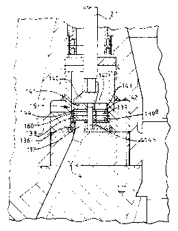
Referring to Figure 2, the bias unit 10 comprises an elongate main body
structure
provided at its upper end with a threaded pin 11 for connecting the unit to a
drill collar,
incorporating the roll stabilised control unit 9, which is in turn connected
to the lower end
of the drill string. The lower end 12 of the body structure is formed with a
socket to
receive the threaded pin of the drill bit. The drill bit may be of any type.
There are provided around the periphery of the bias unit, towards its lower
end,
three equally spaced hydraulic actuators 13. Each hydraulic actuator 13 is
supplied with
-6-
.. 21'7~1'~4
drilling fluid under pressure through a respective passage 14 under the
control of a
rotatable disc valve 15 located in a cavity 16 in the body structure of the
bias unit. Drilling
fluid delivered under pressure downwardly through the interior of the drill
string, in the
normal manner, passes into a central passage 17 in the upper part of the bias
unit, through
a filter 18 consisting of closely spaced longitudinal wires, and through an
inlet i9 into the
upper end of a vertical multiple choke unit 20 through which the drilling
fluid is delivered
downwardly at an appropriate pressure to the cavity 16.
The disc valve 15 is controlled by an axial shaft 21 which is connected by a
coupling 22 to the output shaft of the roll stabilised control unit 9.
The roll stabilised control unit maintains the shaft 21 substantially
stationary at a
rotational orientation which is selected, either from the surface or by a
downhole computer
program, according to the direction in which the drill bit is to be steered.
As the bias unit
rotates around the stationary shaft 21 the disc valve 15 operates to deliver
drilling fluid
under pressure to the three hydraulic actuators 13 in succession. The
hydraulic actuators
are thus operated in succession as the bias unit rotates, each in the same
rotational position
so as to displace the bias unit laterally in a selected direction. The
selected rotational
position of the shaft 21 in space thus determines the direction in which the
bias unit is
actually displaced and hence the direction in which the drill bit is steered.
Figures 3 and 4 show in greater detail the construction of the components of
the
prior art disc valve 15. The disc valve comprises a lower disc 136 which is
fixedly
mounted, for example by brazing or glueing, on a faced part of the body
structure of the
bias unit. The lower disc 136 comprise an upper layer of polycrystalline
diamond bonded
to a thicker substrate of cemented tungsten carbide. As best seen in Figure 4
the disc 136
is formed with three equally circumferentially spaced circular apertures 137
each of which
registers with a respective passage 14 in the body structure of the bias unit.
CA 02170174 2005-10-19
The upper disc 138 is brazed or glued to a shaped element on the lower end of
the
shaft 21 and comprises a lower facing layer of polycrystalline diamond bonded
to a thicker
substrate of tungsten carbide. As best seen in Figure 3, the disc 138 is
formed with an
arcuate aperture 139 extending through approximately 180°. The
arrangement is such that
as the lower disc 136 rotates beneath the upper disc 138 (which is held
stationary, with the
shaft 21, by the aforementioned roll stabilised control unit 9) the apertures
137 are
successively brought into communication with the aperture 139 in the upper
disc so that
drilling fluid under pressure is fed from the cavity 16, through the passages
14, and to the
hydraulic actuators in succession. It will be seen that, due to the angular
extent of the
aperture 139, a following aperture 137 begins to open before the previous
aperture has
closed.
In order to locate the discs 136 and 138 of the disc valve radially, an axial
pin of
polycrystalline diamond may be received in registering sockets in the two
discs.
Figure S shows diagrammatically, in greater detail, one form of roll
stabilised
1 S control unit for controlling a bias unit of the kind shown in Figure 2.
Other forms of roll
stabilised control unit are described in British Patent Specification No.
2,257,182 and in
co-pending Publication No. GB 2,298,217.
Referring to Figure 5, the support for the control unit comprises a tubular
drill
collar 23 forming part of the drill string. The control unit comprises an
elongate generally
cylindrical hollow instrument carrier 24 mounted in bearings 25, 26 supported
within the
drill collar 23, for rotation relative to the drill collar 23 about the
central longitudinal axis
thereof. The carrier has one or more internal compartments which contain an
instrument
package 27 comprising sensors for sensing the rotation and orientation of the
control unit,
and associated equipment for processing signals from the sensors and
controlling the
rotation of the carrier.
_g_
.- 21'~~I7~
At the lower end of the control unit a mufti-bladed impeller 28 is rotatably
mounted on the Garner 24. The impeller comprises a cylindrical sleeve 29 which
encircles
the carrier and is mounted in bearings 30 thereon. The blades 31 of the
impeller are rigidly
mounted on the lower end of the sleeve 29. During drilling operations the
drill string,
including the drill collar 23, will normally rotate clockwise, as indicated by
the arrow 32,
and the impeller 28 is so designed that it tends to be rotated anti-clockwise
as a result of
the flow of drilling fluid down the interior of the collar 23 and across the
impeller blades
31.
The impeller 28 is coupled to the instrument carrier 24, by an el~trical
torquer-
i0 generator. The sleeve 29 contains around its inner periphery a pole
strocture comprising
an array of permanent magnets 33 cooperating with an armature 34 faced within
the carrier
24. The magnet/armature arrangement serves as a variable drive coupling
between the
impeller 28 and the carrier 24.
A second impeller 38 is mounted adjacent the upper end of the Garner 24. The
second impeller is, like the first impeller 28, also coupled to the carrier 24
in such a manner
that the torque it imparts to the carrier can be varied. The upper impeller 38
is generally
similar in construction to the lower impeller 28 and comprises a cylindrical
sleeve 39 which
encircles the carrier casing and is mounted in bearings 40 thereon. The blades
41 of the
impeller are rigidly mounted on the upper end of the sleeve 39. However, the
blades of the
upper impeller are so designed that the impeller tends to be rotated clockwise
as a result of
the flow of drilling fluid down the interior of the collar 23 and across the
impeller blades
41.
Like the impeller 28, the impeller 38 is coupled the carrier 24 by an
electrical
torquer-generator. The sleeve 39 contains around its inner periphery an array
of
permanent magnets 42 cooperating with an armature 43 fixed within the Garner
24. The
-9-
,.", ~17~1'~~
magnetJarmature arrangement serves as a variable drive coupling between the
impeller 38
and the earner.
As the drill collar 23 rotates during drilling, the main bearings 25, 26 and
the disc
valve 15 of the bias unit apply a clockwise input torque to the carrier 24 and
a fiuther
clockwise torque is applied by the upper impeller 38 through the torquer-
generator 42,43
and its bearings 40. These clockwise torques are opposed by an anti-clockwise
torque
applied to the carrier by the lower impeller 28. The torque applied to the
carrier 24 by
each impeller may be varied by varying the electrical load on each generator
constituted by
the magnets 33 or 42 and the armature 34 or 43. This variable load is applied
by a
generator load control unit under the control of a micro-processor in the
instrument
package 27. During steered drilling there are fed to the processor an input
signal
indicative of the required rotational orientation (roll angle) of the carrier
24, and feedback
signals from roll sensors included in the instnzment package 27. The input
signal may be
transmitted to the control unit from the surface, or may be derived from a
downhole
program defining the desired path of the borehole being drilled in comparison
with survey
data derived downhole.
The processor is pre-programmed to process the feedback signal which is
indicative of the rotational orientation of the carrier 24 in space, and the
input signal which
is indicative of the desired rotational orientation of the earner, and to feed
a resultant
output signal to generator load control units. During steered drilling, the
output signal is
such as to cause the generator load control units to apply to the torquer-
generators 33, 34
and 42,43 electrical loads of such magnitude that the net anticlockwise torque
applied to
the carrier 24 by the two torquer-generators opposes and balances the other
clockwise
torques applied to the carrier, such as the bearing torque, so as to maintain
the carrier non
rotating in space, and at the rotational orientation demanded by the input
signal.
-10-
~17~~.'~~
The output from the control unit 9 is provided by the rotational orientation
of the
carner itself and the carrier is thus mechanically connected by a single
control shaft 35 to
the input shaft 21 of the bias unit 10 shown in Figure 2.
During normal steering operation of the control unit and bias unit, the
clockwise
S torque applied by the second, upper impeller 38 may be maintained constant
so that
co~rol of the rotational speed of the control unit relative to the drill
collar, and its
rotational position in space, are determined solely by control of the main,
lower impeller
28, the constant clockwise torque of the upper impeller being selected so that
the main
impeller operates substantially in the useful, linear part of its range.
However, since the clockwise torque may also be varied by varying the
electrical
load on the upper torquer-generator 42; 43 control means in the iostiument
package may
control the two torquer-generators in such manner as to cause any required net
torque,
within a permitted range, to be applied to the carrier by the impellers. This
net torque will
be the difference between the clockwise torque applied by the upper impeller
38, bearings
etc. and the anticlockwise torque applied by the lower impeller 28. The
control of net
torque provided by the two impellers may therefore be employed to roll
stabilise the
control unit during steering operation, but it may also be employed to cause
the control
unit to perform rotations or part-rotations in space, or relative to the drill
collar 23, either
clockwise or anti-clockwise or in a sequence of both, and at any speed within
a permitted
range. For rotation relative to the drill collar the torquers are controlled
by a sensor
providing signals dependent on the angle between the instrument carrier 24 and
the drill
collar 23, and/or its rate of change.
According to the present invention, the control valve 15 of the bias unit
shown in
Figures 2-4 is modified to permit turning off or reduction of the biasing
effect of the unit
-11-
.. 21'~~~7~
during drilling. One form of modified control valve according to the invention
is shown in
greater detail in Figures b-8.
Referring to Figure 6, as in the prior art arrangement previously described
the
lower disc i36 of the disc valve 15 is brazed or glued on a faced part of the
body structure
of the bias unit and the disc 136 is formed with three equally
circumferentially spaced
circular apertures 137 each of which registers with a respective passage 14 in
the body
structure.
However, in the arrangement according to the imrentioa the upper disc 138 is
not
directly brazed or glued to the element 140 on the lower end of the shaft 21
but is instead
brazed to the tungsten carbide face of a similar third disc 160 which is
connected by a lost
motion connection to a fourth, further disc 141 which is brazed or glued to
the element
140 on the shaft 21. The fourth disc 141 comprises a lower facing layer 142 of
polycrystalline diamond bonded to a thicker substrate 143 of tungsten carbide.
The third
disc l 60 is provided with an upper facing layer 144 of polycrystalline
diamond, which
bears against the layer 142, on the further disc i41. The disc 138 has a
previously
described lower facing layer of polycrystalline diamond which bears against a
similar upper
facing layer on the lower disc 136. The four discs 136, 138, 14i and 160 are
located on
as axial pin 145, which may be of polycrystalline diamond, and is received in
registering
central sockets in the discs.
The lost motion connection between the disc 160 and the fourth, further disc
141
comprises a downwardly projecting circular pin 146 (see Figure 7) which
projects from the
lower surface of the disc 141 into registering arcuate slots 139, 139a in the
valve discs 160
and 138. As best seen in Figure 7 the upper disc 141 is formed with an arcuate
slot 147
which is of similar width and radius to the slot 139 but of smaller angular
extent.
- 12-
~,", 21'~ ~ ~. 7 ~
The discs 141 and 160 constitute auxiliary valve means according to the
present
invention.
During steered drilling operations the drill bit and bias unit 10 rotate
clockwise, as
seen from above, and the control shaft 21 is maintained substantially
stationary in space at
a rotational orientation determined by the required direction of bias, as
previously
described. Consequently the bias unit and lower disc 136 of the control valve
rotate
clockwise relative to the shaft 21, the disc 138 of the co~rol valve, and the
upper discs
160 and 141. The frictional engagement between the lower disc 13b and disc 138
of the
control valve rotates the discs 138 and 160 clockwise relative to the
stationary upper disc
141 so that the right hand end of the slot 139 (as seen in Figure 7) engages
the pin 146 on
the disc 141. In this position the arcuate slot 147 in the uppermost disc 141
registers with
the major part of the arcuate slot 160 in the disc 138 so that drilling fluid
under pressure
passes through the registering slots and then through the spaced apertures 137
in the lower
disc 136 in succession as the disc 136 is rotated beneath the disc 138.
This is the position of the valve components during drilling when a lateral
bias is
required.
If it is required to shut off the bias, the control unit 9 is instructed,
either by pre-
programming of its downhole processor or by a signal from the surface, to
reverse its
direction of rotation relative to the drill string, i.e. to rotate clockwise
in space at a
rotational speed faster than the rate of clockwise rotation of the drill bit
and bias unit for at
least half a revolution. This causes the shaft 21 and hence the disc 141 to
rotate clockwise
relative to the bias unit and to the lowermost disc 136. This reversal may be
continuous or
of short duration.
Under these conditions, the frictional torque of the disc 138 on the lowermost
disc
136 exceeds that between the fourth disc 141 and the third disc 160. The
fourth disc 141
-13-
zm~~~~.
rotates clockwise relative to the third disc 160 until the lost motion between
the two discs
is taken up so that the pin 146 is moved to the opposite end of the slot 139,
as shown in
Figure 8. This brings the slot 139 out of register with the slot 147 in the
uppermost disc
141, so that the slots 139 and 139x" and hence the apertures i37, are cut off
from
S communication with the drilling fluid under pressure. As a consequence the
hydraulic
actuators of the bias unit are no longer operated in succession and the force
exerted on the
formation by the movable thrust members of the actuators falls to zero or is
substantially
reduced.
In order to provide the required frictional torque differential between the
discs to
achieve the above manner of operation, the discs 136 and 138 may be larger in
radius than
the discs 160 and 141. Alternatively or additionally, the slot 147 is
preferably wider than
the slot 139 to provide a greater downward axial hydraulic force on the disc
160, and thus
give greater total force between the discs 138 and 136 than betw~n the discs
141 and 160
when the auxiliary valve is open. Also, part of the upper surface of the disc
160 may be
1 S rebated from one edge to increase the axial hydraulic force on the disc
160 when the
auxiliary valve is closed.
In the described amdngement the additional third disc 14i and fourth disc 160
serve as an auxiliary valve means which cuts off the supply of drilling fluid
under pressure
to the control valve constituted by the discs 138 and 136. It will be
appreciated that such
auxiliary valve means need not be immediately adjacent the control valve, but
could be in
any other location, spaced upstream from the control valve and arranged, when
operated,
to shut off the supply of drilling fluid.to the control valve.
Instead of the auxivary valve means being disposed upstream of the control
valve,
as shown in Figures 6-8, it may be disposed downstream of the control valve.
In this case
the auxiliary valve means effectively comprises three valves, each interposed
between one
-14-
2~7a1'~4
outlet of the control valve and the respective hydraulic actuator. Figures 9
and 10
illustrate such an arrangement diagrammatically. The upper disc 138 of the
control valve
is brazed or glued directly to the element 140 on the lower end of the shaft
21, as in the
prior art arrangement, and the disc i36 of the control valve is brazed to a
similar third disc
which is connected to a lower coaxial fourth disc by a lost motion connection,
the fourth
disc being brazed or glued to the fixed part of the bias unit structure. In
this case the lost
motion is provided by three equally spaced upwardly projecting pins 148 on the
fourth disc
149 being engaged by spaced peripheral recesses 150 around the outer edge of
the lower
disc 136 of the control valve, and the third disc which is brazed beneath it.
During operation of the bias unit, when a lateral bias is required, the bias
unit,
together with the fourth disc 149, rotates clockwise relative to the roll
stabilised shaft 21
and the frictional engagement of the stationary upper disc 138 on the disc 136
displaces it
anti-clockwise relative to the lower disc i49 to the first position shown in
Figure 9 where
the apertures 137 in the disc 136 are in register with corresponding apertures
151 in the
additional disc 149.
When it is required to render the bias unit ineffective in providing a lateral
bias to
the drill bit, the control unit 9 is, as before, instructed to rotate the
shaft 21 and hence the
disc 138 clockwise relative to the bias unit so that the frictional engagement
of the upper
disc 138 of the control valve on the lower disc 136 rotates the disc 136
relative to the
additional disc 149 to the position shown in Figure 10, taking up the lost
motion between
the pins 148 and the recesses 150. In this position the apertures 137 in the
disc 136 are
now out of register with the apertures 151 in the additional disc 149 so that,
again, the
passages 14, and hence the hydraulic actuators, are cut off from communication
with the
drilling fluid and the actuators adopt a withdrawn position where they have no
biasing
effect on the bias unit or drill bit.
-15-
CA 02170174 2005-04-29
According to one embodiment of the present invention, there is provided a bias
unit as described herein, wherein the first part of the control valve is
connected directly to
the control shaft and the second part is connected to the body through the
lost motion
connection, one part of a multiple auxiliary valve being connected to the
second part of
the control valve and the other part of the auxiliary valve being connected to
the bias unit
body.
As in the previously described arrangement the discs are designed to provide
the
required frictional torque differentials to result in the above-described
manner of
operation.
Again, the auxiliary valve means constituted, in this case, by the fourth disc
149
and the third disc brazed to the disc 136 need not necessarily be located
immediately
adjacent the control valve, but could be in any other location spaced
downstream from the
control valve and at1-anged, when operated, to shut off the flow of drilling
fluid through
the passages 14. In this case, however, three separate flow passages will be
required to
c°nnect the control valve to the auxiliary valve.
The auxiliary shut-off valve may also be used to achieve a reduced net biasing
effect of the bias unit. In this mode of operation the control unit is
subjected, over a
period, to a succession of temporary reversals of its direction of rotation
relative to the
drill collar, under the control of the downhole processor or signals from the
surface. This
h~ ~e effect of turning the biasing effect alternately aff and on. The net
effect of this is to
reduce the overall deviation of the borehole, when compared with the deviation
which
would have occurred had the bias unit been operating continuously. This mode
of
operation therefore reduces the mean bias provided by the bias unit. The
extent of the
reduction may be controlled by controlling the relative durations of the off
and on periods.
_16_