Note : Les descriptions sont présentées dans la langue officielle dans laquelle elles ont été soumises.
~ L 27~ 0 ~
DUAL CHAMBER INTERNAL BY-PASS SYRINGE ASSE~BLY
~IELD OF T~IE INVENTION
The present invention relates to improvements in syringe assemblies. More
particularly the invention relates to improvements in so called single barrel, two
compartment syringes wherein two components of a medicament, such as two liquids or
a solid and a liquid can be packaged in the syringe each in its own sealed environment and
5 wherein the components can be mixed when desired so that they can be dispensed.
2170~10
BACKGROUND OF THE ~VENTION
The use of syringes to ?~c~mini.~tt~.r me~lic~ments to patients has long been recognized
as an effective method of treatment. In some instances, where the medicaments are in
powder form and need to be reconctitllte~i by the addition of distilled water or other
liquids, ~-lmini~tration of the medicament involves a number of steps and the use of
5 multiple syringes. For example, when the components of a medicament are to be mixed
prior to ~lmini~tration~ in some instances the procedure involves (l) insertion of a syringe
into a first container having the first component, (2) withdrawing the first component into
the syringe, (3) withdrawing the syringe from the first container, (4) insertion of the
syringe into a second container having a second component, (5) discharge of the first
10 medicament into the second container, (6) mixing the two components within the second
container, (7) withdrawing the mixed medicament, and (8) ~mini~tering the medicament
to the patient. It is noted that it would be a great advantage to the art if many of these
steps can be combined or avoided all together.
Methods have been proposed to avoid the above described difficulties through use
15 of dual chamber syringes which employ an external by-pass. Several of these are
manufactured for use in packaged drugs. The drugs typically are liquids contained in each
chamber of the dual chamber syringe, whereby the two liquids are mixed prior to
lmini~tration. These dual chamber syringes have been used for pack~ging lyophilized
drugs that are sublimated in the syringe. The dual chamber syringe's use of an external
20 by-pass, however, can cause mixing and surging problems. Some drugs remain in the
21703~D
external by-pass and can cont~min~te exposed areas of the syringe. Also, if the
medicament is toxic or corrosive, the preparer and user of the syringe is put at an
undesirable risk.
Another known design vents to permit passive mixing of a liquid and a solid in one
5 chamber of the syringe. This design employs a central plunger having a burstable
diaphragm which is designed to create turbulence upon breaking loose of the diaphragm
and activation of the stopper to enhance mixing of the materials in the tube chambers. A
problem with this system is the problem of particulates created when the diaphragm bursts
which may be a hazard to the patient if injected with the medicament.
Another internal stopper design includes dual co,npall",ent vials held in place by
a constriction in the body of the vial. In this instance, the stopper serves as a barrier and
is dislodged after activation to permit the two materials in the dual compartments to co-
mingle and combine.
Another known syringe device is a combination syringe and vial. The stopper
15 closing the vial is held in place by a constriction and is vented to permit introduction of
a liquid into the vial. The stopper serves as a plunger when the contents of the syringe are
expelled.
Other attempts to achieve an adequate design have used modifications of the
plunger rod in conjunction with a syringe. The syringe is activated by threading the
20 plunger rod toward the proximal end which breaks the by-pass stopper loose and moves
it slowly past the external by-pass. The plunger rod only moves freely as in a traditional
~170310
syringe after the last male thread on the plunger rod passes the last female thread in the
finger grip.
Although various syringes are known, it would be a great advance in the art if asimple, effective du, chamber syringe could be provided which would overcome the5 ~efici~.ncies of those designs presently known in the industry.
~17~3~U
SU~ARY OF THE INVENTION
With the above in mind, it is an object of the present invention to provide an
improved single barrel, two colnp~ln.ent syringe for storing and dispensing plural
component me lic~mçnts. To this end, the syringe assembly includes an elongated hollow
syringe barrel. The forward end of the syringe barrel mounts a conventional double ended
5 needle and hub assembly and is normally in an unarmed position so that the discharge
opening is sealed. The opposite end of the syringe is open to receive a plunger and
plunger rod moveable axially in the syringe barrel to displace the contents of the syringe
when it is desired in the manner described hereafter. The syringe barrel is divided into
a medicament chamber and diluent chamber by a by-pass stopper which in the preferred
0 embodiment of the invention has a central circumferentially extending sealing surface
which normally engages an internal rib in the syringe barrel to hermetically seal the
chambers from one another and a plurality of axially extending, radially outwardly
projecting ribs on one or both sides of the central sealing surface which are
circumferentially spaced to define flow channels. Accordingly, in the normal centered
15 position of the by-pass stopper, the chambers are sealed from one another and this is the
position of the parts prior to use. It has been found that this arrangement provides an
effective seal guaranteeing a long shelf life for the syringe and insuring stability of the
components stored therein.
When it is desired to reconstitute the medicament, displacement of the discharge
2 o plunger toward the discharge end of the syringe increases the force of the diluent on the
~ 1 7 ~
-
back face of the by-pass stopper, thereby displacing the by-pass stopper a predetermined
small distance to a point where the internal rib separating the chambers engages the outer
portion of the projections, thereby defining diluent channels or passageways between the
projections permitting flow of diluent from the diluent chamber to the powder chamber.
5 The by-pass stopper remains in this position because the frictional resistance between the
syringe barrel rib and the projections is greater than the diluent fluid pressure on the by-
pass stopper. This permits expelling all of the diluent from the diluent compartment until
the discharge plunger abuts the rear face of the by-pass stopper. In this position all of the
diluent has been transferred. The user then shakes the syringe to thoroughly mix the
10 components of the medicament, aspirates the syringe to remove any air and now the
recon~ti~lted me li~mçnt is ready for delivery to the patient.
The syringe assembly of the present invention is of simplified construction which
is easy and economical to manufacture since it is comprised of relatively few components.
The single barrel, two compartment syringe system of the present invention insures
15 hermetic sealing of the components thereby providing a long and stable shelf life. The
specific details and arrangement of the assembly insure complete mixing of all of the
components which is important in maintaining the efficacy of a given medicament.
Still another object of the present invention is to provide a single barrel two
compartment syringe characterized by novel features of construction and arrangement
2 o wherein the barrel has virtually no surface protrusions and is therefore more adaptable for
labeling as contrasted with the prior art external by-pass devices which make labeling
much more difficult.
21 ~031~
Still another object of the present invention is to provide a relatively simple design
which is easy and economical to manufacture and assemble and is extremely effective in
not only providing a seal between the chambers and guarantee a relatively long shelf life
for two component medicaments, but also a design wherein the diluent can be completely
5 evacuated from behind the by-pass stopper and fully mixed with the powder medicament
before injection.
~17~
BRIEF DESCRIPTION OF THE DRAWINGS
These and other objects of the present invention and the various features and details
of the operation and construction thereof are hereinafter more fully set forth with reference
to the accompanying drawings, wherein;
Fig. 1 is a plan view of a two co"lpal l"~ent syringe assembling in accordance with
5 the present invention;
Fig. 2 is an enlarged, fragmentary transverse sectional elevational view taken on
lines 2-2 of Fig. 1, showing m~teri~l details of the two compartment syringe assembly
prior to use;
Fig. 3 is an enlarged, isometric view of one embodiment of by-pass stopper of this
10 invention;
Fig. 4 is an enlarged, side elevational view of the by-pass stopper.
Fig. 5 is a right hand side elevational view of the by-pass stopper shown in Fig.
4.
Fig. 6 is an enlarged, stepped sectional view taken on step line 6-6 of Fig. 2,
15 showing details of the internal by-pass stopper çng~ging the sealing ring of the syringe
barrel;
Figs. 7a-7e illustrate the sequential functions of the syringe assembly and associated
components during a medicament reconstituting cycle;
21~031~
Fig. 8 is a side, elevational view of a modified embodiment of the by-pass stopper
of this invention;
Fig. 9 is a r;,,ht hand, elevational view of the by-pass stopper shown in Fig. 8;
Fig. 10 is an enlarged, isometric view of the by-pass stopper shown in Fig. 8;
Fig. 1 la is a plan view of the syringe of the present invention and the alternative
embodiment of by-pass stopper;
Figs. llb-llc are the sequential views of the components of a syringe embodying
the modified embodiment by-pass stopper during a medicament reconstituting cycle.
2 ~ 7 ~ ~ ~ O
DETAILED DESCRIPIION OF THE PREFERRED EMBODIMENT
Referring now to the drawings and particularly to Figs. 1-7c, there is shown a
syringe assembly in accordance wit` the present invention which is generally design~ted
by the numeral 10. The syringe a ~ mbly is a single barrel, two co~lyalLment syringe
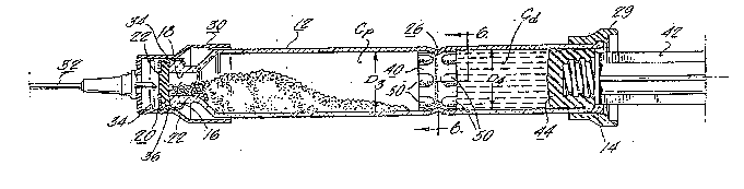
which as illustrated in Figs. 1 and 2 comprises an elongated hollow syringe band or body
12 usually made of glass open at its inner end as at 14 and having a reduced finish 16 at
its forward end. The discharge opening 18 is normally sealed by a conventional circular
disk-type seal 20 made of a flexible, puncturable m~tPr1~l, such as rubber, supported in
place over the discharge opening 18 by an aluminum seal 22 which is crimped over the
finish to hold the seal 20 in place. The aluminum seal 22 has a central opening 22 in its
end face to permit puncturing the disk seal 20 when it is desired to activate the syringe and
dispense the contents. The assembly further includes a cup shaped needle hub 30 which
mounts double ended needle 32. The outer end 32" of the needle 32 is covered by a
needle sheath 38 and is normally seated on the discharge end of the syringe barrel 12 in
the position shown in Fig. 2 with the inner sharp end 32b of the needle 32 spaced from the
disk seal 20. The needle hub 30 has a pair of spaced circumferentially extending ribs 34
which engage in a groove 36 in the aluminum seal or cap 22 holding the needle hub 30
in an unarmed position, as shown in Fig. 2 or an armed position as shown in Fig. 7a.
The syringe barrel 12, in the present instance, is divided into a powder medicament
colllyallment Cp and a diluent compartment Cd by a by-pass stopper 40 frictionally held
2 o by means of a circumferentially extending inwardly directed bead 26 formed in the syringe
~1'7g~31U
body 12. The by-pass stopper seals the compartments Cp and Cd from one another as
explained in more detail hereafter. The stopper is made of an elastomeric material, such
as a rubber compound conventionally used for forming plunger tips and seals in syringes,
and, as will be understood by one of ordinary skill in the art, made from a formulation
5 which the pharmaceutical manufacturer knows is compatible with the medicament and
diluent.
The syringe assembly further includes a plunger rod 42 which threadedly mounts
a discharge plunger 44 which engages in the inner end of the syringe barrel. A
conventional finger grip 29 is mounted on the inner end of the syringe barrel and defines
10 a stop or limit for the discharge plunger 44.
Considering now briefly readying the syringe for use, the needle cup 30 is pushed
inwardly C~llsing the inner sharp end 32a of needle 32 to pierce stopper 20, providing an
air path between medicament chamber Cp and ambient environment. The plunger rod 42
may then be pressed inwardly to displace the discharge plunger 44 forwardly to create a
15 displacement force on the rear face of the by-pass stopper 40 to displace it slightly to the
posltion shown in Fig. A and create flow channels permitting flow of diluent into the
powder medicament chamber Cp. After all of the diluent has been evacuated, the contents
are mixed in the forward chamber Cp and the medicament product is ready for injection.
The contents can be dispensed by forward movement of the discharge plunger in the
20 manner shown in Figs. 7d and 7e until the contents have been fully charged. When the
medicament has been fully discharged the plunger rod n terminal end sets in the flnger
703i~`
grip 30 the needle cup 30 may then be removed from the syringe body and inserted in the
plunger rod 42, providing a~safe throw away package.
Considering now more specifically the by-pass stopper 40, the stopper as best
shown in Figs. 3 and Figs. 4-6 inclusive comprises a series of axially extending,
5 circumferentially spaced projections 50 which in the present instance are arranged in two
axially spaced rows Rl and R2 to define a generally cylindrical sealing surface 46 between
the rows R, and R2 of projections. The sealing surface 46 is preferably of a diameter D,
greater then the diameter D2 of the radially inwardly circumferentially extending bead 26
de~nin~ the separation point between the powder and diluent chambers. The diameter Dl
10 of the sealing surface 46 is also preferably less then the diameters D3 and D1 of the powder
and diluent chambers Cp and Cd which in the preferred form are of the same diameter.
A circular trace through the apex of the ribs is of a diameter D5 greater then the diameter
of the D2 of circumferential bead 26 so that when the by-pass stopper 40 is displaced to
the position shown in Fig. 7a during the initial activation of the discharge plunger, flow
15 passageways P form between the ribs 50 as shown in Fig. 7a to permit diluent to flow
from the diluent compartment Cp to the powder compa. l,~,ent Cp. Further, the diametral
relationships and materials of the by-pass stopper 40 and barrel 12 are such that the
frictional force holding the by-pass stopper in the position in Fig. 7a is greater then the
hydraulic force on the back face of the by-pass stopper 40 during the displacement stroke
2 o of the discharge plunger 44. In this manner, all of the diluent is evacuated to the powder
chamber Cp with the by-pass stopper in a static position until the discharge plunger 44
abuts the rear face of the by-pass stopper 40 in the manner shown in Fig. 7c. The by-pass
~1703 i 0
stopper 40 is then pushed beyond the circumferential bead 26 during the medicament
discharged stroke and rides in front of the discharge plunger 44 in the manner shown in
Fig. 7d and 7e.
There is shown in Figs. 8-lO inclusive another embodiment of by-pass stopper 60
5 in accordance with the present invention. This by-pass stopper 60 functions in the same
manner to the by-pass stopper previously described in that it provides a seal between the
powder chamber and diluent chamber Cp and Cd and upon displacement creates flow
channels for mixing the diluent and powder meclic~ment in the forward chamber. In the
present instance, the by-pass stopper has a generally cylindrical forward or nose portion
62, the outer periphery of which defines a sealing surface 64 having a diameter D8 slightly
greater then the diameter D2 of the circumferentially extending inwardly directed bead 26.
A single row R~ of circumferentially spaced, axially extending ribs 66 are provided on the
outer peripheral surface which are of generally arcuate shape in cross section as shown in
Fig. 9 and define therebetween a series of axial flow passages Pf. The sealing surface 64
15 is preferably of a diameter slightly less than the diameter of the powder medicament and
the diluent chambers Cp and Cd to facilitate flow between the chambers when the by-pass
stopper 60 is initially displaced and also to facilitate retention of the by-pass stopper 60
in the partially displaced position shown in Figs. 11a, 11b and l1c. In the present
instance, the front face 68 of the by-pass stopper 60 is conically shaped and forms an angle
20 of about 15 to the axis of the plunger. The by-pass stopper 60 is particularly suited for
very fine powder medicament products which tend to produce a frosted look to the stopper
when the double row by-pass stopper 40 is used with fine powder medicaments. The fine
2:~70310
powder tends to infiltrate between the projections 50 in the spaces P formed between the
by-pass stopper sealing sur~ace 46 and the inner wall of the chamber Cp creating an
undesirable frosted look, which the user may attribute to diluent leakage. The modified
by-pass stopper 60 tends to keep powder or lyophilization dust out of the region between
5 the stopper and the barrel.
Even though particular embodiments of the present invention have been illustrated
and described herein, it is not intended to limit the invention and changes and
modifications may be made therein with the scope of the following claims.
14