Note : Les descriptions sont présentées dans la langue officielle dans laquelle elles ont été soumises.
CA 02170338 2004-09-08
HEATED MIRROR
FIELD OF THE INVENTION
This invention relates to a heated mirror, in particular an exterior mirror
for a
motor vehicle, of the type having an electrical heating element in thermal
contact with
the mirror and at least one temperature sensor, which acts in combination with
a
thermostatic switch for the electrical heating element.
REVIEW OF THE ART
Heated mirrors of this type are already in use as exterior mirrors for motor
vehicles. With most such mirrors, the rear surface of the mirror, on which the
mirror
coating has been vapour deposited, is connected to resistance heating elements
in the
shape of strips, which elements are manually and/or thermostatically
controlled.
IS
It should not be necessary to heat a mirror located in the open air, or rather
the
exterior mirror of a motor vehicle, unless the temperature of the mirror
surface falls
below the dew-point of the surrounding air, or if it can no longer fulfil its
function
properly because its surface is fogged up or it is covered with ice or snow.
The main
reason why such mirrors located in the open air become unusable is an
increased
humidity which precipitates as condensation on the mirror surface.
It is known to provide controls for windshield wipers which are activated by
the detection of moisture, and demisters for interior glass windows which are
activated by moisture detectors, but to the best of my knowledge no such
device has
been proposed for external mirrors for vehicles. Additionally, the moisture
detecting
devices utilized in prior proposals have been located on a portion of the
inside of the
glass separate from that treated by the demister, an arrangement which would
not be
very practical within the limited area of a vehicle mirror, since not only
211033
is the moisture detecting element on the inside of the
glass, but it obscures part of the window, and, in order to
permit it to detect misting conditions, that part of the
window will not be heated.
SUMMARY OF THE INVENTION
The present invention provides a heated exterior
mirror for motor vehicles comprises a mirror glass with a
reflecting coating deposited on a rear surface thereof; a
transparent conductive coating on a front surface of the
mirror glass, divided into at least two zones by a narrow
non-conductive gap; an electrical heating element thermally
bonded to a rear surface of the mirror glass behind the
reflective coating; a circuit connected between two zones
of the transparent conductive coating to sense changes at
least one of the capacitance and resistance of the gap due
to deposition of moisture on said front surface and
providing an output indicative of the presence of moisture;
and switching means receiving said output and switching
power to said electrical heating element responsive to the
detection of moisture on such front surface. The division
of the transparent, conductive coating on the front
surface, into at least two areas separated electrically
from one another, creates boundary surfaces between
electrically conductive areas which are opposite to one
another and insulated from one another, so that it is
possible to utilize the coating as a resistive and/or
capacitative humidity sensor. The insulation resistance
between the areas which are electrically insulated from one
another is considerably reduced by condensing moisture, so
that a reduction in the resistance value (and/or increase
in capacitance) indicates that the mirror has fogged up,
signalling in turn that it is necessary to heat the mirror.
In principle, such a fogging-up of a mirror can occur at
almost any temperature because it merely requires that the
mirror, due to external conditions, is cooler than the dew-
point of the ambient air. The separate connections to the
2
217338
areas separated electrically from one another by a narrow
elongated gap allow the state of a substantial portion of
the mirror surface to be monitored by an appropriate
circuit arrangement, the changing value of the electrical
resistance as well as of the capacitance of the layer
allowing an effective humidity sensor to be produced.
The application of a conductive, transparent coating
to the front surface of the mirror allows inexpensive and
simple manufacture of a humidity sensor, which is
integrated into the mirror itself and whose signals can be
connected directly to a circuit controlling the heating
element. In an especially advantageous embodiment the
mirror is designed to that the heating may be turned on
either in accordance with the resistance or capacitance
between the electrically conductive areas on the front
mirror surface in response to moisture or in accordance
with signals from a temperature sensor, the sensing of
moisture causing the element to turn on even when the
temperature sensor does not indicate that the temperature
has fallen below a preset threshold. Taking into account
that fogging-up of the mirror is the primary reason for
activating the mirror heating system, it makes sense to
switch on the mirror heating in response to fogging-up of
the mirror resulting from the condensation of moisture.
In order to heat the mirror surface as quickly as
possible, it is necessary to keep the masses to be heated
low and to ensure that heat reaches mainly the mirror glass
and not other areas, for example, a mirror housing or the
ambient air. This is favoured by forming the electrical
heating elements as a surface coating of electrically
conductive material applied to the rear surface of the
mirror: such a surface coating can be made thin and,
therefore of low mass. Preferably such surface coating of
electrically conductive material forming the heating
elements, as well as the conductive, transparent coating of
3
21705~~
.'. the front surface are applied in a plasma process, in
particular by arc atomization or in a thin-film coating
process.
By using the arc atomization or the thin-film coating
process, metallic conductors can be applied directly to the
mirror glass as a film of a few Angstrom units or a few
microns in thickness without an intermediate layer of
adhesive or other adhesion-increasing substances, which in
turn reduces the mass to be heated, making possible
particularly quick heating. This also reduces considerably
the energy required to heat the mirror compared to known
systems.
In accordance with another preferred feature, the
switch used for the heating elements is a semiconductor
switch, such as a power transistor, whose heat sink is
thermally bonded to the mirror. Thus heat losses resulting
during the switching process are recovered in a useful
manner so that energy consumption is reduced.
The transparent, conductive coating used to make the
humidity sensor can be formed in a simple manner as a
chromium layer, plasma etching (for example) being used to
produce the division into areas separated electrically from
one another. Such an etching process with a suitably thin,
transparent, conductive coating allows the width of the gap
produced by etching to be regulated exactly, which is
particularly advantageous both in setting the capacitance
of the coating and in obtaining reproducible results in
resistance measurement. In addition, such a coating and
etching have the advantage of being essentially invisible,
so that the mirror continues to function without
impairment.
In order to ensure that the heating system can
reliably prevent the mirror from fogging up at all external
4
2i 7338
temperatures likely to be encountered, the mirror is
preferably designed in such a way that the heating capacity
of the heating element is regulated so that their surface
temperature remains below 200°C, preferably below 150°C.
In order to achieve even quicker distribution of heat in
those areas in which moisture condenses, the mirror may be
constructed with an additional separate heating element
provided on the same side of the mirror as the electrically
conductive coating, although it should be arranged so as
not to reduce significantly the functionality of the
mirror.
The invention is explained in more detail below with
reference to a specific embodiment.
SHORT DESCRIPTION OF THE DRAWINGS
IN THE DRAWINGS:
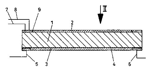
Fig. 1 is a cross-section through a mirror element of
a vehicle exterior mirror;
Fig. 2 is a plan view of the external surface of the
mirror from the direction of arrow II in Fig. 1; and
Fig. 3 is a block diagram of a control circuit.
DESCRIPTION OF THE PREFERRED EMBODIMENT
Fig. 1 shows a mirror glass 1 on which a transparent,
conductive chromium coating 2 is applied to the front
surface by means of arc atomization. A conductive coating,
forming a heating element 4, is applied to the rear surface
of the specular reflective coating 3 applied to the mirror
glass. Connections 5 and 6 are provided for the heating
element 4 , whereas connections 7 and 8 , made to areas of
the coating 2 electrically separated from one another by an
etched gap 9. An additional heating element may be
provided on the front surface of the mirror, for example
around its periphery as shown at 18.
The front surface of the mirror, which acts as a
5
217~33~
.~" humidity sensor, is shown in more detail in Fig. 2. The
coating 2 is sub-divided into areas insulated electrically
from one another by the etched gap 9. When moisture
condenses on the front surface, the gap 9 is bridged by a
thin film of water, which reduces the resistance value
between the conductors 7 and 8. In an analogous manner the
capacity between these two conductors also changes because
of the high dielectric constant of water. These changes
are detected by the circuit of Figure 3, as described
below.
Referring to Figure 3, an oscillator 10 generates a
high frequency electrical signal which is applied to the
connection 8 through a capacitor 11, and the contact 7 is
connected through a capacitor 12 to an envelope detector
13, the output of which is applied to a trigger circuit 14,
the output of which is in turn applied, together with that
of a temperature sensing circuit trigger circuit 15
employing a thermistor, to an OR gate 16. The output of
gate 16 controls an electronic switch 17, for example a
field effect power transistor, which completes a circuit
through the connections 5 and 6 and the heating element 4.
Conveniently the oscillator 10, the trigger circuits and
the OR gate are implemented utilizing a quadruple 2-input
NAND Schmitt trigger chip such as is available from RCA and
other manufacturers under the number 40938. The built-in
hysteresis of such triggers permits them to be used to
implement oscillators, and to implement trigger circuits
with threshold hysteresis, as well as performing normal
NAND or OR logic functions.
In the present case, and in the absence of
condensation or other moisture, the capacitance between the
connections 7 and 8 will be low and the resistance very
high. Insufficient signal will therefore reach the
detector 13 from the oscillator to provide an output above
the turn-on threshold of the circuit 15; in fact this
6
2170338
'- output should also be below the turn-off threshold. As
condensation builds up on the etching 9, the capacity
between the connections 7 and 8 will increase and the
resistance will decrease. The resistance effect will be
influenced by the presence of contaminants on the mirror
surface or in the moisture, but this will not significantly
alter the capacitance effect so that a substantial increase
in signal transfer to the detector can be relied up as
moisture builds up. Component values are selected so that
any substantial increase in signal transfer will provide a
detector output sufficient to exceed the turn-on threshold
of the circuit 14, thus turning on the heating element.
The circuit 14 will not turn off until the detector output
falls below the turn-off threshold of the circuit 14, and
this in conjunction with the thermal inertia of the mirror,
should ensure that it is fully demisted. The circuit 15,
which is optional, is set up so that the element 4 will be
turned on when the temperature, as sensed by a thermistor,
falls below a predetermined threshold, and turned off when
it rises above a somewhat higher threshold, thus also
providing thermostatic control of the element 4. The
circuit 15 will however operate in the presence of fogging
to turn on the element 4, even if the ambient temperature
has not fallen below the turn-on threshold of circuit 15.
Alternatively, a thermistor controlled trigger circuit
may be arranged to override the signal from the moisture
detecting circuit when the temperature of the mirror rises
to a level at which condensation is unlikely, thus avoiding
;unnecessary heating of the mirror should the moisture
sensing circuit malfunction, for example because of
excessive conductive contaminants on the mirror.
The etching 9 may have a width of, for example, 10
microns, and should therefore be substantially invisible.
A current of 1.8 amperes at 12 volts, which is readily
controlled by a power transistor forming switch 17, will
7
2170338
provide sufficient heating capacity for typical external
mirror. A heat sink 9 of the power transistor forms switch
17 may advantageously be bonded to the element 41 as seen
in Fig. 1 so that any heat generated in the transistor is
not wasted.
Preferably the specular coating 3 on the back of the
mirror is also a chrome coating, or other infrared
reflective coating. This specular coating, as well as
acting to reflect light impingent on the mirror, also acts
to reflect infrared radiation produced by the heating
element 4 back into the element 4 where it is reabsorbed
and speeds heating of the element such that conductive
transfer of heat into the mirror is enhanced while loss of
energy due to infrared transmission through the glass is
reduced.
8