Note : Les descriptions sont présentées dans la langue officielle dans laquelle elles ont été soumises.
~7(~45~
Guide Bar having an Oil-Feed Channel
Field of the Invention
The invention relates to a guide bar for a saw chain and
has a sword-shaped base body defining a peripheral surface. A
guide groove is formed in the peripheral surface to guide the
saw chain in its movement about the guide bar. An oil-feed
channel opens into the guide groove in the region of the
groove bottom.
Background of the Invention
Such a guide bar is clamped to a portable handheld
motor-driven chain saw and is clamped between the sprocket
wheel cover and the motor housing. The guide bar can be
mounted to a tree harvesting machine, a so-called harvester
machine, by means of a clamping plate.
Lubricating oil is introduced into the guide groove
formed in the periphery of the guide bar for the saw chain.
The lubricating oil enters via an oil-feed channel opening
into the guide groove in the region of the groove bottom. The
oil-feed channel is fed from a transverse channel lying below
the groove bottom. This transverse channel has at least one
entry opening on an outer side of the guide bar.
The configuration of the oil-feed channel as well as the
transverse channel is costly with respect to both time and
work especially for those guide bars made of solid material.
Because the material of the guide bar is hardened, special
drilling tools or special methods, such as eroding or laser
techniques or the like, are necessary for making the channels.
The transverse channel is relatively simple to make as a
through bore extending perpendicularly to the guide bar.
However, introducing the oil-feed channel is hindered because
of the width of the guide groove. Accordingly, the oil-feed
channel cannot be greater in diameter than the width of the
217~45~
guide groove because it must be bored or eroded from the
periphery parallel to the plane of the guide bar. If the
oil-feed channel would be configured to have a diameter
greater than the width of the guide groove, then the guide
flanges of the guide groove would also be eroded or removed
because the tool runs up against the inner side of the guide
flanges. Even partially abrading the guide groove to a
greater depth is unsatisfactory since the strength of the
guide flanges is reduced thereby. The introduction of the oil
channels is greatly limited by the configuration of the oil
channels as well as by the position thereof.
Summary of the Invention
It is an object of the invention to configure a guide bar
in such a manner that the oil channels to be provided can be
substantially freely selected with respect to position, form
and size and yet be easy to manufacture.
The guide bar of the invention is for guiding a saw
chain. The guide bar includes: a sword-shaped base body
having a peripheral edge defining a peripherally-extending
guide groove for guiding the saw chain in its movement around
the guide bar; the guide groove having a groove bottom; the
base body having first and second lateral sides and a cutout
formed therein; the cutout being formed in the base body so as
to be open at least at one of the lateral sides and so as to
extend essentially below the groove bottom; an insert part
separate from the base body seated in the cutout; the insert
body having a transverse channel formed therein through which
oil is supplied and the transverse channel being disposed
below the groove bottom; and, the insert body delimiting an
oil-feed channel extending from the transverse channel and
opening into the guide groove in the region of the groove
bottom whereby the oil passes from the transverse channel to
21~0~5~
the guide groove through the oil-feed channel.
With the arrangement of the insert part, an otherwise
unattainable freedom of configuration is obtained with respect
to the position, the form and the size of the oil-feed channel
as well as also the feeding transverse channel. The machining
complexity for an appropriate cutout in the guide bar and the
complexity of assembly of the insert part in a corresponding
cutout are minimal.
The cutout can be configured as a breakthrough or also as
a recess or a portion which has been ground out. The insert
part is, in each case, selected to have an appropriate
thickness. If the thickness of the insert part is greater
than the depth of the cutout, then the insert part is pressed
perpendicularly to the guide bar when the end of the guide bar
having the insert part is clamped between the support and the
clamping plate. In this way, a tight connection of the
transverse channel to the oil-feed channel of a lubricating
pump of the drive unit is obtained in the plane of contact.
Preferably, the oil-feed channel is formed in the insert part
itself. The diameter of the oil-feed channel can then be
configured to be greater than the width of the guide groove.
The pump action can be effected in a targeted manner with
a change of the cross section in the flow direction of the
oil-feed channel. The oil-feed channel can be inclined in the
direction of the movement of the saw chain.
In a special embodiment of the invention, the cutout is
configured to have an undercut in at least one of the side
surfaces into which the insert part can be pressed. The
insert part is provided with a raised portion which engages
into the undercut. The insert part is preferably made of
plastic. In this way, a form-tight interdigital engagement is
guaranteed whereby the insert part is held so that it cannot
~17~5~
become separated.
It can be adequate to configure the insert part with a
slightly greater dimension than the cutout so that the insert
part can be held force-tight in the cutout. Preferably, an
undercut as well as an oversize is provided.
The insert part is purposefully made as one piece with
fill bodies arranged in the guide groove. In this way, the
fill bodies delimit a retaining space lying in the region of
the output opening of the oil-feed channel.
Preferably, the insert part is made of a material
different from that of the base body. The insert part can
especially be a plastic part made of an elastomer, a silicone
mixture or rubber. A metal die cast part made of aluminum or
like material is also purposeful. In this way, the
corresponding channels are formed at the same time that the
insert part is produced.
Brief Description of the Drawings
The invention will now be described with reference to the
drawings wherein:
FIG. 1 is a schematic view, partially in section, of a
motor-driven chain saw having a guide bar according to the
invention;
FIG. 2 is an enlarged detail view of the guide bar of
FIG. 1 with a mounted insert parti
FIG. 3 is a section view taken along line III-III of
FIG. 2i
FIG. 4 is an enlarged view of a rectangular insert part
in a guide bar;
FIG. 5 is an enlarged detail view of a disc-shaped insert
part in a guide bar;
FIG. 6 is an enlarged detail view of a rectangular insert
part having a constricted region and mounted in a guide bar;
217~55
FIG. 7 is an enlarged detail view of a
rectangularly-shaped insert part having semicircularly-shaped
rounded narrow ends and a transverse channel having an opening
only to one side of the base bodyi
FIG. 8 is a section view taken along line VIII-VIII of
FIG. 7;
FIG. 9 is an enlarged detail view of a closure-cover like
insert part for a recess formed in the guide bar;
FIG. 10 is a section view taken along line X-X of FIG. 9;
FIG. lOa is a section view corresponding to FIG. 10 with
a transverse channel for supplying oil with the transverse
channel extended in the base body;
FIG. 11 is an enlarged detail view of a closure cover
like insert part of another embodiment;
FIG. 12 is a section view taken along line XII-XII of
FIG. 11;
FIG. 13 is an enlarged detail view of an insert part
pressed into an undercut cutout;
FIG. 14 is a section view taken along line XIV-XIV of
FIG. 13;
FIG. 15 is an insert part having an undercut and a head
extension projecting into the guide groove;
FIG. 16 is a section view taken along line XVI-XVI of
FIG. 15;
FIG. 17 is a rectangularly-shaped insert part having a
head extension engaging in the guide groove;
FIG. 18 is a section view taken along the
line XVIII-XVIII of FIG. 17;
FIG. 19 is an enlarged detail view of an insert part
configured as one piece with fill bodies mounted in the guide
groove;
FIG. 20 is a section view taken along line XX-XX of
~170~55
FIG. 19;
FIG. 21 is an enlarged detail view of an insert part
having two oil-feed channelsi
FIG. 22 is a section view taken along line XXII-XXII of
FIG. 21;
FIG. 23 is a detail view of an insert part configured as
an enclosure defining a hollow profile and being mounted in a
guide bar;
FIG. 24 is a section view taken along line XXIV-XXIV of
FIG. 23;
FIG. 25 is an enlarged detail view of an insert part
inclined in the running direction of the saw chain and having
a tapered oil-feed channel;
FIG. 26 is a section view taken along line XXVI-XXVI of
FIG. 25;
FIG. 27 is a section view taken through a further insert
part having a transverse channel and an oil-feed channel; and,
FIG. 28 is a section view taken along line XXVIII-XXVIII
of FIG. 27.
Description of the Preferred Embodiments of the Invention
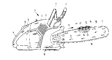
The guide bar 9 of the invention for a saw chain 10 is
mounted on a motor-driven chain saw 1 in the embodiment shown.
A guide bar of this type is mostly provided on a
tree-harvesting machine (a so-called harvester machine). A
clamping end of the guide bar is mounted with a clamping plate
on a support of the machine. The guide bar comprises a
sword-shaped base body 16 having a periphery 17 in which a
peripheral groove 11 is introduced for guiding the saw
chain 10. The peripheral surfaces (17.1, 17.2) shown in
FIG. 3 remain at the two sides of the guide groove 11 and
define guide surfaces for the side cutting links 12 and side
connecting links 14 of the saw chain 10. The drive links 13
21 7~55
connect the cutting links 12 and the connecting links 14 and
have rakers projecting into the guide groove 11. The drive
links 13 coact with a sprocket wheel driven by an internal
combustion engine 3 in order to drive the saw chain 10 in the
running direction 15.
The motor-driven chain saw 1 shown as an example is held
by an operator at a rearward handle 4 aligned in the
longitudinal direction of the guide bar 9 and a forward
handle 7 extending transversely above the engine housing 2.
The throttle lever 5 and a throttle lever lock 6 corresponding
thereto are mounted in the rearward handle 4. A guard lever 8
is provided between the forward handle 7 and the guide bar 9.
The guard lever 8 is at the same time a trigger for a safety
braking device for bringing the saw chain 10 to standstill.
The end of the guide bar 9 facing toward the motor-driven
chain saw 1 is tightly clamped in the embodiment between a
sprocket wheel cover 18 and the engine housing 2. Oil-inlet
openings 20 are provided in the base body 16 of the guide
bar 9 in the region of the clamping end. The oil-inlet
openings 20 are formed by a transverse channel 21 (FIG. 3)
arranged in the guide bar 9. The transverse channel 21
commlln;cates with an oil-feed channel 22 which opens into the
guide groove 11. The oil-feed channel 22 preferably branches
approximately at right angles from the transverse channel 21
and runs especially perpendicularly to the groove bottom 23 of
the guide groove 11.
- An oil pump (not shown) pumps lubricating means into the
guide groove 11 via the oil-inlet opening 20, the transverse
channel 21 and the oil-feed channel 22. The lubricating means
is taken along by the rakers of the drive links 13 and is
distributed over the chain itself because of centrifugal force
when the saw chain is running in the peripheral direction 15
2~71)~55
and lubricates the connecting joints of the saw chain as well
as the guide surfaces (17.1, 17.2) on the guide
flanges (11.1, 11.2) of the guide groove 11. Wear is reduced
and excellent quiet running is obtained because of the
lubrication of the saw chain and the running surfaces on the
guide bar 9.
As shown in FIGS. 2 and 3, the transverse channel 21 and
the oil-feed channel 22 are provided in an insert part 25
configured separately from the base body 16 of the guide
bar 9. The insert part 25 is seated in a corresponding
cutout 24 of the guide bar 9. The cutout 24 can be configured
as a breakthrough (FIG. 3) which is open to both outer
sides (9.1, 9.2) of the guide bar 9.
Referring to FIG. 2, the cutout 24 extends essentially
below the groove bottom 23 of the guide groove 11 and is open
to the guide groove. The thickness (d) of the insert part 25
corresponds essentially to the depth (t) of the cutout 24.
The thickness (d) is preferably slightly greater than the
depth (t) of the cutout 24 whereby a projecting amount (u) of
the insert part 25 results at both outer sides (9.1, 9.2) of
the guide bar 9. The breakout is cut out especially by means
of a laser.
The insert part 25 is made of another material than the
guide bar 9 comprising especially a solid material. The
insert part 25 preferably is a plastic part (elastomer,
silicone mixture, rubber) or a metal die cast part (aluminum,
magnesium). Because of the projecting amount (u), the insert
part 25 is swaged when the rearward end of the guide bar is
clamped between a support (for example, the engine housing 2)
and a clamping plate (such as the sprocket wheel cover 18).
This causes the insert part 25 to provide a liquid-tight seal.
A seal-tight connection of the oil-inlet opening 20 to the
217~55
lubricating oil supply is ensured.
The insert part 25 is preferably provided with exterior
dimensions which exceed those of the cutout 24 so that the
insert part 25 is swaged when pressed into the cutout 24 in
the plane of the guide bar 9. In this way, a tight,
non-separable seat of the insert part 25 is provided in the
cutout 24 of the guide bar 9.
As shown in FIG. 2, the cutout 24 extends into the guide
groove 11 so that the oil-feed channel 22 formed in the insert
part 25 opens directly into the guide groove 11 and preferably
above the groove bottom 23. For this purpose, the insert
part 25 preferably projects into the guide groove 11. In the
longitudinal direction of the guide groove 11, filler
bodies (19.1, 19.2) are provided in the guide groove 11
forward and rearward of the insert part 25 in order to retain
the lubricating oil, which exits into the guide groove 11, in
the region of the outlet opening of the oil-feed channel 22.
The filler bodies delimit a retaining space 19.3 in which the
oil-feed channel 22 opens. The oil-feed channel 22 expands in
a slightly funnel-like shape in the direction toward its
opening. This funnel-like shape is preferably conical.
The form of the insert part 25 corresponds to the
cutout 24 itself. In the embodiments of FIGS. 2 to 5, the
transverse channel 21 formed in the insert part 25 is open to
both outer sides (9.1, 9.2) of the guide bar 9. The cross
section of the oil-feed channel 22 corresponds approximately
to a flattened circle. Preferably, the insert part 25 is
configured symmetrically to a longitudinal center plane 29 of
the guide bar 9. A configuration unsymmetrical to this plane
can be purposeful (FIGS. 9 to 12).
The basic form of the insert part 25 comprises a
parallelopiped-shaped base body such as shown in FIG. 4. Such
70~
a parallelopiped-shaped base body having rectangular flat
sides can have a constriction at half length as shown in
FIG. 6. Preferably, the base body has rounded narrow ends in
the peripheral direction (FIG. 2). Preferably, the narrow
ends are formed as semicircles. In a further embodiment of
FIG. 5, the insert part 25 can have the form of circular disc.
In the embodiment of FIGS. 7 and 8, the transverse
channel 21 is configured as a blind channel starting from one
outer side 9.2 of the guide bar 9. The oil-feed channel 22
branches off from the transverse channel 21 to the guide
groove 11. It is noted that the insert part 25 is otherwise
configured in correspondence to the embodiment of FIGS. 2
and 3.
In the embodiment of FIGS. 9 and 10, the cutout 24 is
formed as a spotfaced recess having a depth (t) greater than
the half thickness D but less than the thickness D of the
guide bar 9. The recess 24 formed as a spotfaced recess is
machined, preferably by milling, from the outer side 9.2 of
the guide bar 9. On the side which faces toward the recess,
the insert part 25 has a peripheral edge 26 which is open
toward the guide groove 11. The peripheral edge 26 delimits
the oil-feed channel 22. This channel is formed between the
insert part 25 and the base 27 of the recess 24. The
transverse channel 21 is formed in the insert part 25. In
this way, an oil-inlet opening 20 provided on the insert
part 25 is present only on the outer side 9.2.
In the embodiment of FIG. 10a, an oil-inlet opening 20 is
provided on both outer sides 9.1 and 9.2 of the guide bar 9.
The insert part 25 is configured identically to the embodiment
of FIG. 10. The transverse channel 21 comprises a first
segment 21.1 formed in the insert part 25 and a second
segment 21.2 configured to be on the same axis as the
~170~S~
segment 21.1. The segment 21.2 is formed in the base body 16
of the guide bar 9. It can be purposeful to configure the
diameter of the segment 21.2 of the transverse channel 21 to
be slightly greater than the diameter of the segment 21.1 in
the insert part 25. The segment 21.2 is formed in the guide
bar 9.
In the embodiment of FIGS. 11 and 12, the insert part 25
is configured as a closure plate of a spotfaced recess
introduced from the outer side 9.2. The depth of the
cutout 24 corresponds approximately to the flange width (b) of
a guide flange 11.2 of the guide groove 11. Otherwise, the
configuration corresponds to the embodiment of FIG. 10a.
The embodiment of FIGS. 13 and 14 corresponds with
respect to its basic configuration to the embodiment shown in
FIGS. 2 and 3. The embodiment of FIGS. 13 and 14 departs from
that shown in FIGS. 2 and 3 in that the cutout 24, which is
configured as a breakthrough, is provided with an undercut 28
having a depth (h). The undercut preferably extends
peripherally and lies approximately symmetrically to the
longitudinal center plane 29 of the base body 16 of the guide
bar 9. The insert part 25, which is configured in
correspondence to the cutout, engages with its increased
peripheral edge 30 in the undercut 28 whereby the insert
part 25 is held form-locked in the base body 16
perpendicularly to the plane of the guide bar 9.
It can be purposeful to arrange the undercut only on
mutually opposite sides of the rectangularly-shaped base body
of the insert part 25 as shown in FIGS. 15 and 16. The insert
part includes a head extension 31 at its end facing toward the
guide groove 11. The head extension 31 preferably engages
force-tight between the side flanges (11.1, 11.2) of the guide
groove 11. A raised edge 30 is provided on the end lying
2170~55
opposite to the head extension 31 and corresponds to that
shown in the embodiment of FIGS. 13 and 14. The raised
edge 30 engages in an undercut 28 machined into the side
surface of the cutout 24. The undercut 28 is symmetrical to
the longitudinal center plane 29 of the base body 16 of the
guide bar 9.
In the embodiment of FIGS. 17 and 18, a head extension 31
is provided exclusively on the end of the insert part 25
facing toward the guide groove 11. The head extension 31
engages force-tight between the side flanges (11.1, 11.2) of
the guide groove 11. The arrangement of such a head
extension 31 ensures already that the insert part 25 will be
securely held even when the insert part is not configured so
as to have an oversize or when the insert part 25 shrinks
because of deterioration of the plastic, silicone mixture or
rubber.
In the embodiment of FIGS. 19 and 20, the insert part 25
is configured essentially as in the embodiment of FIGS. 2
and 3 and is one piece with the fill bodies (19.1, 19. 2). A
retaining space 19.3 is provided between the fill bodies and
is configured as a depression between the fill bodies. The
thickness of the fill bodies (19.1, 19.2) corresponds
preferably to the thickness of the insert part 25.
In the embodiment of FIGS. 21 and 22, the insert part 25
extends over a longitudinal segment of the guide groove 11.
The insert part has an oil-feed channel 22.1 which lies
inclined to the running direction 15 of the saw chain. A
further oil-feed channel 22 is arranged next to the oil-feed
channel 22.1. The oil-feed channel 22 opens into the guide
groove 11 essentially at right angles. In the embodiment of
FIGS. 21 and 22, the insert part 25 has approximately the form
of a right triangle having different side lengths.
- 217~55
The embodiment of FIGS. 23 and 24 shows an insert part 25
configured as a box-like hollow profile 32. This hollow
profile 32 opens into the guide groove 11 of the guide bar 9
at the opposite ends. The hollow profile 32 is configured to
have essentially a U-shape. The U-shape lies symmetrically to
the longitudinal center axis 33 of the guide bar 9. The free
legs of the U-shaped profile 32 are bent in the direction
toward the guide groove 11 and open between the fill
bodies (19.1, 19.2) in the guide groove 11.
In the embodiment of FIGS. 25 and 26, the insert part
itself is inclined in the running direction 15 of the saw
chain. Preferably, the insert part has a
longitudinally-extended oil-feed channel 22 which is tapered
and especially conically tapered. The opening of the oil-feed
channel 22 is above the groove bottom 23 and has a diameter
less than the width B of the guide groove 11. Because of the
arrangement in the insert part 25, the transverse channel and
the oil-feed channel can be configured with different cross
sections which are adapted to the particular operating
conditions.
Preferably, the oil-feed channel 22 is configured to have
a diameter greater than the width B of the guide groove 11 as
shown in FIGS. 2 to 8.
In the embodiment of FIGS. 27 and 28, the base body of
the insert part 25 has essentially a rectangular shape. The
insert part 25 comprises a half-cylindrical foot portion 40
and a head extension 41 extending on the flat side. The head
extension 41 is tapered toward its free end 42. The
longitudinal center axis 43 of the transverse channel 21 is
coincident to the circular center point of the foot
portion 40. The longitudinal center axis 29 of the oil-feed
channel 22 lies at right angles to the longitudinal center
2170~55
14
axis 43. The longitudinal center axis 29 also lies in the
symmetry plane 44 of the insert part 25. The narrow sides of
the insert part 25 are configured so as to be rounded in the
peripheral direction. The opening 45 of the oil-feed
channel 22 lies in a plane on which the longitudinal center
axis 29 is preferably perpendicular. The longitudinal
sides 46 of the insert part 25 lie at an angle 47 to the
tangent 48 at the foot portion 40. The peripherally extending
peripheral edge 49 of the insert part 25 is beveled. The
transverse channel 21 and the oil-feed channel 22 are
configured to be cylindrical. The diameter of the transverse
channel 21 is greater than the diameter of the oil-feed
channel.
It is understood that the foregoing description is that
of the preferred embodiments of the invention and that various
changes and modifications may be made thereto without
departing from the spirit and scope of the invention as
defined in the appended claims.