Note : Les descriptions sont présentées dans la langue officielle dans laquelle elles ont été soumises.
WO 96/03849 ~ I 7 0 9 1 l~ PCr/N095/00123
Title: Self-baking carbon electrode.
5 Technical Field
The present invention relates to a self-baking electrode for use in electrical smelling
fi~ S.
Back~round Art
10 Conventional self-baking electrodes comprise a vertical arranged electrode casing
extending through an opening in the furnace roof or hood. The upper end of the electrnde
casing is open in order to allow addition of unbaked carbonaceous elecLI(lde pa.ste whicll
upon heating soften and melts and is thereafter baked into a solid carhon ~lectl ode due ~o
heat evolved in the paste in the area of supply of eleclric opera~ g CUI-I-elll lO lhC
15 electrode. As the electrode is consumed in the furnace the electrode i,~i loweled and new
sections of casing is installed on the top of the electrode column an(l lurlhel unhal;c(l
electrode paste is added.
The conventional electrode of this type is equipped with inner, vel~ical melallic rihs
20 affixed to the inner surface of the electrode casing which rihs extcnd radially towards Ihe
center of the electrode. When a new section of electrode casing is inslalled at lhe top ol
the eleclrode column, the ribs are welded to the ribs in the casing helow hl ordcl to ohlahl
continuous ribs in vertical direction. The ribs serve as a reinforcemell[ ol ~he ha~;e(l
electrode and to conduct electric current and heat radially into ~he eleCLIO(Ie paste durillL!
25 the baking process. To compensate for the consumption of the eleclrode the electl(lde is
lowered downwardly into the furnace hy means of electrode holding and .`ilipr)illg meall.~.
When conventional electrodes of this type are used, the elec~rode ca~ and Ihe inllcl
ribs melt when the electrode is being consumed in the furnace. The mel;ll conle~ll ol' lhc
30 casing and the ribs is thus transferred to the product produced in the smellillg l`urnace. A.
the electrode casing and the inner rihs usually aré made from steel, sucll convellliollal
self-baking electrodes can not be used for electrical smelting furnaces l`or llle ploduclio
of silicon or for the production of ferro-silicon having a high silicoll colllelll~ a.~ lhc ir
content in the produced product will become unacccptably higll.
`aUB~ I I I UTE SHEET
W~96t03849 2~ 9~ P-~r/NOg5/00123 --
Already in the 1920's it was proposed to conduct heat into selt`-haking electrode.s througll
inserts of prebaked carbon bodies in the unbaked electrode paste. Thus in Norwegian
patent No. 45408 it is disclosed a method for production nf selt:baking electrodes Wllels~
prebaked carbon bodies are placed in the peripheri of the electrodes and kept in place hy
5 the unbaked carbon paste. The carbon inserts are not affixed to the electrode casing, hut
are only kept in place by the unbaked electrode paste, and when the electrode is haked, by
the baked electrode paste. In order to keep the carbon inserts in place het'ore, during and
after baking of the electrode paste, it is a necçss~ry that each casing is completely filled
with hot liquid electrode paste when a new length of casing is installed at the ~op ol th~
10 electrode column, as it is only the electrode paste that keep the carhon inserts in plac~
against the inside wall of the casing. Such a method for addinc electrode paste is
unwanted as gases hazardous to health which evolve from the tar/pitch hindel in lh~
electrode paste, will vaporize from the top of the electrode column and will lhell he ~n
unacceptable health hazard to the operators. The carhon inser[s sllowll in th~ Norwegia
15 patent have a ratio between radial length and thickness ol` less ~han 1:2. The c;llho
inserts well therefore conduct heat only a short length inwardly into lhu ~ ctrode pasl~
and thereby make it difficult to obtain complete baking in the c~n~ral par~ ot tll~ elecll ode.
As the carbon inserts according to Norwegian patent no. 454()~ are nol aft'ixed to lhc
casing or to oneanother in vertical direction and in addition hav~ a ratio hetween radial
20 length and thickness of less than 1:2, these carbon inserts will not t'unction in the s;lme
way as the inner ribs which are used in conventional self-haking electl odes. The metllod
according to Norwegian patent No. 4s4n~ has from these reasons no~ l'ound any pl actical
use.
25 I~ has. however, during the years been proposed a numher ol' modil'icatiolls ol'
conventional self-baking carbon electrodes having inner steel rihs in ordel to avoid
cont:-min~tion of silicon produced in the furnace with iron from ~hc h-Oll in the ~asillg ancl
in the ribs.
Thus, in Norwegian patent No. 149451 it is disclosed a self-ha~;itlg el~cllode Whel`C
eléctrode paste contained in a casing having no inner libs, is heing hal;e(l ahove ~h~ r)lacc
where electric operating current for the smelting furnace is supplie-~ lO ~h~ elccll o(le, and
where the electrode casing is removed after baking of the electrodc. hut hel'ore ~llc
electrode has been lowered down to the place where electlic operalinC cul-lelll is sur)r)lied
to the electrode. In this way an electrode having no casing and no hlller r ihs is pl oduced
SUE~-` 111 UTE SHEET
wo 96,03g49 2 1 7 0 9 1 ~ PCr/N095/00123
This kind of electrode has been used in smelting furnaces for the production ot~t;ilicon~
but has the disadvantage compared to conventional prebaked electrodes tllat costly
devices have to be inct~lled for baking of the electrode and for removing the casinC llom
the electrode.
s
In US patent No. 4,692,929 it is disclosed a self-baking electrode for use with electlic
furnaces for production of silicon. The electrode comprises a permanent m~tal casin~
having no internal ribs and a support structure for the electrode complisillg carhon tïhres.
where the electrode paste is baked about the support structure and where the haked
10 electrode is being held by the support structure. This electrode has the disadvantage lhtlt
special holding devices have to be arranged ahove the top of the electrode in older to hold
the electrode by means of the support structure comprising carhon tihre.s. F~u~ n i~ can
be difficult to slip the electrode down through the permanent ca.sing a.s ~h~ electlo(lc i.s
consumed.
lS
In US patent No~ 4,575,~56 it is described a self-baking electlod~ htlVillg tl pellntlllell
casing with no inner ribs, where the electrode paste is being haked ahoul a c~nll ;ll core ol
graphite and where the electrode is being held by the graphi~e cor~. This elec~l ()de ha.~i lhe
same disadvantages as the electrode according to US patent No. 4~(')2~')'()~ and in
20 addition ~he graphite core is subjected to breakage when the electrode is .suhjecled to
radial forces.
The above mentioned methods for production of self-bakin~ electlode havillt~ no innel-
metal ribs all suffer from the disadvantge that they cannot he used tor elec~lod~.~ havill~ a
25 diameter above 1.2 m without a suhstantial increase in th~ propahilily ol hr~akage.
Contrary to this, conventional self-baking electrodes having a dimet~l ol up lill '.() m ale
used.
I~isclosure of Invention
30 Despite the above mentioned methods and apparatuses for ploduc~ioll ol`.s~ hai;inL!
electrodes in order to avoid iron contamination of the product ploduce i hl ll~ mellinc
furnace, there is still a need for a simple and reliable self-haking carholl elec~ d~. whele
the disadvantages of the known electrodes may t)e overcome. Il i.s thu.s all ohj~ct ol lhc
present invention to provide a self-haking carhon electrode l-ainc nO inllel .sl~cl r ih.s~ hu
SUB~IIIUTESHEET
W0 96/03849 2~ Pcr~N095/00123
where the disadvantages of the electrode disclosed in NorweeTian ilal~nt Nc). 454~; ar~
overcome.
Accordingly, the present invention relates to a self-haking carhon elec~lode ploduced in
S direct connection with the furnace wherein it is consumed, which electrode comi?rises an
outer casing made from an electrical conducting material, and having innel radial, ver~ical
ribs and wheré carbonaceous unbaked paste is supplied to the casine~ WhiCIl i?a.~ae i~C heil-e
baked to a solid electrode by means of electric current supplied ~o lhe elec~rode, ~;aid
electrode being characterized in that the inner radial, vertical rihs con~i.s~ ol`.solid carhon
10 sheets being affixed to the inside of the casing, said carhon sheets havinr a ra~io helwee
radial length and thickness of above S: 1.
The carbon sheets can be made from grai?hite or from i?rehaked carhon maleliah an~ may
be reinforced hy carbon fïbres or hy fibres of other materiahs whicil ~vill not ~t~nLamillale
15 the product produced in the smeltine furnace. The ratio hetw~ell r;ldial l~ne~ll and
thickness of the carbon sheets are decided based on the type ol carholl m;lleli~l u.~e(i ;IIld
the strength of the carhon material.
If the carbon sheets are made from prehaked carhon material, the carholl rihs i relerahly
20 have a ratio between radial length and thickness ahove 8:1. If the carhon slleel.~; are made
from graphite, the carhon rihs preferahly have a ratio hetween radial lelletll an(l ~hicklle.
of above 15:1.
According to a preferred embodiment of the present inventinn ~he calholl rihs ale ;Illixed
25 to the casing by means of bolts and/or by glueing.
The casing having carhon ribs are manufactured in suhstantially ~he sam~ way a.~ ~he
casing for self-baking electrodes having steel rihs. Each lenctll ot casinC c.ln lhus he
produced from sections where the total numher of section.s are e(3ual ~o the numhcl ol
30 carbon ribs. Each section of the casing is at least nn one of it.s vellical si(les e~uir~ed
with an inwardly extending flange. When assemhling a mantel lell~tll, ~hc calholl rihs ale
affixed between the vertical flanges on adjacent sections hy mean.~ o~ hol~.s and nul.~i
and/or hy gluing. Alternatively each length of casing can he ~?roduc~ ol ~velde~l cylin~el-
shaped sheets having vertical flanges welded to its inside for aflixine lhc ualholl lihs.
~UE~ i I I UTE SHEET
W096/03849 Z~ 7.D91~5 PCr/NO95/00123
The carbon ribs have a vertical extension which is at least equal to the lenclll ol e;lc~l
length of casing. Preferably pth,e~ carhon rihs have a length which exceeds the leng~ll ol
casing by up till S0 cm. When mounting a new length of caSinc on the lOp Or the
electrode the carbon ribs in the new length of casing will thus overlap Ille carhon rih~s in
5 the length of casing below. When electrode paste is being baked in the alea hetween two
length of casing it is thereby obtained a vertical contact between the calhon rih~s in the
same way as for steel ribs in conventional self-baking electrodes.
In the electrode according to the present invention the ribs made from calholl .shee~s will
10 have a good electrical conductivity and the electric current supplied lo lhe electrode will
be conducted inwardly into the unbaked electrode paste. Thi.s is vely import;~ in or~lel lo
ensure a fast baking of the electrode, for example after an electl ode hre;ll;aëe.
For big electrodes diameters, the ribs are necessary in ordel to .stahili~c ~he C~lll-ell~ alld
lS the heat conditions in the periphery of the electrode. In addi~ion lo incle~.~;illC lhe CUIIellt
and heat transport the ribs must carry the weight of the electro(lc Tllc IllC~;ll rih.~; ill
conventional self-baking electrodes melt and disappear at a tempclalulc ol ahove ahou
1000C, while the carhon ribs in the electrode according to the plC!.CIll in~elltioll will
function as a reinforcement all the way down to the electrode tip. The eleclro(le accor(ling
20 to the present invention can thus be used for bigger electrode di~metel.~i th;lll the
electrodes which today are used in furnaces for production of .silicon.
By using ribs of solid carbon sheets having a r~tio hetween radial lel~ n~J lllicklle.s.s ol
above 5:1, the cont:-min ~tion of the product produced in the fum~c~ hy il(lll Ir(-m ~he rih.~i
25 are avoided, at the same time as the electrode maintains at least lhc s.lmc nlccllallic;ll
strength as an electrode having steel ribs~ This makes it possihlc lo plodUCC elecll`O(les
according to the present inventions having as larger diameter ;lS collvcll~ioll;ll elecuo(lcs
having steel ribs. Conventional holding- and slipping devices C~ll he u~ic(i lor the
electrode according to the present invention. The electrode ~ccoldillc lo tile r-reselll
30 invention ean thus be used in smelting furnaees presently using sell-hal;illc elecllo(lcs
having steel ribs, without eostly modifieations nf the electlo(lc hoklillg- .ln(l slillrillg
deviees.
The casing for the electrode according to the presellt inventioll ~n he e~ e(~ wilh ;,
35 plurality of outer, vertieal, metal or carhon rihs wherehy the elccllode C~ll he held .ul~l
SUBSTITIJTE SHE~ET
-
2~ 0~
WO 96/03849 PCr~095100123
slipped by the use of eleetrode holding- and slipping devices descrihed in Norweian
patents Nos. 147168 and 149485. In this way radial forces on the ele~lrode are avoided
above the area where the baking of the electrode takes place. Furlhel, hy USillg such
electrode holding- and slipping devices, the easing can be made trom very tllin metal
S sheets, thereby further reducing iron cont~min~tion of the products produced in the
smelting furnaee. Other metals such as aluminium and aluminium alloy~ can alsn he u.sed
in the casing. In addition eleetrodes having a non-circular cro.~ ;ection. such as
eleetrodes having a rectangular or a substantially rectangular cro~ ec~ioll call he
produced.
Description of the Drawings
Figure 1 is vertical cut through the electrode according to the plesellt invellli()ll.
15 Figure 2 is horizontal view taken along line I-I in Figule l,
Figure 3 is an enlarged view of area marked A in Figure 2 and slll)ws ;~ cmho(limen
for affixing carbon ribs to the casing,
20 Figure 4 shows a second embodiment for affixing of carhon rihs to tll~ c;l~ing~
Figure S shows a horizontal cut through an electrode having ~ rect;lllg~ l clo~is-.~iectinn
and being equipped with outer radial rihs, and where,
25 Figure 6 shows an enlarged view of area marked B in Figure 5.
Detailed Description of Preferred Embodiments
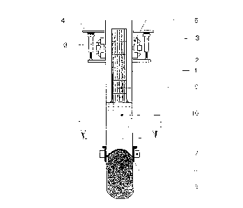
In Figure 1 there is shown a self-baking electrode which is heing coll.~;ume(J in ;~ .~mel~ing
furnace (not shown) situated below the electrode. The electrode comr)li.~;e~ ;ln oulel
30 casing 1 made from a current conducting material. The casing I i.~ rougl1 all elecllode
suspension frame 2 and through hydraulic electrode regulalion cylindel~ ~ ~usr)cll(le(l in
the building construction 4. Conventional electrode holding- and slippillg de~dces ;~ are
arranged for holding of the electrode and for slipping the elecîlode do\~llw;ll(lly ;~ il is
being consumed in the furnace. In the lower part of the elecllode lhele i.~i ~rl;~ e(l ~Onl;~Ct
35 clamps 6 which are pressed against the surface of llle elecllodc h)~ call~i ol .
SUE~:s t I I LITE SHEEr
W096103849 t709lo PCr/N095/00123
eonventional pressure ring 7. The contact clamps 6 are connected to eleclrical condui~s
(not shown) in order to supply eleetric operating eurrent to the electrode. Due Ln the heat
whieh are generated in the earbonaeeous electrode paste, the paste will he hea~ed in ~he
area of eurrent supply and the paste is being baked into a solid electrode g. Th-: electrode
5 paste is supplied to the top of the eleetrode easing 1 in the form of solid cylinders ~) and
the paste will due to the heat soften and fill the eomplete cross-sectioll ol` the elec~rode
easing and forrn a liquid layer 10 of eleetrode paste.
The easing 1 shown in Figure 2 is equipped with a plurality of innel rihs l l made l;om
10 graphite sheets having a ratio between radial length and thickness of 2():1. By using libs
11 made from earbon materials eont~min~tion of the product ploduced in tll~ .smelling
furnaee with iron from steel ribs, is avoided. Also the disadv;mtages ellcoulll~ned hy tlle
known self-baking eleetrode withnut radial inner ribs and where i~ heillg u.~ied C;ll bon
inserts as disclosed in Norwegian patent No. 454()~, are avoided. The calholl rihs have
15 sueh a strength that they are able to earry the weight of ~he hal;ed elccllodc ~nd lullhe
have a good eleetric conductivity causing the electric current ~sul~plicd vi~ c colllac
clamps 6 to be eondueted inwardly into the eleetrode pasle 1() and ~helehy c;nl.~ic a ral id
baking of the eleetrode. Further, eonventional eleetrode holding and slil-r ing d~vices can
be used without modifileations also for the eleetrode according to lhe r)resclll invcnlion.
20 The eleetrode aeeording to the present invention ean thereby be ~ul inlO use in a simr)le
and eost effieient way.
Two embodiments for affixing the radial carbon sheets to the electlode ua.~illC ale sllow
in Figures 3 and 4.
Aecording to the embodiment shown in Figure 3 individual se~lioll.~; ol ~ elecllocle
casing 1 are equipped with an inwardly extending tlange 12. The c~lholl rihs I l are
affixed between flanges 12 on adjacent sections of electrode casing hy me;~ ol holl.~
and nuts 14. In this way the carbon rihs 11 are affixed to the casine in ;l .~ihll~-le w~y. In
30 addition glue ean be applied on the contact surfaces.
According to the embodiment shown in Figure 4 the casing i~ e~uir)r~l willl inwaldly
extending flanges 16 in a number equal to the numher ot carhon rih.~ I I al~ e calho
ribs 11 are glued to the flanges 16 hy means of a suilahle glue. Thc COllll~`CliOll C.lll il
35 necessary be reinforced hy means of holts and nuts.
SUB~ LITE ~HEET
W096/03849 ~ ~9~ PcrlN095/00123--
In Figures 5 and 6 there are shown an embodimen~ of the present invention wh~re th~
electrode has a substantially rectangular cross-section. For such electrodec cc)llvelltion;ll
eleetrode holding- and slipping deviees shown in Figure l eannot he used. In order to
5 hold the eleetrode and to supply eleetrie eurrent to the electrode. the eleetrode casing hc,
in addition to the inner radial carbon ribs 11, equipped with outer radial rih.c 17 made
from an eleetrieal conducting material, such as steel. aluminium or carhon. In o rder to
supply eleetrie operating eurrent to the eleetrode i~ is used eurrenl supply device.c 18
which are intended to elamp against the outer ribs 17 in the way descrihed in Norwegiall
patent No. 147168. In order to hold and to slip the electrode, i~ is used elec~lt)de holding-
and slipping devices as described in Norwegian paten~ No. 147985. Thic CUllCllt .cur)ply
device and the holding- and slipping devices do not impose any radi;ll lorce.c ;ncainsl llle
electrode casing 1 whereby the casing I can be made t;om a lhiml~l malel ial. whit h
further reduees iron cont:lmin:-tion of the product produced in the smeltillg lurn~cc. The
15 eurrent supply device and the holding- and slipping device.s desclihe(l in Norwegi;
patents No. 147168 and 147985 can also he used for elec~rt de.c h;lvillg olllcl- Clt).
sections than a rectangular cross-section.
5UB~ ITE St~lEET