Sélection de la langue

Search

Sommaire du brevet 2171456 

Énoncé de désistement de responsabilité concernant l'information provenant de tiers

Une partie des informations de ce site Web a été fournie par des sources externes. Le gouvernement du Canada n'assume aucune responsabilité concernant la précision, l'actualité ou la fiabilité des informations fournies par les sources externes. Les utilisateurs qui désirent employer cette information devraient consulter directement la source des informations. Le contenu fourni par les sources externes n'est pas assujetti aux exigences sur les langues officielles, la protection des renseignements personnels et l'accessibilité.

Disponibilité de l'Abrégé et des Revendications

L'apparition de différences dans le texte et l'image des Revendications et de l'Abrégé dépend du moment auquel le document est publié. Les textes des Revendications et de l'Abrégé sont affichés :

  • lorsque la demande peut être examinée par le public;
  • lorsque le brevet est émis (délivrance).
(12) Demande de brevet: (11) CA 2171456
(54) Titre français: ARCHITECTURE DE SYSTEME DE COMMUNICATION EVOLUEE
(54) Titre anglais: ADVANCED COMMUNICATION SYSTEM ARCHITECTURE
Statut: Réputée abandonnée et au-delà du délai pour le rétablissement - en attente de la réponse à l’avis de communication rejetée
Données bibliographiques
(51) Classification internationale des brevets (CIB):
  • H04J 3/17 (2006.01)
  • H04L 12/28 (2006.01)
  • H04L 12/403 (2006.01)
  • H04L 12/46 (2006.01)
  • H04L 12/52 (2006.01)
  • H04L 41/00 (2022.01)
  • H04M 11/06 (2006.01)
  • H04Q 11/04 (2006.01)
(72) Inventeurs :
  • WILDER, DAVID EARL (Etats-Unis d'Amérique)
  • BLACKWELL, STEVEN R. (Etats-Unis d'Amérique)
  • POLK, CHARLES E., JR. (Etats-Unis d'Amérique)
  • NELSON, DAVID PAUL (Etats-Unis d'Amérique)
(73) Titulaires :
  • MOTOROLA, INC.
(71) Demandeurs :
(74) Agent: GOWLING WLG (CANADA) LLP
(74) Co-agent:
(45) Délivré:
(86) Date de dépôt PCT: 1995-06-28
(87) Mise à la disponibilité du public: 1996-02-15
Requête d'examen: 1996-03-08
Licence disponible: S.O.
Cédé au domaine public: S.O.
(25) Langue des documents déposés: Anglais

Traité de coopération en matière de brevets (PCT): Oui
(86) Numéro de la demande PCT: PCT/US1995/008112
(87) Numéro de publication internationale PCT: WO 1996004763
(85) Entrée nationale: 1996-03-08

(30) Données de priorité de la demande:
Numéro de la demande Pays / territoire Date
08/285,260 (Etats-Unis d'Amérique) 1994-08-03

Abrégés

Abrégé français

L'invention concerne un système de communication permettant de coupler une pluralité de terminaux de transmission de données (144, 146, 148, 10, 152) à un réseau téléphonique. Ce système comporte un bus d'accès (124) de réseau téléphonique à multiplexage par répartition dans le temps ayant une pluralité de voies temporelles contenant des données, couplé au réseau téléphonique (110). Il comporte également un bus d'accès aux terminaux numériques couplé aux dispositifs de communication (128, 130, 132, 134, 136, 138), chaque dispositif pouvant être configuré pour accéder à n'importe quelle voie temporelle. Un contrôleur (122) assure la configuration de chaque dispositif de communication lui permettant d'accéder à une voie temporelle.


Abrégé anglais


A communication system for coupling a plurality of data terminals (144, 146, 148, 10, 152) to a telephone network has a time division
multiplexed telephone network access bus (124), providing a plurality of time division slots containing data, coupled to the telephone
network (110), and a digital terminal access bus coupled to the plurality of communication devices (128, 130, 132, 134, 136, 138), each
communication device being configurable to access any of the time division slots. A controller (122) configures each communication device
to access a time division slot.

Revendications

Note : Les revendications sont présentées dans la langue officielle dans laquelle elles ont été soumises.


AMENDED CLAIMS
1. A communication system for coupling a plurality of data
terminals to a first telephone network, comprising:
a first time division multiplexed telephone network access bus,
providing a first plurality of time division slots containing data, coupled
to the telephone network and to a plurality of communication devices,
so as to provide access by the communication devices to the time
division slots;
a second time division multiplexed telephone network access bus
coupled to a second telephone network for providing a second plurality
of time division slots containing data and to the plurality of
communication devices, so as to provide access by the communication
devices to the second plurality of time division slots;
a digital terminal access bus coupled to the plurality of communication
devices, each communication device being configurable to access any of
the time division slots; and
a controller coupled to the communication devices for configuring each
communication device to access a time division slot.
2. The system of claim 1 where the digital terminal access bus has a
carrier senson.
3. The system of claim 2 where the digital terminal access bus
allows multiple access.
4. The system of claim 3 where the digital terminal access bus has a
collision detector.
5. The system of claim 1 where the time division slots have
different duration's.

6. The system of claim 1 where the time division slots have the
same duration.
7. The system of claim 1 further comprising a second multiple time
division network access bus coupled to a second telephone network.

8. The system of claim 1 further comprising a backup multiple
time division network access bus.
9. The system of claim 1 further comprising a control bus coupling
the controller to the communication devices.
10. The system of claim 9 where the control bus is a serial bus.

Description

Note : Les descriptions sont présentées dans la langue officielle dans laquelle elles ont été soumises.

W096/~4763 ~71~56 PCT/US95/(~8112
AD~ANCED COMMUNICATION SYSTEM ARC~TECTURE
Field of the Invention
This invention relates to tplpcommtlnir~tion sy~ s;
sperificAlly, it is related to rack mounted commllnir~tion interfaces.
R~rk~round of the Invention
In a central site in~;pll~tiorl~ a large nurnber of remote users
access a central computer ~ty~ or data base. They may use data
rc mmlmication devices (DCDs) operating over a variety of network
services such as PSIN (public switched telephone network), leased line
analog service, leased line digital services such as DDS and fr~ction~l
T1, and switched digital services such as ISDN (integrated services
digital nelwolk)~ Datapath, and switched 56K services.
A large number of connectionc to the telephone nelwolk are
~e4-1iled, as well as a large number of rornmllnir~tion ports on the
host central computer. FIG. 1 shows a prior art commllnir~tion
~ySLt:lll. A LAN (local area network), WAN (wide area network) or
mainframe computer 10 is rcmnecteA to a multi-port I/O
(input/output) concpntrator 12. A rack 14 of analog mo~Pm~ 16 is
ronnerteA to the roncpnt-rator 12. Each analog modem 16 has a separate
ronnertion to the concPnt ator 12. The rack 14 is connPctecl to a 1.544
megabits per seronA (Mbps) T1 rh~nnPl bank 18 (usually provided with
analog voice cards). The T1 rh~nnPl bank 18 is coupled to public
switched telephone network 20 by T1 line 22. Remote moAPm~ 24
coupled the remote user's ~y .Lt:ms 26 to the public switched telephone
network 20 by way of analog lines 28.
Such a ~y~lell~ has a number of problems. Reconfiguration is
AiMclllt because all of the coll.yonents must be cable together
individually. ~~h~nging a T1 time slot ~signmpnt or replacing a failed
modem would require physically moving devices (such as cards) and
cabling. RedllnA~ncy is available, but only at the expense of providing
~A(litional host ports and telephone network ronnPr~ions.

W096/04763 PCTrUS95/08112
~7~456 2
A Sys~ L that reduces the number of telephone network
~onn~rtionc and host sy:~L~ ports while providing simplified
reronfiguration and redl.n~lAnry is thus highly desirable. t
Brief Descliylion of the Drawings
FIG. 1 is a prior art ~ ~n...ll..irAhon ~y~
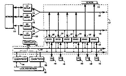
~G. 2 is a block diagram of a rc-mmtmirAtion configured in
accordance with the inv~nti~n-.
Description of the rrerelled Embo~liment
FIG. 2 shows a commllnirAtion system configured in accordance
with the inventiQn Network 110 coupled to a data comm~ni~Ation
~y~ m 112. Data commllnirAhon ~y~ ln 112 is coupled to the network
through a plurality of line interface units 114,116,118,120.
Line interface units (LIUs) 114,116,118, 120 may ~r~"m a
variety of flmrtior~c co~lv~ lg signAl~ from network 110 into data to
be used by the data CommllnirAtion ~y~l~ll 112, and vice versa. For
example, if network 110 were a Tl interface to the public switched
telephone network, then LIUs 114,116,118,120 would ~t lrOllll all of
the required data tr~nsn~i~sion and reception fllnctions for Acc~sing
the twenty-four 64 Kbps (kilobits per second) rhAnnPlc coll~lising the
1.544 Mbps data stream, inrlll~ling signal eqllAli7Ation, timing
recovery, frame AlignmPnt, .signAling reception and trAnClnissic)n~ and
data enco~ing and ~ieco~ling In A~ itinn, the Ws format the data and
provide timing information for the other data roInn~llnirAtion~
devices in the SysL~lll
LIUs 116,120 are bArk--p Ws. In case of a failure of the primary
WS 114, 118, ~en controller 122 would enable the backup Ws 116,
120 to operate in place of the failed LIUs.
Ws 114,116 are coupled to a first time division multiplexed
telephone network access bus 124. As is well known, time division
multiplexing consists of multiplexing access from multiple data
streams into a single higher rate data stream by interleaving data

W0 96/04763 2 t 7 1 4 5 6 PCT/USg5/08112
acccs,dil.g to a preAPfineA Sr~Pnle For example, in a T1 ~y5l~ll, a single
1.544 Mbps data stream is ~ osed of the aggregAtion of twenty-four
64 Kbps data streams (DSOs) plus an 8 Kbps synchror i7Ation pattern.
In T1, frames, which roncict of 8 bits from each of the twenty-four
DSOs plus a single framing bit, are ~ealed at the rate of 8000 per
secor A These a~,gregaLed frames are sent across the network and
demultiplexed at the receiving end into their twenty-four constituent
DSOs.
LIUs 118, 120 are coupled to a seconA time division multiplexed
telephone nel~ork access bus 126. The seconA time division
multiplexed telephone network access bus 126 may be used to access a
telephone network other than telephone network 10.
Alternatively, the se~nf~ time division multiplexed telephone
neL~c,lk access bus 126 may be coupled to the same telephone network
10 as a bArk-lr. Thus, if for some reason if the first time division
multiplexed telephone network access bus 124 failed, then the ~ys
112 could cc)ntin~le operating.
The first and second time division multiplexed telephone
l~eL~ k access busses 124, 126 are coupled to a plurality of
~ nirAtion devices 128, 130, 132, 134. ('ommtlnicAtion devices 128
could be mo~lPmc, digital signal units, ISDN terminal adapters, or even
analog telephone adapters. c oTnmtlnir~tinn devices 128 provide a
mPrh~tli~m for a user to transport data or voice information across the
time division multiplexed network 110.
C'c!mmllnicAtion devices 136, 138 are directly connected to
network 110. Data to commllnirAtion devices 136, 138 is coming
diieclly from the network 110.
All of the devices 128, 130, 132, 134, 136, 138, 114, 116, 118, 120,
154, 156 are coupled to the serial mAnA~ement bus 140. The serial
mAnA~mPnt bus 140 is coupled to controller 122. The serial
mAn~gement bus 140 provides a mechanism whereby the controller
122 can access control, setup and performance information for each
comm..nic~tion device, LIU and concentrator.

W096/04763 2 ~ 7 ~ 45 6 PCT/US95/08112
.
c~QrnmllnirAtion devices 136, 138 are directly ronnPcterl to
nelwo,k 10. Data to romm~lmir~tion devices 136, 138 is rc.ming directly
from the nel~volk 110.
The controller 122 by way of the serial mAnA~m~nt bus 140
5 provides a :,y~ operator the ability to configure, m~nitor and
control each of the comm..nirAti-~nc devices (128, 130, 132, 134, 136, 138)
Ws (114, 116, 118, 120) and conc~ .alols (154, 156). The controller 122
also provides nonvolatile storage for the use of the comm--nir.~tionc
devices, Ws and conc~nt-ators.
~ mml.nic~ti.-n devices 128, 132, 136 are coupled to digital
terminal access bus 142. Digital terminal access bus 142 provides a
multiplexed bus for aggregation of the user data streams from
comnl-lnirAtionc devices 128, 132, 136.
mmllnirAti~n devices 128, 136 are connecte~l directly to digital
terminal 144, 148, re~ecLvely. Controller 122, by way of serial
mAnA~m~nt bus 140, determines whether commllnir~tion devices
128, 136 commlmir~t~ di~ec~ly with digital terminal 144, 148
(respectively) or with the digital tprminAl access bus 142.
~c-mmt-nicAhl-n devices 130, 134, 138 are rortnecte~l solely to
digital tPrmin~l 146, 150, 152. ~'ommtmir~tir~rl device 132 is cor nectell
only with the digital terminal access bus 142.
Digital terminal access bus 142 is coupled to ronc~ntrators 154,
156. C~onc~nt ators 154, 156 (take the aggregated data from the
multiplexed streams present on the digital terminal access bus 142 and
provide access through single ronnectionc to data from multiple data
comml-nirAtion devices. This Plimin~tf~ the necessity for a separate
wired connertion for each data comm~nicAtiQn device. ('onc~ntrators
154, 156 are coupled to a local area network 158. (While a local area
network is shown, any other type of network could be used.)
(~oncent ators 154, 156 are coupled to controller 122.
t'onc~nt-ators 154, 156 could be redllnf1~nt for b~t`kllp purposes, or the
conc~ alors 154, 156 could be connected to separate networks.
A sy~lelll so configured. provides a number of unique
advantages. First, it is si~nifirAntly smaller than existing
impl~m~ntAtinnc, requiring a single rack of equipment instead of

W096/04763 2 1 7 1 456 PCTIUS95/08112
three. As a result, it is also signific~ntly less expensive. SPcon~, it is
much easier to install and m~int~in that other existing
implPmPnt~tionc, Plimin~ting the mass of cAb!ing that is usually
ACSo~ iAte-l with an instAll~tion of this type. Instead, a single LAN
5 cornPction and a single network conT~ection can service an entire rack.
Third, dynamic slot ~ccignmPnt capability creates a unique adv~nhge,
providing a way that hot standby devices can be brought on line to
replace failed devices without physically removing and reinserting
cards. As a result of these and other adv~ntA~Ps, a ~y~lel~ as described
10 herein provides a more complete, capable, flPYihle, and n~Aint~inAhle
tPlecornmuni~ ~tio~c solution than any of the prior art ~y~ s.
We claim:

Dessin représentatif
Une figure unique qui représente un dessin illustrant l'invention.
États administratifs

2024-08-01 : Dans le cadre de la transition vers les Brevets de nouvelle génération (BNG), la base de données sur les brevets canadiens (BDBC) contient désormais un Historique d'événement plus détaillé, qui reproduit le Journal des événements de notre nouvelle solution interne.

Veuillez noter que les événements débutant par « Inactive : » se réfèrent à des événements qui ne sont plus utilisés dans notre nouvelle solution interne.

Pour une meilleure compréhension de l'état de la demande ou brevet qui figure sur cette page, la rubrique Mise en garde , et les descriptions de Brevet , Historique d'événement , Taxes périodiques et Historique des paiements devraient être consultées.

Historique d'événement

Description Date
Inactive : CIB expirée 2022-01-01
Inactive : CIB du SCB 2022-01-01
Inactive : CIB de MCD 2006-03-12
Le délai pour l'annulation est expiré 1998-06-29
Demande non rétablie avant l'échéance 1998-06-29
Réputée abandonnée - omission de répondre à un avis sur les taxes pour le maintien en état 1997-06-30
Exigences pour une requête d'examen - jugée conforme 1996-03-08
Toutes les exigences pour l'examen - jugée conforme 1996-03-08
Demande publiée (accessible au public) 1996-02-15

Historique d'abandonnement

Date d'abandonnement Raison Date de rétablissement
1997-06-30
Titulaires au dossier

Les titulaires actuels et antérieures au dossier sont affichés en ordre alphabétique.

Titulaires actuels au dossier
MOTOROLA, INC.
Titulaires antérieures au dossier
CHARLES E., JR. POLK
DAVID EARL WILDER
DAVID PAUL NELSON
STEVEN R. BLACKWELL
Les propriétaires antérieurs qui ne figurent pas dans la liste des « Propriétaires au dossier » apparaîtront dans d'autres documents au dossier.
Documents

Pour visionner les fichiers sélectionnés, entrer le code reCAPTCHA :


Pour visualiser une image, cliquer sur un lien dans la colonne description du document. Pour télécharger l'image (les images), cliquer l'une ou plusieurs cases à cocher dans la première colonne et ensuite cliquer sur le bouton "Télécharger sélection en format PDF (archive Zip)" ou le bouton "Télécharger sélection (en un fichier PDF fusionné)".

Liste des documents de brevet publiés et non publiés sur la BDBC .

Si vous avez des difficultés à accéder au contenu, veuillez communiquer avec le Centre de services à la clientèle au 1-866-997-1936, ou envoyer un courriel au Centre de service à la clientèle de l'OPIC.


Description du
Document 
Date
(aaaa-mm-jj) 
Nombre de pages   Taille de l'image (Ko) 
Description 1996-02-15 5 227
Abrégé 1996-02-15 1 52
Page couverture 1996-06-18 1 18
Dessins 1996-02-15 2 65
Revendications 1996-02-15 3 58
Dessin représentatif 1997-06-16 1 12
Courtoisie - Lettre d'abandon (taxe de maintien en état) 1997-09-22 1 188
Rapport d'examen préliminaire international 1996-03-08 1 48