Note : Les descriptions sont présentées dans la langue officielle dans laquelle elles ont été soumises.
WO 96/02714 ~ PCT/EP95/02817
REINFORCEMENT STRIP
The invention relates to a grid-shaped reinforcement
strip adapted for reinforcing horizontal masonry joints.
Grid-shaped here means a mesh structure of steel wires of any
cross-sectional shape whatsoever which are welded to one
another.
In masonry construction, consecutive horizontal rows of
building stones are laid on top of one another. After a row
is completed in this process, a layer of binding cement, such
as mortar or adhesive, is spread over its top side. A
reinforcement strip is then laid on top of this layer, and
then a layer of binding cement is again spread over the top
side of this reinforcement strip such that the two layers
then flow into one another through the mesh of the grid,
which results in the creation of one single layer of binding
cement with the reinforcement strip imbedded in it. The
following row of building stones is then laid on top of this,
such that a horizontal joint is created between the previous
and the subsequent row of building stones. This joint is thus
reinforced against the development of vertical cracks which
would tend to run through this joint. If the row of building
stones is longer than the length of one reinforcement strip,
then of course more reinforcement strips are laid end to end
with a certain amount of overlapping to assure the continuity
of the reinforcement. Care is then taken that the breaks in
the reinforcement strips in successive joints be then
situated so as to be staggered in relation to one another.
In order to be adapted for the reinforcement of such
horizontal masonry joints, such strips have a breadth of
approximately 0.6 to 0.9 times the thickness of the wall they
are intended to reinforce, which means a breadth on the order
WO 96!02714 PCT/EP95/02817
2
of between 3 cm and 30 cm, and usually between 5 cm and 18
cm. A practical length for ease of handling on the work site
is in the range between 2 and 7 meters. In general, they are
completely flat, but this does not mean they cannot contain
indentations projecting outside this flat plane, which could
then fit into the cavity of the wall or into vertical
openings in or between the building stones. Further, in order
to be adapted for the reinforcement of horizontal masonry
joints, the mesh structure of the strip needs to be open
enough to permit the mortar, adhesive or other binding cement
sufficiently to flow through the grid when the building
stones are laid, in such a manner that, in the joint between
the two adjacent rows of building stones, a single layer of
binding cement can be formed, that joins the two rows of
building stones with one another and in which the structure
is embedded. And finally, in order to be adapted for the
reinforcement of horizontal masonry joints, a number of the
steel wires which are part of the mesh structure, must each
run straight in the longitudinal direction from the one
1 ongi tudi nal end of the stri p to the other, have a cross-
section ranging between 6 and 20 mmz and a steel tensile
strength of more than 450 N/mm2. These are the reinforcement
wi res . The remai ni ng wi res of the gri d then serve to joi n
together these longitudinally running reinforcement wires
into a single piece in the form of a grid-shaped strip. The
whole of these remaining wires is here called the steel wire
connecting structure. This connecting structure can take on
a great variety of different forms, for example consisting of
a number of separate cross-wires which are welded to the
reinforcement wires on both sides to form a ladder structure
or, by preference, consisting of one single zigzag wire, as
will be given as an example below. Viewed separately, without
the reinforcement wires, this connecting structure can thus
in and of itself form either a number of interconnected
units, or a collection of separate wires. The invention will
WO 96/02714 ~ ~y PCT/EP95/02817
F.
not be limited to any specific embodiment of this connecting
structure, although the embodiment as one single zigzag wire _
will be the preferred embodiment.
A usual embodiment for such a grid-shaped reinforcement
strip is the one in which the strip contains two straight and
continuous steel reinforcement wires with round cross
section, running in parallel in the longitudinal direction of
the strip and at a distance from each other and forming the
side edges of the strip, both thus adjacent reinforcing wires
being connected with one another by means of a steel wire
connecting structure which is spot welded on both sides to
the mutually facing sides of said adjacent reinforcement
wires. This connecting structure consists preferably of one
single continuous steel wire with a round cross-section,
which runs from the one longitudinal end of the strip to the
other in a V-shaped zigzag line running back and forth from
one contact location on the inner side of one of the two
adjacent reinforcement wires to a contact location on the
inner side of the other adjacent reinforcement wire, in which
the wire is spot welded at the successive contact locations
to the respective reinforcement wires. Here, the inner side
of a reinforcement wire is the side which faces the adjacent
reinforcement wire. By preference, the reinforcement wires
are knurled to effect good adhesion with the binding cement.
In such case, the wires in this strip have a diameter in the
range of from 3 to 4 mm. Since the zigzag wire, or more
general l y the steel wi re connecti ng structure, i s spot wel ded
on the inner sides of the reinforcement wires and not on the
upper or under sides, the thickness of the strip is equal to
the diameter of the wires.
In order to make i t poss i bl a to obtai n masonry wi th
thinner joints, a method is known from GB 1 403 181 where
such strips, after welding the wires with round cross-
CA 02171541 2005-02-02
4
section, are rolled into a flattened shape. A reinforcement strip is
thus obtained in which the zigzag wire and the two reinforcement
wires of the strip have been flattened in the plane of the strip to a
thickness which can be less than 1.75 mm and with a thickness-
breadth ratio which can be less than 0.3.
The aim of the invention is to provide a reinforcement strip,
also with a flattened shape but with a structure, which offers a
number of advantages and further, although not limited thereto, is
suitable for being made in very thin form of execution, also of less
than 1.75 mm and with a thickness-breadth ratio which can be less
than 0.3. Here, the number of reinforcement wires in the strip need
not necessarily be limited to two, and thus there can be more than
two reinforcement wires present in the strip. Between each two wires
15 of each distinguishable pair of adjacent reinforcement wires, then,
there is a corresponding part of the steel wire connecting structure,
which is not necessarily limited to a wire running in a V-shaped
zigzag line.
20 In one particular embodiment there is provided grid-shaped
reinforcement strip adapted for reinforcing horizontal masonry joints,
which strip in the longitudinal direction comprises a number of
straight and continuous steel reinforcement wires which are flattened
in the plane of the strip, in which the adjacent reinforcement wires
25 are connected with one another by means of a steel wire connecting
structure which is spot welded on both sides to mutually facing sides
of said adjacent reinforcement wires, characterized in that the spot
welds have an unflattened structure, and that each aforementioned
steel wire connecting structure comprises a number of steel wires
30 having a thickness which is smaller than or equal to the thickness of
said reinforcement wires.
CA 02171541 2005-02-02
4a
In the reinforcement strip according to the invention the
reinforcement wires have also a flattened shape in the plane of the
strip, preferably with a thickness which is less than 1.75 mm and a
5 thickness-breadth ratio which is less than 0.3, and this strip is further
characterized by the fact that the spot welds have an unflattened
structure and that said steel wire connecting structure comprises a
number of steel wires having a thickness which is not greater than
that of said reinforcement wires. By preference, this steel wire
10 connecting structure consists of one single zigzag wire such as
described above.
The above characteristics mean that this is a reinforcement
strip which has not been made thin by means of
WO 96/02714 ' PCTIEP95/02817
~~.'~1~41
~~ ,.
rolling the entire piece flat, but rather by welding together
what on the one hand are thin pre-flattened wires, e.g. pre-
rolled bands, to serve as reinforcement wires, with what, on
the other hand, are th i n wi res sel ected not to be thi cker
5 than the thickness of the bands and which serve as the
connecting structure. This new concept offers a number of
important advantages.
On the one hand, this concept avoids the necessity of
having to roll the welds flat afterwards, which would result
into flat-rolled welds with a flattened structure, i.e. the
cold worked metallographic structure of a weld. In tensile-
strength tests indeed of the known strips, it was observed
that the breakage always occurred at such a weld, and at a
tension of approximately 500 N/mm2. It therefore made no
sense to give the reinforcement wires a greater tensile
strength than that of their weakest spots. Due to the fact
that such wel ds are no 1 onger present, i t becomes possi bl a to
increase the tensile strength of the reinforcement wires to
600 N/mm2 and more, though for manufacturing reasons not
generally higher than 1000 N/mm~. Moreover, the flatter the
earlier strips were rolled, in order to be suitable for
correspondingly thinner joints, the more cold deformation
there was of the welds and thus the weaker these weak spots
became. Due to this fact, the flat-rolling of the strips to
thickness-breadth ratios of the originally round wires of
under 0.3 was not recommended, and flatter embodiments were
not normally available on the market.
On the other hand, since the pre-flattened
reinforcement wires in the invention can preferably be pre-
rolled wires, the possibility is opened up of using rolled
wires - in a preferred embodiment - that have been counter-
rolled, in which then at least the sides to which the spot
welds are to be applied display a flattened, roughly straight
WO 96/02714 ' PCT/EP95/02817
~1~~~416
edge, approximately perpendicular to the plane of the band,
in contrast to the rounded edge of a wire that as part of a
reinforcement strip has been rolled flat between two rollers.
This flattened edge turns out to be very useful in preventing
difficulties in the welding of very thin bands to the equally
thin - or even thinner - wires of the connecting structure,
when these wires have a round cross-sectional shape, as
preferred. The spot welding of the rounded edge of a very
thi n band (under 1. 75 mm) wi th the thi n round wi re of the
connecting structure (also under 1.75 mm) turns out to be
difficult to accomplish with a sufficiently fast welding time
and without the risk of burning through the thin wire because
there is too little contact surface area. Thanks to the
flattened inside edge, the use of thin bands and of wires
under 1.75 mm and the manufacture of thin strips having a
thickness of less than 1.75 mm has become much easier, in any
case under economical manufacturing circumstances.
Compared with the earlier strips, which were rolled
flat as a single piece, there is yet another advantage, which
relates to the wires of the connecting structure. These were
rolled flat to form broad bands such as are shown in the GB
patent referred to above, and due to this fact, the size of
the mesh opening is diminished by a not to be disregarded
percentage, and it is this mesh opening through which the
binding cement makes the attachment from the lowest row of
building stones to the highest row. The size of this opening
becomes especially important when stones are laid with very
thin joints containing very little binding cement,
particularly in the technique where adhesive is used as
binding cement for the attachment of smooth building stones
which have been fabricated in moulds. In the concept .
according to the invention, however, very thin round wires
can now be selected with a final diameter that is not larger
than the thickness of the reinforcement wires and these thin
WO 96/02714 ~ ~'~ I 5 41 PCT/EP95/02817
7 _
round wires are now no longer rolled flat, which would cause
them to broaden.
Finally, there is a further advantage in terms of the
simplicity of fabrication when one wants to roll the strips
till they are very thin. In manufacturing strips that are
rol 1 ed fl at as a si ngl a pi ece, i t i s di ffi cul t to fl atten the
wires in an economical manner, more specifically when a
thickness-breadth ratio of less than 0.3 is aimed at. For
this purpose, it is necessary to start rolling in several
passes with rolling equipment of relatively large dimensions
and relatively large pressure values. The rolling of separate
round wires however into bands of very flat shape, by means
of continuous multiple-pass rolling in line, with the
possibility of counter-rolling in the final pass, for example
with a turks head, is a sufficiently common technique in
already existing and known small ordinary rolling equipment,
and it is a technique that has already attained a high level
of reliable quality. This technique can also be utilized for
flattening the reinforcement wires in the reinforcement
strips of the invention. The same holds for the preferred
round wires of the connecting structure, the manufacture of
which by drawing to small final diameters under economical
conditions being a matter of routine. Moreover, immediately
after rolling and before welding, the flat sides of the
reinforcement wires can be given a knurled surface which
remains unchanged in the reinforcement strip as final
product. In the technique in which the strip as a single
piece is rolled flat, however, the knurled surface which in
some cases is introduced beforehand in the reinforcement
wires is then rolled away. If one nonetheless wishes to
~ introduce the knurling afterwards on the strip itself, then
it is difficult to prevent the strips from curling up during
the knurling process. The straightening of such a strip
afterwards into an acceptably straight piece is sufficiently
WO 96/02714
;" PCT/EP95/02817
8
complicated for giving up the that the idea of knurling the
welded strip. When separate flat wires are knurled however,
and they curl, the technique for straightening them into a
straight shape by alternate bending between relatively small
straightening rollers is a simple, well known technique which
does not affect the knurling. This knurling is advantageous
for a better adhesion of the reinforcement wires to the
binding cement.
Here the invention will now be further explained in
terms of an example and with reference to a number of
figures. These include:
Figure 1 a preferred embodiment of the invention,
in which the strip comprises two
reinforcement wires with a steel wire
connecting structure between them which
cons i sts of one si ngl a steel wi re i n the
form of a U-shaped zigzag line.
Figure 2 shows the embodiment of Figure 1 in cross-
section along the line AA of Figure 1.
Figure 3 shows an analogous cross-section of a
reinforcement strip according to the
aforementioned prior art.
Figure 4 shows schematically a method by which the
embodiment according to Figure 1 can be_
manufactured.
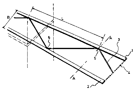
The reinforcement strip as shown in Figure 1 comprises
two reinforcement wires 1 and 2, between which the connecting
wire 3 runs along a U-shaped zigzag line, (i.e. along a sine
curve, the sides of which have been straightened to form a
WO 96/02714 t ~ 17~ 1 ~ 41 PCTIEP95102817
9
series of adjoining 'V's, such as can be seen in the figure).
The breadth B of the strip is 10 cm, and the wavelength L of
the zigzag line is 40 cm.
The reinforcement wires are continuous wires, i.e. non
interrupted, and they run parallel with one another from one
longitudinal end 4 to the other (outside the figure and not
drawn). The cross-section of the reinforcement wires is
rectangular, with the longer dimension in the plane of the
strip, (i.e. in the plane in which the two parallel wires are
located). The breadth b of the reinforcement wires is 8 mm
and the thickness d is 1.5 mm, as can be seen in the cross-
sectional figure of Figure 2. Here, the thickness-breadth
ratio of these reinforcement wires is thus equal to 0.1875.
The reinforcement wires are made of carbon steel with a
carbon content of 0.12 and with a tensile strength of
approximately 600 N/mm2. Although this is not visible in the
drawing, the surface of the flat sides of the reinforcement
wires 1 and 2, (i.e. the sides with aforementioned longer
dimension as their breadth), comprises a number of 3 mm broad
transverse impressions, one per 6 mm of length. These
impressions are the knurls, which serve to improve the
adhesion of the reinforcement wires to the binding cement.
The connecting wire 3 runs along aforementioned V-
shaped zigzag line from one longitudinal end 4 of the strip
to the other. In addition, this connecting wire 3 also runs
transversely back and forth from a contact location 5 on the
i nner si de of rei nforcement wi re 1 to a contact 1 ocati on 6 on
the inner side of reinforcement wire 2, thus creating the
zigzag line. The "inner side" of a reinforcement wire is
therefore the thin side which is turned towards the other
rei nforcement wi re, as i s shown i n Fi gure 2 for the i nner
side 7 of reinforcement wire 2, and for the inner side 7' of
reinforcement wire 1 in contact location 5. In the successive
WO 96/02714 ' ~ ~ ~ . .. PCT/EP95/02817
contact locations 5 and 6 which are thus created here in the
form of contact points, the wire 3 is spot welded to the
reinforcement wire with which it is in contact. This wire 3
is made of relatively soft steel, and can easily be drawn to
5 a round wire of 1.5 mm diameter such that it does not exceed
the thickness of the reinforcement wires. The tensile
strength of the wire is approximately 100 N/mm2.
Figure 3 shows an analogous cross-section of a
10 reinforcement strip according the aforementioned prior art.
This comprises two reinforcement wires 8 and 9 and a zigzag
wire 10, which originally had round cross-sections of 4 mm in
diameter and which were welded together to form a strip in
which the wires 8, 9 and 10 run in the same way as in Figure
1, and in which the strip thus obtained is afterwards rolled
flat as a whole into the shape which can be seen in cross-
section in Figure 3. The weld 18 by means of which the round
wires have been attached to one another is thus a cold rolled
weld with a flattened structure. Furthermore, all the wires,
including both the reinforcement wires and the zigzag wire,
have thus obtained a form which is flattened in the plane of
the strip. The edges (i.e. the short sides of the flattened
wires) have all been rounded outwardly in the process of
being rolled flat. In the invention, however, by preference
at least the inner side of the reinforcement wires has a
flattened edge, in order that the spot weld at the contact
point 5 (Fig. 2) should have sufficient contact surface area.
In the process of flat-rolling the separate wire from
beforehand, this edge is counter-rolled in the last pass so
that the outward rounding created by the flat-rolling in the
previous passes is again flattened. This generally results in
a straight edge on the inner side, perpendicular to the plane
of the strip. By preference, the outer side is also counter-
rolled, so that the reinforcement wires have a rectangular
cross-section.
WO 96/02714 - ~ ~'~ I ~ 41 PCT/EP95/02817
11
Figure 4 is a schematic diagram of a preferred method
of manufacturing the reinforcement strip according to Figure
1. Each of the reinforcement wires 1 and 2 has been
separately rolled beforehand in a continuous process
involving a number of passes in line, and in the final pass
it has also been counter-rolled to form a wire with a
rectangular cross-section, having a thickness of 1.5 mm and
a breadth of 8 mm. A turks head can be used for thi s purpose.
After the final pass, the wire runs through another roller
which presses the knurls in the surface of the wire. The flat
wires thus obtained are on large spools (not in drawing)
which are continuously unrolled, each being fed at the same
speed and in parallel through a straightener (not in the
drawing) in the direction of the arrow 11 to a spot welding
station, which in this figure is represented by the zone Z.
The strai ghteners serve to el imi nate the permanent fl exure i n
the wires (caused by the knurling and winding-up) in order
thus to provide a straight wire to be fed into the spot
welding station and to obtain a straight reinforcement strip
without internal bending stresses (which would cause the
strip to curl). Such straighteners are sufficiently well
known in wire processing technology. They comprise a number
of straightening rollers, set up in such a manner that the
wire which is fed through them is bent alternately in the one
and then in the other direction, which results in the
residual internal stresses in the wire being reduced to zero.
In this application the bendings are applied in the plane
perpendicular to the direction of the breadth of the wire.
The wire 3 for the steel wire connecting structure is
a pre-drawn wire, i.e. already drawn before towards a round
cross-sect i on . The di ameter i s sel ected not to be greater
than the thickness of the reinforcement wires, as for example
1.5 mm. This wire is also continuously rolled off a spool and
fed in the direction of arrow 12 to the spot welding station.
WO 96/02714 '~ ~ PCT/EP95/02817
12
The positioning slat 13 ensures that the wires 1 and 2 are
fed in parallel in a single plane with their flattened
surfaces in this plane, and that wire 3 is also fed into this
same pl ane. The wi res 1 and 2 are fed through the wel di ng
station via guide rollers 14 and 15, respectively, each of
which has a groove around its circumference into which the
outside edge of either wire 1 or wire 2 fits, so as to hold
these wires fast for the spot welding. In the spot welding
station, wire 3 is fed through a guide 16, which also serves
as a welding electrode. This guide is V-shaped in the plane
perpendicular to the direction in which the wires 1 and 2 are
fed. This guide executes a transverse back and forth movement
which is synchronized with the feeding speed of the wires 1
and 2, and this results in the wire 3 being brought into
contact alternately with the inner sides of reinforcement
wires 1 and 2. And together with this back and forth
movement, this guide also executes a rotation within its own
plane and around the point of the V-shape. Thus, when in
position 16' against wire 1, the one leg of the V presses the
wire 3 against the inner side of wire 1, as drawn in the
figure, and when in position 16" against wire 2, the other
1 eg of the V presses the wi re 3 against the i nner si de of
wire 2. At this moment of pressing, then, a welding current
is sent from this guide to the wire 1 or 2, through the
contact point of wire 3 with wire 1 or 2. With this method,
and in combination with the spot welding, the steel wire
connecting structure is fashioned in the form of a V-shaped
zigzag line.
At the outlet of the welding station, then, a
continuous reinforcement strip appears which is cut into
regular 3 meter lengths. These straight 3 meter strips are .
then laid on top of one another to form bundles of such
strips, which are then packaged. For the very thin
reinforcement strips, however, which have been made possible
WO 96/02714 ' - ~. ~ a v
:.. PCT/EP95/02817
13
by the invention, this continuous strip can also remain uncut
and be rolled up into rolls which can then be cut to the
needed length when used on site.