Sélection de la langue

Search

Sommaire du brevet 2171902 

Énoncé de désistement de responsabilité concernant l'information provenant de tiers

Une partie des informations de ce site Web a été fournie par des sources externes. Le gouvernement du Canada n'assume aucune responsabilité concernant la précision, l'actualité ou la fiabilité des informations fournies par les sources externes. Les utilisateurs qui désirent employer cette information devraient consulter directement la source des informations. Le contenu fourni par les sources externes n'est pas assujetti aux exigences sur les langues officielles, la protection des renseignements personnels et l'accessibilité.

Disponibilité de l'Abrégé et des Revendications

L'apparition de différences dans le texte et l'image des Revendications et de l'Abrégé dépend du moment auquel le document est publié. Les textes des Revendications et de l'Abrégé sont affichés :

  • lorsque la demande peut être examinée par le public;
  • lorsque le brevet est émis (délivrance).
(12) Demande de brevet: (11) CA 2171902
(54) Titre français: SYSTEME DE COMMUNICATION INFRAROUGE
(54) Titre anglais: INFRA RED COMMUNICATION SYSTEMS
Statut: Réputée abandonnée et au-delà du délai pour le rétablissement - en attente de la réponse à l’avis de communication rejetée
Données bibliographiques
(51) Classification internationale des brevets (CIB):
  • H04B 10/114 (2013.01)
  • H04R 03/00 (2006.01)
  • H04S 01/00 (2006.01)
(72) Inventeurs :
  • SAMARAI, LAITH FARIS (Royaume-Uni)
(73) Titulaires :
  • CALEDONIAN AIRBORNE SYSTEMS LIMITED
(71) Demandeurs :
  • CALEDONIAN AIRBORNE SYSTEMS LIMITED (Royaume-Uni)
(74) Agent: SMART & BIGGAR LP
(74) Co-agent:
(45) Délivré:
(22) Date de dépôt: 1996-03-15
(41) Mise à la disponibilité du public: 1997-09-16
Licence disponible: S.O.
Cédé au domaine public: S.O.
(25) Langue des documents déposés: Anglais

Traité de coopération en matière de brevets (PCT): Non

(30) Données de priorité de la demande: S.O.

Abrégés

Abrégé français

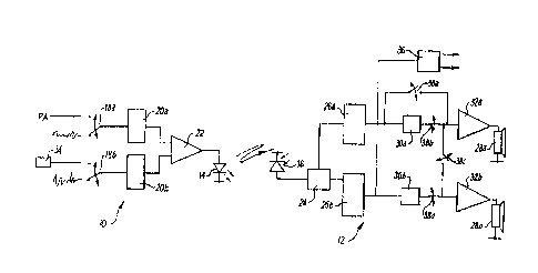
Émetteur (10) et un ou plusieurs récepteurs (12) liés par rayons infrarouges au moyen de DEL (14) et photodiodes (16). Normalement, le système de divertissement de bord est modulé sur des voies gauche et droite pour produire un effet stéréophonique sur les écouteurs d'un utilisateur (28a, 28b). Il émet un signal d'annonce sur un canal et un signal de code sur l'autre. Le récepteur (12) détecte le code (au point 36) afin de mettre en marche un dispositif de commutation (38) qui rend inopérantes les commandes de volume de l'utilisateur (30) et permet ainsi l'audition de l'annonce à plein volume. On présente également des moyens améliorés de réception des signaux infrarouges, qui atténuent les effets d'interférences lumineuses ambiantes.


Abrégé anglais


A transmitter (10) and one or more receivers (12) are
linked by infra red transmission via LED (14) and
photodiode (16). In normal use, in-flight entertainment
is modulated on left and right channels to give stereo
sound on a user's earphones (28a, 28b). Transmitter
public address signal on one channel and a code signal
on the other channel. At the receiver (12), the code is
detected (at 36) to operate receiver switching means
(38) which disable the user's volume controls (30),
thus ensuring that the public address message is heard
at full volume. Also described are improved infrared
signal receiving arrangements mitigating the effects of
ambient light interference.

Revendications

Note : Les revendications sont présentées dans la langue officielle dans laquelle elles ont été soumises.


THE EMBODIMENTS OF THE INVENTION IN WHICH AN EXCLUSIVE
PROPERTY OR PRIVILEGE IS CLAIMED ARE DEFINED AS FOLLOWS.
1. A communication system comprising a master station
including a transmitter, and a plurality of receiving
stations, each receiving station having a respective
individual volume control; and the master station
includes means for overriding the volume controls of
the receiving stations.
2. A system according to claim 1, which uses infra red
transmission between the transmitter and the receiving
stations.
3. A system according to claim 1 or claim 2, which is
a stereo system having two channels and the overriding
means comprises:
means in the master station for transmitting a
code signal on one channel, and
means in each receiving station responsive to
said code signal to disable said one channel and to
bypass the volume control of the other channel.
4. A system according to claim 3, in which the code
signal is a continuous monotone.
5. A receiving apparatus for use in an infra red
communication system, the apparatus being in the form
of a head set having left and right earpieces joined by
a head band, the apparatus including a plurality of
photodetectors positioned on the head set and facing in
different directions.
6. Apparatus according to claim 5, in which there are
four photodetectors positioned one at the front and one
at the rear of each earpiece.

7. Apparatus according to claim 5 or claim 6,
including circuit means operating to reduce the signal
from a given photodetector as the light incident
thereon increases.
8. Apparatus according to claim 7, in which the circuit
means comprises a feed-forward system.
9. Apparatus according to claim 8, in which the feed
forward system, for each photodetector, includes a load
element which provides a load resistance which varies
inversely with the output current of the photodetector.
10. Apparatus according to claim 9, in which the load
element is a bipolar transistor.
11. Apparatus according to claim 10, including a
constant current source connected in parallel with the
photodetector to the transistor emitter.

Description

Note : Les descriptions sont présentées dans la langue officielle dans laquelle elles ont été soumises.


M.qR--9~ 14 13 FROM MURGITROYD Ei~ CO. ID &11413078401 PAGE 3~15
2~71902
1 In~ra Red Co~unication $ys~ems
3 This in~ention rela~es to cordless ~o~m~nication
4 systews using in~ra red light. The invention is
partic~larly, ~ut n~t ex~lusively, useful in ~ublic
6 add~ess and entertain~ent sys~ems for aircr~ft,
7 especi~ he~icopters.
~ It is customary in passenger-car~ying heli~op~e~s to
pro~ide each rA~Anger with ~ h~ad set whic~ ~cts ~s ~n
~1 ear defender. The head se~ re~eives ba~L O~n~ musi~
1~ a~d cr~w safety annou~¢e~nts~ It is known to use an
13 infra ~d cordless ~ystem to com~unicate with ~he
14 individual head se~s.
1~ The known systems have two disadvant~ges:
17
1~ 1 Each p~ Anger has an individ~al volume con~rol
ls switch which may ~e turned low if th~ ba~kgro~nd
music i~ unacceptable. However, a user with ~he
~I vo~ume turned low is likely not to hear safety
2~ announcements~
23
Z4 2 C~r~uni~tion ~an be lost ~ecause of interference

15--M~l~--96 14 13 FROM.MURCITROYD a co . ID 01413078401 PACE 4~15
2171902
1 by direc~ or reflect~ sunlight.
3 In ~ccordance with one aspe~t of the present invention,
4 a com~uni~ation syste~ comprises ~ master station
S including a ~ransmi~ter, and a plurality of receiving
~ stat~ohs~ cac~ receiving s~ation having a respective
7 ir.dividual volume control; and ~he ~aster ~tation
8 includes means for overriding tne volume çontrols of
g the recei~ing stations.
1~
11 Preferably, the syste~ uses infra red ~r~n~ ion
12 ~etween the transmitter and the recei~ing station~.
13
14 Pre~e~ably, the system is a ste~eo syste~ having two
15 ~hAnnels and the overriding means comprises:
16
17 ~eans i~ the ~as~er station for transmitting a cod~
1~ siynal on one ~ n~l r and
19
~0 mean~ in each receivin~ s~ation r~sp~ive ~o said ~ode
21 signal ~o dis~ble said one channel and ~o bypa~s the
22 volu~e ~ontrol of the o~her channel.
23
24 Th~ code signal is suitably ~ con~inuous mono~one.
2 6 ~rom anothe~ ~spe~t, the inventio~ provides ~ ~e~eiving
~7 apparatu~ for use in an infr~ red communication sys~em,
28 the apparatus being in the form of a head ~et hAving
2~ left and ri~h~ earpieces joined by a head ~and, the
apparatu6 incl~ding a plurality of photode~ec~ors
31 positioned o~ the head set and f~eing in different.
3Z dir~ctions~
33
34 Pre~era~ly, the~e are four photode~ec~ors pos~tioned
3~ one ~ the front and one at the rear o~ each e~rpiece.

.15--MAR-9~; 14 13 FROM MURG I TROYD 1~ CO . I D 0141 31il7840 1 PACE 5~15
2171902
1 P~efe~ably, the apparatus in~ludes circuit ~ans
2 operating to reduce the ~ignal f~om a given
3 photode~ector as the light inc;~e~ ~hereon in~reases.
~he c~r~uit maans sui~a~ly ~omprises a feed forw~rd
6 system~ The feed forward system may suitably include,
7 for each pho~o~e~ector, a load ele~ent whi~h provid4s a
loa~ ~esis~ance whiGh YarieS inversely with the ou~put
~ cur~e~nt of t~e photode~ector. Prefer~bly, ~he ~o~d
1~ element is a bip~lar transistor, an~ the system
includes a c~nstant current so~r~e ~onn~ct~d in
1~ para~lel with the p~otodetector to the tr~nsist~r
13 emi~ter.
14
An e~bodiment of thQ inv~ntion ~ill now ~e described,
16 by way of ex~ple, with refe~ence to the drawings, in
17 whi~h~
1~
Fig. l is a ~chematic ~loc~ diag~a~ iLlustra~ing one
~0 form o~ the first aspect of the invention;
Zl
22 Fig~ ~ is a plan view of a headset illu~tratin~ an
23 emho~ n~ of the secon~ aspec~ of the invention;
24
25 Fig. 3 is ~ circuit di~gram illustratin~ a feed forward
2 6 sys~em used 7 n the em~odiment of Fig. 2; and
~7
28 Fiqs. 4a and 4b are graphs illustrating the operation
z 9 of the cir~:uit o~ Fig . 3 .
3~; ~ef~erring to Fig. 1, a public address (PA) and in-
32 ~ h~ ~nter~P i n~t ( IFE~ system ~or use in
33 helicopters us~s infr~red (IR) ~ran-em;-c~;on from a
~ cen~ral unit lO to a plu~ality of h~dscts such as 1~-
The cent~al unit lo includes one o~ more I~ emitting

15--MAR--96 1~ - 14 FROM MURG I TROYD a ~o . I D ! 014 1 3078401 PAGE 6f 1 !ii
217~902
diodes 14, and each headset inc:ludes one o~ ~ore IR
2 photo~i ~des 16,
4 In normal ~se, left a~d right music signall: are
sllpplied f~om a source suc:h as a tap~ deck via
6 SWi1'~h;n~ eans 18a, 18b to lert and right modulators
7 Zoa, 20b. The mod~alated signals are amplifi~d by
~mplifier ~ and applied to the IR e~itting diode 14
9 ~or transmission in ~he aal:~in spa~e.
11 T~ç signal recei~ed at a gi~en h~ac~se~ is de~ected b~r
1~ the! photod~ ode 1~ and receiver cir~uit 24 . ~he lef~ and
13 right c~h~nf~l informatio~ i~ recove~ed by demodula~ors
14 26at 26b and applied to ri~ht dn~l ~ eft earpieces 28a,
~8b ~i~ vol~me controls 30a, 30b ~nd ~plifiers 32a,
1~ 3~ . ~e user ~ay th~s selec~t a desireel ~olume for
17 lis;t~ning to the I~E.
18
19 When a P~ announcem~nt is to be mad~, the switch;n~
2 0 means 18a, 18b is opera~ed to cohnect the right c:hannel
~1 modulator ~Oa to ~ PA so~ur~e ~suçh as a ~isrophone) and
22 t4e lef~ channel modulator 20~ ~o a signal yen~ator 34
23 p~oducing a pure sine wave at a p~edeter~in~1
24 freguency. ~he demodulated sine wa~Je at the output of
the demodulator z6~ in t~e headset is detected by a
26 tone detector 36 which operat~s ~wit~hing ~eans 3~a,
~7 3~b, 38c, 38d to swit~h the volume cont~ols 30a, ~Ob
~8 out of circuit and to conhec~ the de~odula~ed PA signal
2~ from the de~odula~or 26~ to both amplifiers 3~a, 3~b.
3a
3~ Thus w~en a PA announcement is made, use~ con~rol of
3~ lis~n7nq volume i~ overridden and all h~a~t u~ers
33 recei~e the annou~cement at a fixed volu~e~
34
3s Turn~n~ ~o FLg. Z r the headset for use in the syste~

- 15--MAR--9E; 14 ~ 4 FR~M MURG I TROYD a co . I D 014 1 307~401 PACE ~ 15
2171902
1 comprise~ ~ headband 40 supporting ea~ shells ~2a, 42
2 c~ntaining loudspeakers in the norma~ manner~ The
3 head~t i~ prov~ded wlth four recei~ing photodi~de~ ~4,
4 46, 48, SO arranged one forward and one aft on ~ac~ of
the ear s~ells ~2a, 42b 5~ as to provi~e four arcs of
6 visibilit~ of reception 44a, 4~a, 48a, ~Oa. In the
7 arrangement shown, the forward arcs and the aft a~~
8 overlap alon~ the ~en~re line of the user' 8 head. This
9 is suita~le for ~commodating normal hea~ movements in
a cabin provide~ with IR tr~nsmitters on ~he forward
11 and aft b~ heA~. Other arran~ements of visibi1ity
1~ ~rcs may be used for ~her situations.
13
14 In aircraft use, an IR sy~tem is sub~ect to
lS inte~fe~ence by strong sunligh~. The int~rfer ng
l~ ~unlight i8 likely ~o co~e f~om a single dire~tion,
17 typic~lly throug~ a cabin win~w, although Lnterference
18 f~om tWO dire~tions is possibl~ owing to reflection
19 from a refle~ive surface within the cabin. Howeverr
interferenc~ from four direction$ is inhe~e~t~y
21 unlikely~ The head~et of Fig. ~ i5 accordingly pro~ided
22 wLth circui~ means for dea1ing with such interferen~e,
23 as will n~w be described.
Z4
~5 ~ig. 3 illustr~tes an exemplar~ det~ctor circuit u~ed
26 with one of the pho~odio~es 4~, the o~her photodiodes
27 each being pro~i~ed with similar dete~r c~r~uits.
28
29 The photodiode ~4 produces a current whi~h is a
30 fun~tion of the incid~nt light energy and
31 ~onventiona~ly the signal for ~mpli~ tion would be
32 rec~vere~ a6 the voltage acro~ a lo~d resisto~ an the
33 photodiode anode. Howe~er, with su~h an arrangement
34 strong sun1ight interferes with reception in three
mo~s, n~mely:

'15-M~R--~36 14 14 FROM MU~!~ITROYD & CO. ID 01413078401 PAGE 8~15
2171902
_ 6
l (l~ St~ong light induces the current ~enerator to
2 produce large quantities o~ dc current which
3 ex~end the voltage pro~uced by the load bey~n~ the
4 supply voltage range hen~e all information i~
~i 108t.
7 523 ~he li~ht will manifest broadb~nd whi~ noi~e
8 generated at the mo~ se~S i~ive element in the
g circ:ui~ e. before preamplification.
11 ~3) The large dc current being produced ~y the
12 photodlode makes the photodiode less sens~tive to
~3 light de~iations, fur~her ~nterfering wi~h the
14 Lec~ion c~pagilities of ~he syste~
16 Of these, the first two can be mitiga~e~ by us~ng dc
17 acti~e feed back and by reducing reception b~ndwidth,
18 but the thi~d mode cannot be reduced by ~hese means.
19
In Pig. 3, the photodiode 44 i~ ~onne~ted in ~ feed
21 ~orward system which act~ ~o increase the
22 tr~ns~sis~ance ~f the ~y-~tem ns the in~ident ligh~
23 increases~ Specifically, th~ photodiode load in~lu~e~
24 the emit~er-collector patA of ~ipola~ junc~ion
tran~i~tor ~2. As ~he photodiode cu~rent vArie~ ~etween
26 ~ypically lO nA an~ 10 mA, the dyna~ic re~i~tance of ~2
27 emitter will ~ary ~et~een approxLmately ~50 kOhm and
28 ~5 Ohm.
This result is desira~le in it~elf, as it giYes
31 discr~mination agains~ high le~els of noi~e induced by
32 high ligh~ intensi~ies~ H~we~er, ~he v~lue of 2S0 kOhM
33 at low light le~els would ~educe ~he syste~ bandwid~h
34 below 10 kH2 an~ lar~e ~ir~u~t noises w~uld ~lso he
induced .

15--MAR--9E3 14 14 FROM MURCITROYD 8, CO. ID 01413078401 PAGE 9,'15
2171902
1 To meet ~his point, the emLtter of Q2 is ~o~ecte~ in
2 parallel to the p~otod~ode 44 and to a stabiliz~d
3 current so~ce provided by transisto~ Q1. If the
4 current ~upplied by ~1 is set at, say, 6 ~A then the
la~gest ~alue o~ the Q2 emi~ter resi~t~nce is set at
6 approxLmately ~ kOhm, which i~ in accord~nce with th~
7 gener~l requi~e~ents of the system.
g The circuit ~ thu~ ~ar described gives a
trans~esistance ~haracteristic ~ illu~trated in
11 Fig. 4~. Howe~e~, the upper lLmit of t~e ph~todiode
12 current i~ around 10 mA, which would give a
13 ~ransresist~n~e of abaut 2~5 Ohm. It would b~
14 beneficidl ~o reduce the eventual trans~esis~ance ~o
zero, and this is ~hieYed u~ing Q4 and R~.
16
17 At some pres~ribed photodio~e c~rrent, ~he ~oltage
18 generated at R2 will exceed ~be and ~h~s redu~e the
19 output volta~e of QS to zero. Thi~ re~ul~s in a
~odified transresi~tance characteristic as s~own in
21 Fi~. 4b, with the point~ 1 and 2 being readil~ Set by
~2 choice of Rl and R2.
~3
24 The circuit of Fig. 3 has a high degree of ~mmunity ~o
2S fl~tuations in dc supply voltage, very ~ circuit
26 noise ~typicall~ about 80~ nY), a high bandwidth ~ dB
27 lLmit typically 310 kH2) ~ an~ low power con~umptio~
2B (typical~y 1.2 mW)~ These ad~an~ages ~r~ in a~ition to
2g the rejectio~ o~ ~nterference ~rom am~lent sunlight.
Using su~fac~ mount technoloqy, the circuit of Fig. 3
31 ~n be Lmplemen~ed with a low ~omponent count in ~n
32 aroa o~ abou~ 0.5 square ~ n~h~,

Dessin représentatif
Une figure unique qui représente un dessin illustrant l'invention.
États administratifs

2024-08-01 : Dans le cadre de la transition vers les Brevets de nouvelle génération (BNG), la base de données sur les brevets canadiens (BDBC) contient désormais un Historique d'événement plus détaillé, qui reproduit le Journal des événements de notre nouvelle solution interne.

Veuillez noter que les événements débutant par « Inactive : » se réfèrent à des événements qui ne sont plus utilisés dans notre nouvelle solution interne.

Pour une meilleure compréhension de l'état de la demande ou brevet qui figure sur cette page, la rubrique Mise en garde , et les descriptions de Brevet , Historique d'événement , Taxes périodiques et Historique des paiements devraient être consultées.

Historique d'événement

Description Date
Inactive : CIB désactivée 2013-11-12
Inactive : CIB en 1re position 2013-02-19
Inactive : CIB attribuée 2013-02-19
Inactive : CIB expirée 2013-01-01
Inactive : Morte - RE jamais faite 2004-03-15
Demande non rétablie avant l'échéance 2004-03-15
Réputée abandonnée - omission de répondre à un avis sur les taxes pour le maintien en état 2004-03-15
Inactive : Abandon.-RE+surtaxe impayées-Corr envoyée 2003-03-17
Lettre envoyée 2001-03-23
Exigences de rétablissement - réputé conforme pour tous les motifs d'abandon 2001-03-13
Lettre envoyée 2001-03-06
Inactive : Lettre officielle 2001-03-05
Inactive : Page couverture publiée 2000-12-21
Réputée abandonnée - omission de répondre à un avis sur les taxes pour le maintien en état 2000-03-15
Demande publiée (accessible au public) 1997-09-16

Historique d'abandonnement

Date d'abandonnement Raison Date de rétablissement
2004-03-15
2000-03-15

Taxes périodiques

Le dernier paiement a été reçu le 2003-03-11

Avis : Si le paiement en totalité n'a pas été reçu au plus tard à la date indiquée, une taxe supplémentaire peut être imposée, soit une des taxes suivantes :

  • taxe de rétablissement ;
  • taxe pour paiement en souffrance ; ou
  • taxe additionnelle pour le renversement d'une péremption réputée.

Les taxes sur les brevets sont ajustées au 1er janvier de chaque année. Les montants ci-dessus sont les montants actuels s'ils sont reçus au plus tard le 31 décembre de l'année en cours.
Veuillez vous référer à la page web des taxes sur les brevets de l'OPIC pour voir tous les montants actuels des taxes.

Historique des taxes

Type de taxes Anniversaire Échéance Date payée
TM (demande, 2e anniv.) - générale 02 1998-03-16 1998-03-11
TM (demande, 3e anniv.) - générale 03 1999-03-15 1999-03-02
TM (demande, 6e anniv.) - générale 06 2002-03-15 2001-02-19
Rétablissement 2001-03-13
TM (demande, 4e anniv.) - générale 04 2000-03-15 2001-03-13
TM (demande, 5e anniv.) - générale 05 2001-03-15 2001-03-13
TM (demande, 7e anniv.) - générale 07 2003-03-17 2003-03-11
Titulaires au dossier

Les titulaires actuels et antérieures au dossier sont affichés en ordre alphabétique.

Titulaires actuels au dossier
CALEDONIAN AIRBORNE SYSTEMS LIMITED
Titulaires antérieures au dossier
LAITH FARIS SAMARAI
Les propriétaires antérieurs qui ne figurent pas dans la liste des « Propriétaires au dossier » apparaîtront dans d'autres documents au dossier.
Documents

Pour visionner les fichiers sélectionnés, entrer le code reCAPTCHA :


Pour visualiser une image, cliquer sur un lien dans la colonne description du document. Pour télécharger l'image (les images), cliquer l'une ou plusieurs cases à cocher dans la première colonne et ensuite cliquer sur le bouton "Télécharger sélection en format PDF (archive Zip)" ou le bouton "Télécharger sélection (en un fichier PDF fusionné)".

Liste des documents de brevet publiés et non publiés sur la BDBC .

Si vous avez des difficultés à accéder au contenu, veuillez communiquer avec le Centre de services à la clientèle au 1-866-997-1936, ou envoyer un courriel au Centre de service à la clientèle de l'OPIC.


Description du
Document 
Date
(aaaa-mm-jj) 
Nombre de pages   Taille de l'image (Ko) 
Dessin représentatif 1997-10-20 1 7
Dessin représentatif 2000-12-10 1 7
Abrégé 1996-06-19 1 24
Description 1996-06-19 7 267
Revendications 1996-06-19 2 58
Dessins 1996-06-19 3 44
Rappel de taxe de maintien due 1997-11-17 1 111
Courtoisie - Lettre d'abandon (taxe de maintien en état) 2001-03-04 1 182
Avis de retablissement 2001-03-22 1 169
Rappel - requête d'examen 2002-11-17 1 115
Courtoisie - Lettre d'abandon (requête d'examen) 2003-05-25 1 167
Courtoisie - Lettre d'abandon (taxe de maintien en état) 2004-05-09 1 175
Correspondance 2001-03-04 2 35
Correspondance 2001-03-05 1 20
Correspondance 2001-03-12 1 22
Taxes 2001-03-12 1 48
Taxes 2002-03-13 1 40
Correspondance reliée au PCT 1996-08-12 1 54
Correspondance de la poursuite 1996-08-26 1 44
Courtoisie - Lettre du bureau 1996-04-09 1 16