Note : Les descriptions sont présentées dans la langue officielle dans laquelle elles ont été soumises.
Wo 96/02368 1 2 1~ 2 ~ 5 4 PCT/ll~g5l~crs1
Shaving a~aldllls.
The invention relates to a shaving apparatus having a housing, provided
with a holder in which at least one cutting unit is mounted, which cutting unit comprises an
PYtern~l cutting m-omhPr and an int~rn~l cutting mPnnher which is rotatably drivable relative
to said Pxt~rn~l cutting mPn her, and provided with a skin ~up~lLillg rim ~ulluu~lding the
5 eY~tern~l cutting member, which external cutting member has at least one hair-entry a~lLu,e
and is mounted so as to be movable relative to the holder, said intern~l cutting member being
in resilient engagement with the eYtprn~l cutting member.
Such a shaving apparatus is known from US-A~,168,570. In the known
ap~dlus the skin su~olLing rim is formed by the edge of the opening of the holder in
which the cutting units are mounted. The skin su~,Ling rim serves for slightly t~ntPning the
skin before the eYtern~l cutting member is moved over the skin. Thus, it is achieved that the
hairs to be severed are better erected so that they can be sc~e.c~ better and closer to the
15 skin. An even more illlpolkult function of the skin suppolling rim is to s.lp~ll the skin
around the eYtPrn~l cutting --c---be~. This ensures that the pl~ Ul~, on the external cutting
member does not become too high. An excessive pl`e~;~ufe leads to skin injury and irritation
because the skin then ~ ,~ t~ s further into the hair-entry a~tules and can come into
contact with the intern~l cutting member. The external cutting member is mounted in the
20 holder so as to allow movement in, preferably, any direction. As a result, the shaving
surface, which is formed by the outer surface of the external cutting lllelllb~. facing the skin,
can readily adapt itself to the shape of the facial area to be shaved. The maximum
pPnni.~ihle tilting angle of the external cutting member, is determined by the length over
which the external cutting member projects above the skin ~u~ Ling rim. A large projection
25 length gives rise to large p~ peaks on the ~,i~heldl parts of the external cutting
I-e.llbel because the skin su~lling Am cannot ~lo~;lly ~u~-l the skin. As already stated
above, a higher ~l~,SSule leads to skin injury and irrit~tion When the external cutting
e.llbel is tilted relative to its ~ci~t~d skin su~ ing Am this Am cannot pclrO~I its skin
~up~llillg function in an optimum Illanner because this skin s.l~l)olling Am is ~ t~
WO96/02368 ., ~ 2 PCT/IB95/005S4
further from the shaving surface of the external cutting member. Moreover, large lln~ecir~hle
pressure peaks are produced on that part of the external cutting member which has the largest
projection length.
It is the object of the invention to provide a shaving a~a,~Lus in which
the ples~ulc; on the external cutting member is controlled more effectively.
To this end the invention is ~lara-terised in that the skin supl)G,Ling rim is
pivotable both relative to its ~ t~d external cutting member and relative to the holder.
This precludes ylc;s~ule peaks on the external cutting member. The eYte~n~l cutting member
can tilt through a larger angle than in the prior-art shaving apparah~ As a result, the
10 shaving app~d~us is better conformable to the shape of the face. Since the external cutting
member is arranged to be movable in any direction and is consequently also depressible,
whereas the a~oci~t~ skin suppci-ling rim is only pivotable and not depressible, a limitation
of the maximum pr~ul~, is obtained. Thus, the skin su~o-Ling rim also has a proleclive
function.
A first variant is ch~rart~n~ in that the skin ~uppolling rim is pivotable
about two axes which are perpendicular to one another.
A second variant is c~r~terised in that it comprises two circular cutting
units whose skin ~u~.ling rims are pivotable about a common axis which extends parallel
to a conn~ting line through the centres of the cutting units.
A third variant is char~ten~ in that it comprises two or more circular
cutting units each having a skin ~upl)olLing rim which is pivotable about an axis situated in a
plane parallel to a shaving plane defined by outer surfaces of the external cutting members,
which axis ecten~s perpen(i~ y to a c~l-necl;-~g line between the centre of each cutting
unit and the centre of gravity of the combination of cutting units.
A morlific~tion thereof is chara~ten~d in that the sldn supporting rims are
coupled to one another by means of a hinge construction. The hinge construction should have
some freedom of movement in the direction of the centres of the cutting ~l~e.~bel~.
Preferably, the hinge construction is a so-called tongue-and-groove construction or an elastic
hinge.
The invention will now be described in more detail with reference to an
exemplary embodiment shown in the drawings. In the drawings:
- ~7~5~
W096/02368 pcTlIBs~loos54
Fig. 1 is a ~~ e view showing a shaving a~dlus with three
cutting units, in which the invention is used,
Figs. 2a-2b show a cutting unit with a skin ~up~lLillg rim which, in
acco~ance with the prior art, is immobile relative to the holder,
S Fig. 3 shows a cutting unit with a skin ~u~lling rim as shown in Fig. 2a
but with a larger tilting angle of the extern~l cutting mPmher,
Figs. 4a-4b show a cutting unit with a skin su~pol~ g rim which, in
accoldance with the invention, is pivotable relative to the holder,
Fig. S shows a cutting unit with an immobile skin ~u~olling rim and the
10 prw~ule distribution near peripheral parts of the cutting member during contact with the skin
in accoldance with the prior art,
Fig. 6 shows a cutting unit with a pivotable skin sup~l~ g rim and the
ur~ distribution near peliphe~dl parts of the cutting member during contact with the skin
in accol.lance with the invention,
Figs. 7a, b, c, d show a cutting unit with a skin su~ g rim which is
pivotable in any direction relative to the holder,
Figs. 8a, b, c, d show a cutting unit with a skin sup~ lg rim which is
pivotable relative to the holder about two muh~ y perpPn~ic~ r axes,
Figs. 9a, b, c show a cutting unit with a skin ~u~polling rim which is
pivotable relative to the holder about one axis,
Figs. 1~13 show dirreç~.~t configur~tions of slla~ing heads with two,
three and four cutting units, l~ s~ ely,
Fig. 14 shows a tongue-and-groove type hinge COnsllu~:liOII between two
skin ~u~ g rims,
Fig. lS is a perspective view of a skin ~u~lling rim as shown in Fig.
14, and
Fig. 16 is a perspective view showing an e1emPnt comrri.cing three skin
SUp~lLing rims for a triple-head shaving appaldlus, the skin :iU~)pOlLil-g rims being coupled
to one another by an elastic integral hinge.
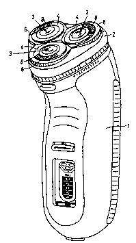
The rotary shaving a~dlus shown in Fig. 1 has a hoi-cing 1 with a
~et~rh~hle holder 2. In the holder three cutting units 3 are mounted, which units each
C"-1J' ;~f an e~tern~l cutting "~f .,.~r 4 and an intern~l cutting ll.e.nber 5 (see Fig. 7a), the
21720~
W096/02368 PcT/Is9s/00554
external cutting member being sullo.li ded by a skin ~Up~lling rim 6. The eYtern~l cutting
mf mber 4, which is generally circular, has a subsl~ lly nat shaving surface 7 and has a
m. llltih-~e of slit-shaped hair entry apellu~Gs 8. The internal cutting member S has a number
of cutters 9 (see Fig. 7a) secured to a support 10. The support can be coupled to a coupling
5 pin 11, which is rotatable by a motor, not shown. The coupling pin 11 is provided with a
spring 12, which urges the int~rn~l cutting member 5 towards the external cutting member 4
so as to m~int~in proper contact bel~æn the cutting m~mhers during shaving. In addition,
the eY~t~rn~l cutting member 4 can be ~u~lled relative to the holder 2 by resilient means, as
described in US-A-4, 168,570. This makes the exte-rn~l cutting member 4 resilient in a
10 direction perpendicular to the shaving surface 7 in such a l"anne. that the external cutting
n-enlbel can also be tilted slightly relative to the holder. Thus, the external cutting member is
movable in any direction relative to the holder. In the prior-art shavers of the type described
above the skin sup~,lii g rim 6 is a rim which is fixedly conn~t~d to the holder 2. In Figs.
2a-2b, which illustl~te the prior-art situation, the skin supporting rims 6 and the holder 2
15 form an integral part. In Figs. 4a-4b, which illustrate the ~ih~tinn in acco,dailce with the
invention, each skin su~pc,lLing rim 6 takes the form of a s~ te part, which is pivotable
relative to both its associated external cutting member 4 and the holder 2.
The eYt~ l cutting member 4 is arranged to be movable in any direction
relative to the holder 2, so that the shaving surface 7 can readily adapt itself to the shape of
20 the facial area to be shaved. This is the prior-art situation shown in Figs. 2a-2b. The line 13
ep,~n~ a curved portion of a facial area to be shaved. As a result of the curvature of the
face the external cutting ~ .-,b~l~ 4 will be tilted through an angle ~1, so that the shaving
surface is in better contact with the curved portions of the face. As is shown in Fig. 2a, the
facial areas which are ~ t~d nearer the ends of the curved line 13 are not in contact with
25 the shaving surface 7. A possibility of achieving this contact would be by allowing a larger
tilting angle of the external cutting member 4 (tilting angle ~Y2). This is illustrat~ in Fig. 3.
It is clearly shown that the curved line 13 is now better in contact with the shaving surface.
However, the ~ t~nce d bGlwGGl the outer portions of the curved line and the skin
sul)polling rim 6 has increased to such an extent that the skin is no longer su~polled by the
30 skin su~llil g rim. See also Pig. 5. At the pelipheldl parts 14 of the cutting member 4 this
leads to large ~l~s~ure peaks (P1) on the skin and a risk of skin injury and irritation.
Figs. 4a-4b i~ t~te the ~itu~tion in accor~ance with the invention. When
the external cutting member 4 is tilted the associated skin ~ pGlling rims 6 are also tilted.
This does not only result in a large tilting angle a2 of the cutting member but it also ensures
wos6lo2368 pcTnBss/oo554
~1 72~5~
that an effective ~uppoll of the skin by the skin su~.ling rim is m~inpinecl, The plc~
(P2) on the ~;Aphclal parts of the cutting member is subst~nti~lly lower. See also Fig. 6.
This provides a better control of the plC~ur~, on the eYtern~l cutting me~nber.
Figs. 7a-7d show a cutting unit in which the skin ~up~lLing rim 6 with
5 the cutting members is pivotable in any direction in the holder 2. For this pul~ose the inner
edge 15 of the opening 16 in the holder 2 holding the cutting unit has a concave shape and
an outer edge 17 of the skin suppGlling rim 6 has a corlG~onding convex shape. The tilting
point bears the reference K. Figs. 7a-7b show the cutting unit in a non-tilted centre positio~
Fig. 7c shows the cutting unit (with the skin s~lLing rim) tilted in one direction and in
10 Pig. 7d tilted in a direction perpendicular thereto.
Figs. 8a-8d show a cutting unit in which the skin sup~lLing rim with the
cutting members is pivotable about two axes perpendicular to one another. For this l~ul~ose
the skin ~up~r~ing rim 6 has bearing projections 18. Por each projection the skin ~L~p~~ g
rim has an arcuate pin 19 which engages an arcuate opening 20 in the projection. Thus, the
15 cutting unit can be tilted about an axis A1. Fig. 8d shows this tilt relative to Fig. 8b. The tilt
about an axis A2, which is perpendicular to the axis A1, is obt~ined in that the projection 18
is slidable in a cylin~lri~l recess 21 in the inner edge 15 of the holder 2. Fig. 8c shows this
tilt relative to Fig. 8a.
Figs. 9a-9c show a cutting unit in which the skin ~ ing rim 6 is
20 pivotable aboue one axis A. For this pul~ose the skin ~ ~fling rim has two ~ metr~lly
opposed projections 22, which engage in o~>cnings 23 in the holder 2. By providing the
~n,j~ction with flat portions 24 and suitably .~ ;oning the openin~s 23 the tilting range
can be limi~d. Fig. 9c shows the tilt relative to Fig. 9b. These projections 22 are also shown
in Figs. 15 and 16. It is obvious that the tilting range can also be limited in another manner.
Figs. 1~13 show dir~cnt configurations of shaving heads with two,
three or four cutting units. Each skin suppolLii-g Am with its associaled cufflng menlbers is
pivotable about an axis IhloLgh the centre of the cutting unit. The tilting axes are disposcd in
a plane parallel to t,he shaving surface 7 (see also Fig. 14). In Fig. 10 the tilting axes are
parallel to the conn~ting line 25 through the centres M of the cutting units and are also in
line with one another. In Figs. 11-13 the tilting axes extend perpendicularly to a connecting
line between the centre of each cutting unit and the centre Z of the combination of cutting
units.
The skin ~u~pulLing Ams of each shaving head can be pivotable
in~ependently of one another. However, they can also be coupled to one another by means of
W096/02368 ,~ 7,~ PCTIIB95/005S4
a hinge construction. Fig. 14 shows a construction in which the skin supporting rims are
coupled by means of a so-called tongue-and-groove coupling. The skin ~uppolling rims
adjoin one another pairwise along portions which define a str~ight line 27 (see ~;ig. 12). Of
these straight portions of each skin ~upl~olling rim one portion has a tongue 28 and the other
5 portion has a groove 29. Fig. lS is a ~lspecLi.~e view showing such a sldn supporting rim.
Finally, Fig. 16 shows a construction for a triple-head shaving app~ , where the three
skin suppolLing rims are coupled to one another by means of an elastic integral hinge 30.