Sélection de la langue

Search

Sommaire du brevet 2172337 

Énoncé de désistement de responsabilité concernant l'information provenant de tiers

Une partie des informations de ce site Web a été fournie par des sources externes. Le gouvernement du Canada n'assume aucune responsabilité concernant la précision, l'actualité ou la fiabilité des informations fournies par les sources externes. Les utilisateurs qui désirent employer cette information devraient consulter directement la source des informations. Le contenu fourni par les sources externes n'est pas assujetti aux exigences sur les langues officielles, la protection des renseignements personnels et l'accessibilité.

Disponibilité de l'Abrégé et des Revendications

L'apparition de différences dans le texte et l'image des Revendications et de l'Abrégé dépend du moment auquel le document est publié. Les textes des Revendications et de l'Abrégé sont affichés :

  • lorsque la demande peut être examinée par le public;
  • lorsque le brevet est émis (délivrance).
(12) Brevet: (11) CA 2172337
(54) Titre français: PIECE RAPPORTEE POUR CLOISON SECHE
(54) Titre anglais: DRYWALL PATCH
Statut: Périmé et au-delà du délai pour l’annulation
Données bibliographiques
Abrégés

Abrégé français

Cette invention concerne une pièce de réparation de cloison sèche qui a essentiellement la forme d'un solide plat. Cette pièce comporte une bande périphérique qui, insérée dans le trou à réparer, empêche la pièce de bouger latéralement durant l'application de l'enduit de rebouchage.


Abrégé anglais


A drywall patch includes a substantially planar body
having a peripheral edge. A depending skirt is spaced from the
peripheral edge of the body. The depending skirt is extended
into an opening in drywall to prevent lateral movement of the
drywall patch during application.

Revendications

Note : Les revendications sont présentées dans la langue officielle dans laquelle elles ont été soumises.


7
THE EMBODIMENTS OF THE INVENTION IN WHICH AN EXCLUSIVE PROPERTY
OR PRIVILEGE IS CLAIMED ARE DEFINED AS FOLLOWS:
1. A drywall patch, comprising:
a substantially planar body having a peripheral edge; and
a depending skirt spaced from the peripheral edge of the
body, the depending skirt being integrally formed as an
uninterrupted peripheral sidewall of one of a molded polymer
plastic pan and wire mesh basket, a bottom of the one of a
molded polymer plastic pan and a wire mesh basket being secured
to the body by adhesive, thereby maintaining the depending
skirt in position to prevent lateral movement of the drywall
patch.
2. The drywall patch as defined in Claim 1, wherein the planar
body is rectangular.
3. The drywall patch as defined in Claim 1, wherein the
depending skirt defines a rectangular cavity.
4. The drywall patch as defined in Claim 1, wherein the planar
body is constructed of a fibreglass mesh material.
5. The drywall patch as defined in Claim 4, wherein the planar
body is covered by at least one layer of drywall paper.

8
6. A drywall patch, comprising:
a rectangular planar fibreglass mesh body having a
peripheral edge;
at least one layer of drywall paper covering the mesh
body; and
a depending skirt spaced from the peripheral edge of the
body, the depending skirt being integrally formed as an
uninterrupted peripheral sidewall of a wire mesh basket, a
bottom of the wire mesh basket secured by adhesive to the body,
thereby maintaining the depending skirt in position to prevent
lateral movement of the drywall patch.

9
7. The drywall patch as defined in Claim 6, wherein the
depending skirt defines a rectangular cavity and a drywall plug
is positioned in the rectangular cavity.

10
8. A drywall patch, comprising:
a rectangular planar fibreglass mesh body having a
peripheral edge;
at least one layer of drywall paper partially covering the
mesh body; and
a depending skirt spaced from the peripheral edge of the
body, the depending skirt being integrally formed as an
uninterrupted peripheral sidewall of a polymer plastic pan, a
bottom of the polymer plastic pan being secured by adhesive to
the body, thereby maintaining the depending skirt in position
to prevent lateral movement of the drywall patch.
9. The drywall patch as defined in Claim 8, wherein the
depending skirt defines a rectangular cavity and a drywall plug
is fixedly positioned in the rectangular cavity.

Description

Note : Les descriptions sont présentées dans la langue officielle dans laquelle elles ont été soumises.

2~723~7
-
TITLE OF THE INVENTION:
drywall patch
NAME OF INVENTOR:
Ira Amy
FIELD OF THE INVENTION
The present invention relates to a drywall patch for
patching holes made in drywall.
P~ .ROUND OF THE INVENTION
During the course of constructing a building out of
drywall, openings through the drywall intended to accommodate
electrical receptacles and the like are sometimes incorrectly
positioned. When this occurs the unwanted opening through the
drywall must be patched. There are, of course, an infinite
variety ways that a person can find himself or herself with an
unwanted hole or opening through the drywall that must be
patched.
Although a number of patents disclose methods or apparatus
for patching drywall, none of the solutions disclosed has
achieved commercial acceptance. United States Patent 3,999,347
which issued to Devlin in 1976 entitled "Handy Helper",
discloses a clamp like tool. This tool has a bow member and
a centrally positioned adjustable stem member. The stem member
is attached to a piece of scrap board. The scrap board is
inserted through an opening in the drywall that is to be
patched. The scrap board is held up against the inside of the
drywall by tightening the stem of the tool. A patching

~172337
compound is then applied to the opening, using the scrap board
for rear support. When the patching is completed, the stem is
withdrawn and the scrap board is left in the wall. The scrap
board serves as temporary backing while during the patching
process. United States Patent 4,358,495 which issued to Parker
in 1982 is entitled "Drywall Patch Kit". The kit includes
qAn~rA~er, a putty knife, a tube of joint filler compound, and
a plurality of patches of varying sizes. Each patch consists
of two circular-shaped layers of drywall paper cemented
together. The patch is made pliable by dipping in water prior
to application. The patch is slightly larger than the opening
being patched. This provides a single thickness of material
around the outer edge of the opening for blending in with the
wall and a double thickness over the opening for enhAnced
reinforcement. United States Patent 4,620,407 which issued to
Schmid in 1986 is entitled "Method for Drywall Patching". The
method disclosed involves the use of a rectangular shaped
repair plug having a front wall, a rear wall and edges which
slope inwardly from the front wall to the rear wall. A
rectangular shaped opening is made through the drywall with
corresponding sloped walls. The mating of the sloped walls of
the repair plug and sloped walls of the opening serve as
backing for the repair plug.
Each of the patents described above provides certain
advantages and has certain inherent disadvantages. With the
drywall patch disclosed by Parker, care must be taken to ensure
that the patch does not slide laterally out of position during
application. Once the patch has dried and set into position,
problems can be experienced due to the fact the patch has no
permanent backing. An object striking the patched area would
likely punch a hole through the two thin ply patch material.
The teaching of Devlin requires the use of a joint filler
compound without backing. As with the Parker patch, the Devlin
patch would be susceptible to damage is accidentally struck.
A further problem may be experienced even in the absence of
striking if the joint filler compound experiences shrinkage.

2112337
-
The most practical of the teachings is that of Schmid. The
patch taught by Schmid i8 installed in such a manner that it
has solid backing. It takes preparation in order to ensure
that both the opening and the patch have sloped edges. It is
difficult, if not impossible, to get the sloped edges exactly
perfect, 80 that the di~tance that the patch extends into the
opening will vary. When the patch extends into the opening
deeper than is desirable, filling will be required. The patch
should be durable enough to withstand blows experienced through
normal use.
SU~IARY OF THE INVENTION
What is required is an improved form of drywall patch.
According to the present invention there is provided a
drywall patch which includes a substantially planar body having
a peripheral edge. A depending skirt is spaced from the
peripheral edge of the body.
The drywall patch, as described above, is simple to work
with and is prevented from moving laterally by the depending
skirt.
Although beneficial results may be obtained through the
use of the drywall patch, as described above, some simple
measures can be made to strengthen the drywall patch thereby
improving its performance. The strength of the drywall patch
is increased substantially when the planar body is constructed
of a mesh material, preferably fibreglass. The strength of the
drywall patch can be even further increased when the depending
skirt defines a rectangular cavity in which is positioned a
drywall plug which provides backing and reinforcement for the
fibreglass mesh body.
BRIEF D~TPTION OF THE DRAWINGS

2~723~7
_,
These and other features of the invention will become more
apparent from the following description in which reference is
made to the appended drawings, wherein:
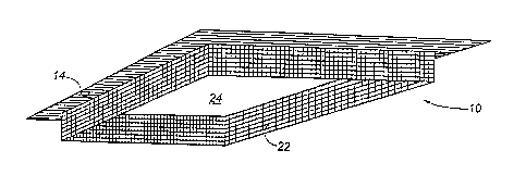
FIGURE 1 is a bottom perspective view of a first
embodiment of a drywall patch constructed in accordance with
the teachings of the present invention.
FIGURE 2 is a top plan view of the drywall patch
illustrated in FIGURE 1.
FIGVRE 3 is a side elevation view, in section, of a second
embodiment of drywall patch constructed in accordance with the
teachings of the present invention.
FIGURE 4 is front elevation view of a wall having an
opening requiring a drywall patch.
FIGURE 5 is front elevation view of the wall illustrated
in FIGURE 4 with the drywall patch illustrated in FIGURE 3
inserted into the opening.
FIGURE 6 is an exploded side elevation view, in section,
of the drywall patch illustrated in FIGURE 3.
nR~T~.Rn nR~TpTIoN OF THE 1~r~KK~ EMBODI~ENT
The preferred embodiment, a drywall patch generally
identified by reference numeral 10, will now be described with
reference to FIGURES 1 through 6.
Referring to FIGURE 2, drywall patch 10 includes a
rectangular, preferably square, planar body 12 having a
peripheral edge 14. Planar body 12 is constructed out of a
fibreglass mesh material across which extends a layer of
drywall paper 20. Referring to FIGURE 1, a rectangular
depending skirt 22 is spaced from peripheral edge 14 of
fibreglass mesh body 12. Depending skirt 22 defines a
rectangular cavity 24. Referring to FIGURES 3 and 6, there is
illustrated a best mode of drywall patch 10. For ease of
assembly, depending skirt 22 is integrally formed at part of

'~7~337
-
a shallow pan or basket 23. Pan or basket 23 can be made of
moulded polymer plastic or wire. The advantage this
construction provides is that planar fibreglass mesh body 12
can be secured by adhesive to a bottom surface 25 of pan or
basket 23. In applications where strength is of importance,
a drywall plug 26 is fixed within rectangular cavity 24 to
provide additional reinforcement, beyond that provided by pan
or basket 23.
The operation of use of drywall patch 10 will now be
described with reference to FIGURES 1 through 6. Referring to
FI~URE 4, there i8 illustrated a wall 28 constructed of drywall
and having an hole 30 requiring patching. A rectangular
opening 32 is cut in wall 28 of a size corre~ponding to the
dimensions of rectangular skirt 22 of drywall patch 10.
Rectangular opening 32 encompasses within it hole 30.
Referring to FIGURE 3, rectangular skirt 22 of drywall patch
10 is then inserted into opening 32 with fibreglass mesh body
12 overlying wall 28. Referring to FIGURE 5, joint filler is
then placed over fibreglass mesh body 12 to cement drywall
patch 10 in position. Referring to FIGURE 3, once the patch
job is completed, drywall patch 10 cannot be pushed through
opening 32 due to the adherence of fibreglass mesh body 12 to
wall 28. Drywall patch 10 does not readily puncture due to the
strength provided my the fibreglass mesh out of which body 12
is constructed, the further reinforcement provided by bottom
surface 25 of pan or basket 23 and still further reinforcement
provided, when required, by the positioning of drywall plug 26
within rectangular cavity 24. Drywall patch 10 will not move
laterally because of depending skirt 22 and, where applicable,
drywall plug 26.
It will be apparent to one skilled in the art the relative
ease with which drywall patch 10 may be installed. It will
also be apparent to one skilled in the art the relative
strength that drywall patch 10 provides. It will finally be
apparent to one skilled in the art that modifications may be
made to the illustrated embodiment without departing from the

21723~7
spirit and scope of the invention as hereinafter defined in the
Claims.

Dessin représentatif
Une figure unique qui représente un dessin illustrant l'invention.
États administratifs

2024-08-01 : Dans le cadre de la transition vers les Brevets de nouvelle génération (BNG), la base de données sur les brevets canadiens (BDBC) contient désormais un Historique d'événement plus détaillé, qui reproduit le Journal des événements de notre nouvelle solution interne.

Veuillez noter que les événements débutant par « Inactive : » se réfèrent à des événements qui ne sont plus utilisés dans notre nouvelle solution interne.

Pour une meilleure compréhension de l'état de la demande ou brevet qui figure sur cette page, la rubrique Mise en garde , et les descriptions de Brevet , Historique d'événement , Taxes périodiques et Historique des paiements devraient être consultées.

Historique d'événement

Description Date
Le délai pour l'annulation est expiré 2007-03-21
Inactive : Demande ad hoc documentée 2006-07-04
Lettre envoyée 2006-03-21
Inactive : CIB de MCD 2006-03-12
Accordé par délivrance 2002-08-27
Inactive : Page couverture publiée 2002-08-26
Préoctroi 2002-06-06
Inactive : Taxe finale reçue 2002-06-06
Un avis d'acceptation est envoyé 2001-12-11
Lettre envoyée 2001-12-11
Inactive : Approuvée aux fins d'acceptation (AFA) 2001-11-28
Modification reçue - modification volontaire 2001-10-03
Inactive : Dem. de l'examinateur par.30(2) Règles 2001-04-03
Inactive : Page couverture publiée 2000-12-21
Inactive : Dem. traitée sur TS dès date d'ent. journal 1998-04-24
Lettre envoyée 1998-04-24
Inactive : Renseign. sur l'état - Complets dès date d'ent. journ. 1998-04-24
Toutes les exigences pour l'examen - jugée conforme 1998-03-13
Exigences pour une requête d'examen - jugée conforme 1998-03-13
Demande publiée (accessible au public) 1997-09-22

Historique d'abandonnement

Il n'y a pas d'historique d'abandonnement

Taxes périodiques

Le dernier paiement a été reçu le 2002-03-13

Avis : Si le paiement en totalité n'a pas été reçu au plus tard à la date indiquée, une taxe supplémentaire peut être imposée, soit une des taxes suivantes :

  • taxe de rétablissement ;
  • taxe pour paiement en souffrance ; ou
  • taxe additionnelle pour le renversement d'une péremption réputée.

Les taxes sur les brevets sont ajustées au 1er janvier de chaque année. Les montants ci-dessus sont les montants actuels s'ils sont reçus au plus tard le 31 décembre de l'année en cours.
Veuillez vous référer à la page web des taxes sur les brevets de l'OPIC pour voir tous les montants actuels des taxes.

Historique des taxes

Type de taxes Anniversaire Échéance Date payée
Requête d'examen - petite 1998-03-13
TM (demande, 2e anniv.) - petite 02 1998-03-23 1998-03-13
TM (demande, 3e anniv.) - petite 03 1999-03-22 1999-03-12
TM (demande, 4e anniv.) - petite 04 2000-03-21 2000-03-03
TM (demande, 5e anniv.) - petite 05 2001-03-21 2001-03-14
TM (demande, 6e anniv.) - petite 06 2002-03-21 2002-03-13
Taxe finale - petite 2002-06-06
TM (brevet, 7e anniv.) - petite 2003-03-21 2003-03-12
TM (brevet, 8e anniv.) - petite 2004-03-22 2004-03-19
TM (brevet, 9e anniv.) - petite 2005-03-21 2005-03-08
Titulaires au dossier

Les titulaires actuels et antérieures au dossier sont affichés en ordre alphabétique.

Titulaires actuels au dossier
IRA AMY
Titulaires antérieures au dossier
S.O.
Les propriétaires antérieurs qui ne figurent pas dans la liste des « Propriétaires au dossier » apparaîtront dans d'autres documents au dossier.
Documents

Pour visionner les fichiers sélectionnés, entrer le code reCAPTCHA :


Pour visualiser une image, cliquer sur un lien dans la colonne description du document. Pour télécharger l'image (les images), cliquer l'une ou plusieurs cases à cocher dans la première colonne et ensuite cliquer sur le bouton "Télécharger sélection en format PDF (archive Zip)" ou le bouton "Télécharger sélection (en un fichier PDF fusionné)".

Liste des documents de brevet publiés et non publiés sur la BDBC .

Si vous avez des difficultés à accéder au contenu, veuillez communiquer avec le Centre de services à la clientèle au 1-866-997-1936, ou envoyer un courriel au Centre de service à la clientèle de l'OPIC.


Description du
Document 
Date
(aaaa-mm-jj) 
Nombre de pages   Taille de l'image (Ko) 
Abrégé 1996-06-26 1 10
Description 1996-06-26 6 242
Revendications 1996-06-26 4 70
Dessins 1996-06-26 5 71
Revendications 2001-10-02 4 75
Dessins 2001-10-02 4 74
Dessin représentatif 2001-11-28 1 18
Dessin représentatif 2000-12-10 1 15
Dessin représentatif 1997-10-27 1 15
Rappel de taxe de maintien due 1997-11-22 1 111
Accusé de réception de la requête d'examen 1998-04-23 1 178
Avis du commissaire - Demande jugée acceptable 2001-12-10 1 166
Avis concernant la taxe de maintien 2006-05-15 1 172
Taxes 2003-03-11 1 28
Correspondance 2002-06-05 2 78
Taxes 1999-03-11 1 35
Taxes 1998-03-12 1 36
Taxes 2004-03-18 1 29
Taxes 2005-03-07 1 24
Correspondance 2006-06-11 2 131