Note : Les descriptions sont présentées dans la langue officielle dans laquelle elles ont été soumises.
W 0 95/09970 217 2 8 2 ~ PCT~094~00L~9
Method and apparatus for separating a well stream
The invention relates to a method of recovering hydrocarbons
5 in a sub-surface reservoir, wherein a production flow is
subjected to a separation process in the well hole.
To separate oil and water in a well hole is known, for
example, from US 4296810. The separator used is built up of
semi-permeable membranes. The separated water, produced
water, is injected into a waste zone above or below the
production zone.
US 4659343 makes known the separation of carbon dioxide from
,5 light hydrocarbons with the aid of a membrane arrangement.
During the separation through the semipermeable membrane, a
condensate emerges (hydrocarbons in liquid form) in contact
with the membrane. These (liquified) liquid hydrocarbons are
separated from the gases which do not pass through the
20 membrane. This separation takes place by means of
conventional membrane technology used in traditional processes
within the processing industry.
Gravitation separation of hydrocarbons and water in a well
25 hole is known, for example, from US 4766957. The produced
water flows into a waste zone and the oil passes upward to the
surface.
US 4805697 describes the reinjection of produced water,
30 resulting from the separation of hydrocarbons and water in a
centrifugal separator, of the dynamic or static type,
regulated as a function of the hydrocarbon content in the
produced water.
35 Hollow fibre separation (the hollow fibres are of a
semipermeable membrane material) is discussed in US 5176725.
W095t09970 2 1 7 2 g 2 2 PCT~094/00159 -
N0 B 173426 describes the use of cyclone separators in the
separation of oil and water in a well hole.
The processing of a production flow in a well hole gives rise
5 to great advantages, especially by virtue of the fact that one
does not need to lift, separate or remove the produced water.
The objective of the present invention is to provide, in the
hole, a process which makes possible the supply of gas free
o of unwanted gases at the surface, with the possibility of
reinjecting produced water and the separated, unwanted gases
into a waste zone, so that one avoids cost-intensive lifting
etc, of the unwanted parts of the production flow and avoids
having to conduct these unwanted parts back into the reservoir
15 through special reinjection/waste wells or dumping into the
sea or the atmosphere.
According to the invention, it is proposed to carry out a
cyclone separation of gas and liquid with a subsequent cyclone
20 separation of condensate/oil from water at high pressure in
the well hole, as well as a separation of the gas phase's
unwanted gases, H2S, C02 and H20, by using membranes under
high pressure in the well hole.
25 The separated gases may to advantage be dissolved in a liquid,
preferably sea water, prior to reinjection into a waste zone,
a reinjection zone or to a recipient.
Such highly pressurised sea water in a well/reservoir can
30 dissolve large quantities of gas. The reject from the
membrane may therefore contain small amounts of gas together
with H2S, C02, which it is not economical to separate further
and which again may be dissolved in sea water through a
chamber which mixes gas and sea water and dissolves the
35 residual gases for further injection into a waste reservoir
or to further dilution and emission to a recipient.
217~820
WO 9!jlO9970 , . PCT/N094/OOlS9
The invention relates also to an arrangement for use on the
recovery of hydrocarbons in a sub-surface reservoir,
comprising cyclone separators inside a well hole. The
arrangement is characterised in that it comprises a cyclone
5 separator for separating gas and liquid and a cyclone
separator for separating condensate/oil from water at high
pressure in a well hole, and a membrane arrangement for the
separation of the gas phase's unwanted gases, H2S, CO2 and
H20, at high pressure in a well hole. The cyclone separators
o and the membrane arrangement may to advantage be placed in a
pipe string, which may be a permanent part of a production
string or a free-standing part which can be lifted by known
means.
The inv_~tion relates also to an arrangement of processing
elements of ~a particularly weight and space-saving nature
which may be used on an existing wellhead platform, where the
arrangement/string is a part of the riser, or a separate pipe
along one of the girders etc, or as an integrated part of a
20 floating vessel/loading buoy.
Several cyclone separators and/or membrane arrangements may
be connected in series relation.
One advantage that is achieved by means of the invention is
the supply of a gas and a condensate as finished products
ready to flow directly from the well to transport pipelines
and consumers.
One avoids process platforms and investments running into
billions and thus emissions of CO2 into the air, and
consequently CO2 taxes. There is a reduction in requirements
to be met by materials (after CO2 removal) in the well/seabed
installation and the transport pipeline. It will be
unnecessary to add glycol/methanol in the transport pipeline,
and one avoids a methanol/glycol recovery plant or
purification plant. Furthermore, one will avoid the formation
of hydrates in the transport pipelines. The reinjection of
W095/09970 217 2 ~ 2 0 PCT~094/00159 -
an uneconomical gas portion into the membrane reject may be
permitted, as the gas does not pass into the atmosphere.
The invention shall now be described in detail with reference
5 to the drawings where:
Fig. 1 is a schematic outline of a well hole with an
arrangement according to the invention, with
appurtenant pressure diagram;
o Fig. 2 is a process diagram for the invention;
Fig. 3 illustrates a multi-step membrane arrangement;
Fig. 4 illustrates a cyclone separator for separating
gas/condensate/water; and
Fig. 5 is a horizontal section along line A-A in Fig. 4
The well hole 1 shown in outline in Fig. 1 passes through a
waste zone 2 and a production zone 3. A production string 4
is located in the well hole and is sealed in the well hole
1 by means of suitable packers 5-8. A lower packer 8 and a
20 lower intermediate packer 7 demarcate the production zone,
whilst an upper intermediate packer 6 and an upper packer 5
demarcate the waste zone. A distribution valve 9 is provided
above the lower intermediate packer 7, whilst a distribution
valve 10 is located above the upper intermediate packer 6.
A plurality of cyclone generators 11 are located in the
production string 1, between the lower packer 8 and the lower
intermediate packer 7, whilst a plurality of membrane
arrangements 12 are located in the production string 1,
30 between the two intermediate packers 6 and 7.
Gas and liquid flow from the reservoir (production zone 3) to
the annulus 13 and to the cyclone separators 11, as indicated
by means of the arrows. Separated gas and liquid pass from
35 the cyclone separators upward in the production string and the
well hole respectively. The process will be explained in
detail with reference to Fig. 2 and Figs. 3 to 5.
~1~2~
~ wogs/09970 - PCT~094/OOI59
The production flow 3 passes from the gas/condensate reservoir
3 to the cyclone separators lla. Gas passes as top reject to
the distribution valve 9 and thence to the membrane
arrangement 12 where unwanted gases H2S, CO2 and H2O are
separated, whilst dry, clean gas continues upward to the
surface. The bottom reject from the cyclone separators, which
is condensate and water in a mixture, flows to the cyclone
separators llb, whence condensate passes as top reject and
produced water passes as bottom reject. The condensate is
o conducted to the surface. The separated, unwanted gases and
produced water pass to the recipient 13 and/or to a pump 14
for reinjection into the waste zone 2. In the process diagram
in Fig. 2, an alternative reinjection pump 15 has been drawn
in a waste zone below the production zone. The pump 14 (and
15) is operated by a hydraulic medium, which may be sea water
in the well hole which, in this case, is presumed to be an
offshore well hole. The sea water may to advantage, also as
shown, be used in a cooler 16 for the gas.
20 Figures 4 and 5 show an example of a cyclone separator unit
which may be used on the implementation of the method
according to the invention. Here, as in Fig. 1, the well hole
is indicated by means of the reference numeral 1, and
comprises a perforated wall 17. The production pipe, as in
25 Fig. 1, is indicated by means o~ the reference numeral 4.
The cyclone separators lla,b are located centrally in a pipe
element 18. Therearound are located sectioned ducts 19, 20
and 21 for the separated gas, condensate 20 and produced water
30 21 respectively (Fig. 5). The inlet to the cyclone separator
la, which is a gas~ater separator, is indicated by means of
the reference numeral 22 and is covered by a grill 23. The
cyclone separator llb has a top outlet 24 for separated gas
and opens into the gas duct 19. The bottom outlet 25 of the
35 cyclone separator lla passes via a distribution section 26 to
the cyclone separator llb through pipeline 27 (Fig. 4). The
cyclone separator llb is a condensate/water separator. The
W095/09970 PCT~094/00159 -
217282~ 6
top reject, condensate, flows through the pipeline 28 to the
condensate duct 20, whilst the bottom reject, produced water,
flows to the duct 21 at 29.
In Fig. 4, yet another cyclone separator lla is indicated (at
the bottom in the figure), to show that several cyclone
separator units, as described, may be provided one after the
other in the pipe element or pipe string 18, in parallel
operation, as in Fig. 2.
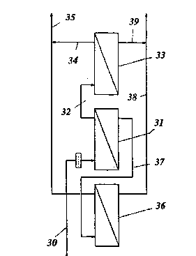
Fig. 3 shows an example of a multi-step membrane arrangement
which may be used on the implementation of the invention,
i.e., for the part which relates to membrane separation of
unwanted gases, disclosed herein as H2S, C02 and H20.
Untreated, separated gas from the cyclone separators (lla in
Fig. 4) flows through the pipeline 30 to a first membrane 31.
Thence the purified gas flows through the pipeline 32 to a
second membrane 33 for further purification/separation. Clean
20 gas is withdrawn through the pipline 34 and passes to the
pipeline 35, which conducts purified gas from a third membrane
36. This membrane separates gas from the C02, H2S, H20
enriched gas from the membrane 31. The enriched gas portion
including unwanted gases is conducted as shown from the first
membrane 31 to the third membrane 36 through a pipeline 37.
Clean gas passes from the third membrane 36 to the pipeline
35 and H2S, C02, H20 rich gas passes to the pipeline 38, to
which separated gas from the second membrane 33 is also
conducted through the pipeline 39.