Sélection de la langue

Search

Sommaire du brevet 2174044 

Énoncé de désistement de responsabilité concernant l'information provenant de tiers

Une partie des informations de ce site Web a été fournie par des sources externes. Le gouvernement du Canada n'assume aucune responsabilité concernant la précision, l'actualité ou la fiabilité des informations fournies par les sources externes. Les utilisateurs qui désirent employer cette information devraient consulter directement la source des informations. Le contenu fourni par les sources externes n'est pas assujetti aux exigences sur les langues officielles, la protection des renseignements personnels et l'accessibilité.

Disponibilité de l'Abrégé et des Revendications

L'apparition de différences dans le texte et l'image des Revendications et de l'Abrégé dépend du moment auquel le document est publié. Les textes des Revendications et de l'Abrégé sont affichés :

  • lorsque la demande peut être examinée par le public;
  • lorsque le brevet est émis (délivrance).
(12) Brevet: (11) CA 2174044
(54) Titre français: ATTACHE ET DISPOSITIF DE FIXATION DE CABLE
(54) Titre anglais: ATTACHMENT AND CABLE FASTENING DEVICE
Statut: Réputé périmé
Données bibliographiques
(51) Classification internationale des brevets (CIB):
  • F16G 11/10 (2006.01)
  • F16G 11/00 (2006.01)
(72) Inventeurs :
  • DE ANFRASIO, ANTOINE (Etats-Unis d'Amérique)
(73) Titulaires :
  • DE ANFRASIO, ANTOINE (Etats-Unis d'Amérique)
(71) Demandeurs :
  • DE ANFRASIO, ANTOINE (Etats-Unis d'Amérique)
(74) Agent: MACRAE & CO.
(74) Co-agent:
(45) Délivré: 2000-04-11
(22) Date de dépôt: 1996-04-12
(41) Mise à la disponibilité du public: 1996-10-14
Requête d'examen: 1997-07-21
Licence disponible: S.O.
(25) Langue des documents déposés: Anglais

Traité de coopération en matière de brevets (PCT): Non

(30) Données de priorité de la demande:
Numéro de la demande Pays / territoire Date
9504697 France 1995-04-13

Abrégés

Abrégé anglais


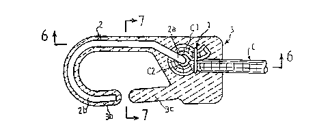
An attachment and cable fastening device. The device
has an elongate elastic cable folded over at least one of
its ends to form an eyelet. An metallic ring is crimped
around the elastic cable's folded over ends. A strong metal
hook with a frontwardly lying generally U-shaped front hook
portion and a bent end extremity is placed with its bent end
extremity fitted into the eyelet. A plastic covering is
formed around the folded over end of said elastic cable, the
metallic ring and the strong metal hook.

Revendications

Note : Les revendications sont présentées dans la langue officielle dans laquelle elles ont été soumises.


THE EMBODIMENTS OF THE INVENTION IN WHICH AN EXCLUSIVE PROPERTY
OR PRIVILEGE IS CLAIMED ARE DEFINED AS FOLLOWS:

1. An attachment and cable fastening device,
comprising:
an elongate elastic cable with a plurality of ends;
a plurality of strong metal hooks, each having a
forwardly lying front hook portion, one each of said strong
metal hooks being attached to each said end of said elongate
elastic cable by a crimping ring; and
a plastic covering permanently enveloping said ends of
said elastic cable, said crimping ring and said strong metal
hooks.

2. The attachment and cable fastening device of
claim 1, wherein said crimping rings are metallic and said
strong metal hooks have a rearwardly lying curved back portion,
said ends of said elongate elastic cable are bent over and said
crimping rings are crimped therearound to form an eyelet, and
a curved back part of said metal hooks are inserted into said
eyelet.

3. The attachment and cable fastening device of
claim 1, wherein said metal hooks are steel that have been
coated with a surface treatment to increase their traction.


4. The attachment and cable fastening device of
claim 1, wherein said metal hooks are formed of generally
flattened material.

5. The attachment and cable fastening device of
claim 1, wherein said metal hooks are formed of steel wire
which has a generally ovoid cross-section.

6. The attachment and cable fastening device of
claim 1, wherein said plastic covering contains an enlarged
portion in a vicinity of said crimping rings having lateral
bulges at a frontmost portion thereof, and a cavity to
accommodate a thumb and index finger of a user of the device.

7. The attachment and cable fastening device of
claim 1, wherein said forwardly lying front hook portions
extends frontwardly from a first side region of said plastic
covering and around and back to, but not contacting a second
side region of said plastic covering to define a hooking
capture region.

8. The attachment and cable fastening device of
claim 7, wherein said plastic covering further comprises a
flexible finger portion which extends forwardly from said


second side region of said plastic covering to be adjacent to
said front hook portion.

9. The attachment and cable fastening device of
claim 8, wherein said flexible finger portion is adapted to
lockably engage with a portion of said front hook portion.

10. The attachment and cable fastening device of
claim 9, wherein said plastic covering contains an enlarged
portion in a vicinity of said crimping ring having lateral
bulges at a frontmost portion thereof, and a cavity to
accommodate a thumb and index finger of a user of the device.

11. An attachment and cable fastening device,
comprising:
an elongate elastic cable folded over at least one of
its ends to form an eyelet;
a metallic ring crimped around the elastic cable's
folded over ends to maintain said eyelet;
a strong-metal hook with a frontwardly lying generally
U-shaped front hook portion and a bent end extremity, said bend
end extremity being adapted to be fitted into said eyelet; and
a plastic covering formed around and permanently
enveloping said folded over end of said elastic cable, said
metallic ring and said strong metal hook.


12. The attachment and cable fastening device of
claim 11, wherein said metal hooks are steel that has been
coated with a surface treatment to increase its traction.

13. The attachment and cable fastening device of
claim 11, wherein said metal hooks are formed of generally
flattened material.

14. The attachment and cable fastening device of
claim 11, wherein said metal hooks are formed of steel wire
which has a generally ovoid cross-section.

15. The attachment and cable fastening device of
claim 11, wherein said forwardly lying front hook portion
extends frontwardly from a first side region of said plastic
covering and around and back to, but not contacting a second
side region of said plastic covering to define a hooking
capture region.

16. The attachment and cable fastening device of
claim 15, wherein said plastic covering further comprises a
flexible finger portion which extends forwardly from said
second side region of said plastic covering to be adjacent to
said front hook portion.


17. The attachment and cable fastening device of
claim 16, wherein said flexible finger portion is adapted to
lockably engage with a portion of said front hook portion.

18. The attachment and cable fastening device of
claim 11, wherein said elongate elastic cable is folded over at
its two ends, and two metallic rings are fit thereon.

Description

Note : Les descriptions sont présentées dans la langue officielle dans laquelle elles ont été soumises.


- 217~0~


AlTACHMENT AND CABLE FASTENING DEVICE
BACKGROUND OF THE INVENTION
The invention concerns particularly the technical industry for
attachment and fastening devices similar to the type used for luggage elastic, rubber
shock absorbers, chest expanders... (sometimes hereinafter referred to as elastic
c~rd.
There are different versions of elastic shock cords and similar devices for
attachment, fastening, or hanging from an elastic cable that has at least one extremity
connected to an instrument type hook.
An example is the elastic shock cord in which the cable extremities are
simply equipped with a ring that has been crimped, whose extremities are thereafter
lodged into the shaft of the hook.
Under another version, the hook-end extremity forms a ring crimped on
the extremity of the cable, which all together can ultimately be covered with a suitable
plastic material.
While these types of popular elas~iacords are often times satisfactory,
they nonetheless do not exhibit a considerable resistance to traction. Indeed, when
there is more than 66-132 pounds (30 to 60 kilograms) of traction, either the hook
opens because it is made of ordinary steel, or the connector cable-ring or cable-hook
breaks.
In order to improve the quality of these elastic cords, I thought about
placing a buckle at the extremities of the cable, and crimping the ring or the hook-end
extremity behind this buckle. In this manner, the increased traction strength, if
substantial, would be enough to specifically comply with the new security standards,
for example in the areas of methods of holding cart merchandise or maintenance
garage rack tools.
The attachment and fastening device, under the invention, is in
accordance with these criteria in that it allows for traction effort in excess of

217~044


220 pounds (100 kilograms) in a cable composition that is similar to its predecessors.
One way to achieve these ends is that the attachment and fastening
device includes a combination of a buckle on the cable extremity crimped with a
metallic ring, a sturdy solid metallic hook fastened on the end to work with thebuckle on the cable, and a covering of the entire crimped buckle and hook with aplastic material made of good mechanical elements.
Another way to increase the device's traction resistance is that the
metallic hook is made of steel made of good mechanical elements that can undergoan appropriate surface treatment, or the hook can also be made with a flat plane or
ovoid section, or the plastic covering material can even be of a ~einforced resin.
Under the invention, we also tried to get a good handle on the
attachment and fastening device, without the risk of fingers slipping under the
traction strain. Therefore, the entire device is covered with and composed of
ergonomical properties, and in particular by an enlargement where the hook begins
which continues along its two large sides.
Those characteristics and others will emerge in the following
description.
BRIEF DESCRIPTION OF THE DRAWINGS
To determine the purpose of the invention without thereby limiting it,
in the pictures attached:
- Figure 1 is a perspective view which separately illustrates the end
buckle of the cable and the metallic hook of the invention.
- Figure 2 is a side view showing the end buckle of the cable assembled to
the metallic hook.
- Figure 3 is a cut view illustrating the covering of the entire end metallic
buckle-hook.

~ 21740~4


- Figure 4 is an exterior view similar to Figure 3.
- Figure S is a blueprint view corresponding to Figure 4.
- Figure 6 is a cut longitudinal view following lines 6 to 6 of Figure 3.
- Figure 7 is a cut transversal view following lines 7 to 7 of Figure 3.
-Figure 8 illustrates a variation model of the device according to the
invention, in particular the molded hook.
-Figure 9 illustrates another variation model in which the security
attachment works with the free end extremity of the hook.
DETAILED DESCRIPTION OF THE INVENTION
In order to give more concrete details about the invention's purpose, we
now describe it in a manner not limited to what is illustrated in the drawings.

The principal goal is to put together an assembly that is very resilient to
traction; the tests showed that in order to obtain worthwhile results, we need to
combine several solutions that we describe hereinafter below:
First of all, at the e~lrelluty or at both extremities of a cable (C), ~rerel ably
but not necessarily composed of several elastomer blen~le-l fibers coated with a textile
girdle, of the type named sandow elashc cord, a buckle (C1) is created that is crimped
with a surrounding metallic ring (1) by crushing the two fibers of the cable behind the
buckle (Figure 1).
In the eyelet (C2) of the buckle is the bended end extremity (2a) of a hook
(2) in metallic fiber (Figure 2), then the entire buckle (C1) - hook (2) is covered with a
plastic material (3).
As we can see in Figure 3, the very close connection between the plastic
coating material, the independent hook and the crimped buckle

-- 217904~


of the cable helps in large part to improve the traction resistance as compared to the
classic assemblies mentioned above.
In order to increase more the traction resistance, we also forsee the
creation of the hook (2) made of good steel mechanical elements with eventually a
surface quenching treatment followed by a tempering, thereby avoiding the opening
of the active part (2b) of the hook due to heavy exertion. We can also create the hook
with a flat plane (2c) or ovoid section as shown in Figure 7.
The covering (3) constituting a molding, can also be accomplished with
resin which increases even more the traction resistance.
This covering extends across a part of the massive rear (3a) surrounding
mostly the curved end (2a) of the hook, the buckle (Cl) and the crimping ring (1), then
a part (3b) in a hook shape surrounding the hook (2) and its counter part (2b) and,
eventually a flexible security attachment (3c) coming from the massive rear (3a),
opposite the hook start (3b) and spreading out in alignment with the free extremity of
the active part of the hook, leaving between them a space for passing of the element
onto which must attach the invention device.
To avoid any unreasonable slipping of the user's fingers under the
traction strain, I also foresaw to create the massive part (3a) of the covering into an
ergonomic shape, specifically, as we can see on Figures 4, 5 and 6, with some lateral
bulge (3al-3a2) at the hook's start level and following at least its two big sides. These
bulges constitute natural abutments for the thumb and index finger which become
lodged into the cavities or depressions (3a3 - 3a4) thereby formed at the rear of the
bulges.
For certain uses, it is necessary to arrange the massive part (3a) of the
covering in support of or very close to a surface and to anchor the hook below the said
surface.

217~04~


In order to do this, I foresaw as illustrated on Figure 8 to reverse the
direction of the active part of the hook (2b-3b), which is thus moved forward ascompared to the massive part (3a), instead of being in its prolongation.
In another variation illustrated on Figure 9, the security attachment (3c)
coming from the molding is relatively rigid and introduces at its free extremity a
hook shape (3c.1) to blend with the free extremity of the molded hook (3b) thereby
creating an additional hooker. (3b.1).
The advantages are seen from the description. I _ underline once again
that there has been a very significant increase of traction resistance due to the
combination of the links between the cable and hook, and to the materials utilized, as
well as the good control of the attachment devices with ergonomical forms that were
judiciously conceived.

Dessin représentatif
Une figure unique qui représente un dessin illustrant l'invention.
États administratifs

Pour une meilleure compréhension de l'état de la demande ou brevet qui figure sur cette page, la rubrique Mise en garde , et les descriptions de Brevet , États administratifs , Taxes périodiques et Historique des paiements devraient être consultées.

États administratifs

Titre Date
Date de délivrance prévu 2000-04-11
(22) Dépôt 1996-04-12
(41) Mise à la disponibilité du public 1996-10-14
Requête d'examen 1997-07-21
(45) Délivré 2000-04-11
Réputé périmé 2002-04-12

Historique d'abandonnement

Il n'y a pas d'historique d'abandonnement

Historique des paiements

Type de taxes Anniversaire Échéance Montant payé Date payée
Le dépôt d'une demande de brevet 0,00 $ 1996-04-12
Requête d'examen 400,00 $ 1997-07-21
Taxe de maintien en état - Demande - nouvelle loi 2 1998-04-14 50,00 $ 1998-04-14
Taxe de maintien en état - Demande - nouvelle loi 3 1999-04-12 50,00 $ 1999-04-08
Taxe finale 150,00 $ 2000-01-12
Taxe de maintien en état - brevet - nouvelle loi 4 2000-04-12 250,00 $ 2000-04-26
Titulaires au dossier

Les titulaires actuels et antérieures au dossier sont affichés en ordre alphabétique.

Titulaires actuels au dossier
DE ANFRASIO, ANTOINE
Titulaires antérieures au dossier
S.O.
Les propriétaires antérieurs qui ne figurent pas dans la liste des « Propriétaires au dossier » apparaîtront dans d'autres documents au dossier.
Documents

Pour visionner les fichiers sélectionnés, entrer le code reCAPTCHA :


Pour visualiser une image, cliquer sur un lien dans la colonne description du document. Pour télécharger l'image (les images), cliquer l'une ou plusieurs cases à cocher dans la première colonne et ensuite cliquer sur le bouton "Télécharger sélection en format PDF (archive Zip)" ou le bouton "Télécharger sélection (en un fichier PDF fusionné)".

Liste des documents de brevet publiés et non publiés sur la BDBC .

Si vous avez des difficultés à accéder au contenu, veuillez communiquer avec le Centre de services à la clientèle au 1-866-997-1936, ou envoyer un courriel au Centre de service à la clientèle de l'OPIC.


Description du
Document 
Date
(yyyy-mm-dd) 
Nombre de pages   Taille de l'image (Ko) 
Page couverture 1996-07-17 1 15
Abrégé 1996-07-17 1 15
Description 1996-07-17 5 192
Revendications 1996-07-17 5 116
Dessins 1996-07-17 3 53
Page couverture 2000-03-02 1 30
Dessins représentatifs 1999-06-29 1 7
Dessins représentatifs 2000-03-02 1 8
Revendications 1997-11-28 5 124
Cession 1996-04-12 4 111
Poursuite-Amendment 1997-07-21 10 274
Correspondance 2000-01-12 1 32