Note : Les descriptions sont présentées dans la langue officielle dans laquelle elles ont été soumises.
~741~
~ j , .,
--2--
BACRGROUND OF THE INVENTION
The present invention relates to prosthetic devices
and more particularly to an improved liner for prosthetic
devices including artificial limbs that also may be
articulable or bionic.
An amputee is a person who has lost part of an
extremity or limb such a leg or arm which commonly may be
termed as a residual limb. Residual limbs come in
various sizes and shapes with respect to the stump. That
is, most new amputations are either slightly bulbous or
cylindrical in shape while older amputations that may
have had a lot of atrophy are generally more conical in
shape. Residual limbs may further be characterized by
their various individual problems or configurations
including the volume and shape of a stump and possible
scar, skin graft, bony prominence, uneven limb volume,
neuroma, pain, edema or soft tissue configurations.
Referring to FIGS. 1 and 2, a below the knee
residual limb 10 is shown and described as a leg 12
having been severed below the knee terminating in a stump
14. In this case, the residual limb 10 includes soft
tissue as well as the femur 16, knee joint 18, and
severed tibia 20 and fibula 22. Along these bone
structures surrounded by soft tissue are nerve bundles
and vascular routes which must be protected against
external pressure to avoid neuromas, numbness and
discomfort as well as other kinds of problems. A below
the knee residual limb 10 has its stump 14 generally
characterized as being a more bony structure while an
above the knee residual limb may be characterized as
including more soft tissue as well as the vascular routes
and nerve bundles.
~17~15~
Referring to FIG. 3, amputees who have lost a part
of their arm 26, which terminates in a stump 28 also may
be characterized as having vascular routes, nerve bundles
as well as soft and bony tissues. The residual limb 10
includes the humerus bone 30 which extends from below the
shoulder to the elbow from which the radius 34 and ulna
36 bones may pivotally extend to the point of severance.
Along the humerus bone 30 are the biceps muscle 38 and
the triceps muscle 40 which still yet may be connected to
the radius 34 and the ulna 36, respectively.
In some respects, the residual limb amputee that
has a severed arm 26 does not have the pressure bearing
considerations for an artificial limb but rather is
concerned with having an artificial limb that is
articulable to offer functions typical of a full arm,
such as bending at the elbow and grasping capabilities.
An individual who has a paralyzed limb would also have
similar considerations wherein he or she would desire the
paralyzed limb to have some degree of mobility and thus
functionality.
Historically, artificial limbs typically used by a
leg amputee were for the most part all made out wood such
an Upland Willow. The limbs were hand carved with
sockets for receiving the stump 14 of the residual limb
10. Below the socket would be the shin portion with the
foot below the shin. These wooden artificial limbs were
covered with rawhide which often were painted. The
sockets of most wood limbs were hollow as the limbs were
typically supported in the artificial limb by the
circumferential tissue adjacent the stump 14 rather than
at the distil end of the stump 14.
217~
. , ~
--4--
Some artificial limbs in Europe were also made from
forged pieces of metal that were hollow. Fiber
artificial limbs were also used which were stretched
around a mold afterwhich they were permitted to dry and
cure. Again, these artificial limbs were hollow and
pre~ty much supported the residual limb about the
circumferential tissue adjacent the stump 14.
All of these various artificial limbs have sockets
to put the amputee's stump 28 thereinto. There are
generally two categories of sockets. There are hard
sockets wherein the stump goes right into the socket
actually touching the socket wall without any type of
liner or stump sock. Another category of sockets is a
socket that utilizes a liner or insert. Both categories
of sockets typically were opened ended sockets were they
had a hollow chamber in the bottom and no portion of the
socket touched the distil end of the stump 14. So, the
stump was supported about its circumferential sides as it
fits against the inside wall of the sockets.
These types of sockets caused a lot of shear force
on the stump 14 as well as had pressure or restriction
problems on the nerve bundles and vascular flow of fluid
by way of the circumferential pressure effect of the
socket on the limb. This pressure effect could cause a
swelling into the ends of the socket where an amputee may
develop severe edema and draining nodules at the end of
their stump 14.
With time, prosthetists learned that by filling in
the socket's hollow chamber and encouraging a more total
contact with the stump and the socket, the swelling and
edema problems could be eliminated. However, the
problematic tissue configurations, such as bony
~1741 51
-- 5
prominences, required special consideration such as the
addition of soft or pliable materials to be put into the
socket.
Today, most artificial limbs are constructed from
thermoset plastics such a polyester resins, acrylic
resins, polypropylenes and polyethylenes, which are
perhaps laminated over a nylon stockinette which also may
be impregnated by the various resins.
In the past, most artificial limbs were suspended
from the amputee's body by some form of pulley, belt or
strap suspension often used with various harnesses and
perhaps leather lacers or lacings. Another method of
suspending artificial limbs is known as the wedge
suspension wherein an actual wedge is built into the
socket which is more closed at its top opening. The
wedge in the socket cups the medial femoral condyle or
knuckle at the abductor tubical. Yet another form of
suspension is referred to as the shuttle system or a
m~h~nical hookup or linkup wherein a thin suction liner
is donned over the stump that has a docking device on the
distal end which mechanically links up with its
cooperative part in the bottom of the socket chamber.
Sleeve suspensions were also used wherein the amputee may
use a latex rubber tube which forms into a rubber-like
sleeve which would be rolled on over both the top of the
artificial limb and onto the amputee's thigh. The sleeve
suspensions have been used in combination with other
forms of suspension techniques.
The first artificial limb socket liners were made
with molded horsehide leather covered with strips from
extruded sheets of rubber glued to the leather as the
liner was built up over a positive cast of the residual
~ ~17~
limb. As before, stump socks typically made of cotton or
wool were used with these first liners as well as with
the earlier hard sockets.
The next major socket liner was formed from an
expanded foam such as polyurethane foam as sold by
Durr-Fillauer Medical, Inc. of Chatanooga, Tennessee.
After a positive cast was made of the residual limb, a
cone-like structure of the hard foam plastic was formed
and heated. Next, the expanded foam was pulled over the
cast of the residual limb in an effort to form it to the
limb after which the foam was cooled and its shape was
retained over the positive cast. Thereafter, a hard
shell socket could be built or laminated over the liner
from which a shin and foot of the artificial limb could
be attached.
Another type of socket liner was made from a
combination of silicone and gauze being sandwiched in
between two pieces of leather. However, this type of
liner had problems in that it was much too rigid,
wouldn't stretch and eventually loosened up and migrated
thereby becoming ineffective.
The next group of socket liners were made from the
impregnation of a cotton stockinette with silicone resins
formed over a positive cast of the residual limb. The
problem with these types of liners is that the silicone
could not migrate or stretch and was often short lived in
that sweat from the residual limb would break down the
silicone and create pungent and unsanitary conditions.
Another type of silicone liner without the
impregnated stockinette has been utilized to create
suction about the residual limb for use in combination
217
.
with perhaps a shuttle or mechanical link up device with
the socket. However, these types of liners offered no
yield or cushion and required the wearing of stump
socks.
While some of these devices addressed some of the
problems associated with prosthetics, none of the
artificial limbs, liners and sockets, individually or in
combination offered a prosthesis that presented a total
contact relationship with the residual limb; absorbed and
dissipated shear, shock and mechanical forces transmitted
to the limb tissues by the artificial limb; controlled
perspiration of the residual limb; controlled residual
limb volume; and, promoted equal weight distribution
while having a long life expectancy.
There is a need for a liner to be used with
prosthetic devices that will offer total contact
relationship with the residual limb; provide hypobaric
suction suspension with a sticky or tacky surface
condition; absorb and dissipate shock, mechanical and
shear forces typically associated with ambulation,
twisting and turning and weight bearing with an
artificial limb; control perspiration; control residual
limb volume by way of even weight distribution; and offer
relief for the various tissue configurations that plague
residual limbs while yet being of long life.
8U~MARY OF THE lNV~h llON
A visco-elastic polymer liner for use in donning
over a residual limb and fitting within the socket of an
artificial limb. The liner is shaped to have its cavity
formed with a volume and shape less than a volume and
~17~
. ,
shape of the residual limb for both tension and tissue
configuration relief while the liner has an outer surface
formed with a volume and shape greater than the volume
and shape of the artificial limb socket for relief of
certain tissue configurations and to create weight
bearing, relief and compression areas on and in the liner
to absorb and dissipate shock, shear and mechanical
forces through the liner otherwise transmitted to the
residual limb. The liner may have imbedded on its inner
cavity side electrodes adjacent muscles that are
sensitive to the muscle action potentials to generate
signals to a power source to move an articulable
artificial limb. The liner may take the shape of a tube
to be donned over a paralyzed limb similarly having
electrodes imbedded in its inner cavity side adjacent
neuromuscular junctions which are connected to a muscle
action potential generator to activate flexion and
extension of the paralyzed limb. A method for making the
liner is also claimed which comprises the making of a
positive model of the residual limb, reducing the model,
forming the liner about the reduced model and laminating
a hard socket over a reduced model of the liner.
A principal object and advantage of the present
liner is that it provides total environment control about
the tissue of the residual or paralyzed limb by way of a
total contact relationship between the liner and the
tissue.
Another advantage and object of the present
invention is that it has a tacky or sticky surface which
permits the liner to actually tack up to the limb tissue
and provide a hypobaric suction when used as a socket
~ 217~
liner which eliminates a bulky suspension apparatus as
well as control on the residual limb volume and perspiration.
Another object and advantage of the present
invention is that the liner, when utilized with an
artificial limb socket, totally absorbs and dissipates
shock, shear and mechanical forces which are normally
transmitted directly to the tissues of the residual limb
from the artificial limb during weight bearing,
ambulation, twisting and turning.
Another advantage and object of the present
invention is that the total contact relationship between
the residual limb tissues, the liner and the artificial
limb socket permits equal weight distribution resulting
in lower pounds per square inch pressure on limb tissues
thereby permitted extended comfortable wear of an
artificial limb heretofore not known.
Another advantage and object of the present
invention is that the visco-elastic, energy-absorbing,
flexible polymer liner will stretch, move or creep
internally while having a memory for the liner to return
to its original shape.
Another advantage and object of the present
invention is that the liner when used with a socket and
artificial limb may be used with any means of suspension
although suction socket with a mechanical link-up appears
advantageous.
Another principal object and advantage of the
present liner is that the polyurethane elastomer material
permits additional buildup and removal of material for
~17~51
, ~
-- 10 --
adjustment of the liner over time that is easy and simple
without the need of additional catalysts.
Yet another advantage and object of the present
invention is that the liner is durable for long wear and
is readily cleanable with soap and water to provide an
odor free clean environment for a residual limb or a
paralyzed limb.
A final principal object and advantage of the
present invention is that an amputee with a residual limb
may simply don the liner and place the limb within a
socket without the need of additional padding or stump
socks which has normally been the case until this invention.
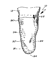
BRIEF DESCRIPTION OF T~E DRAWING8
FIG. 1 is a side elevational view of the tissue and
skeletal structure of an amputee's residual limb;
FIG. 2 is a front elevational view of a residual
limb with a volume and shape and the skeletal structure
visible while donning a light cotton marking sock;
FIG. 3 is a side elevational view of a residual
limb in the form of an amputated arm showing the skeletal
and muscular structure of the residual limb;
FIG. 4 is a front elevational view of a plaster
wrap or cast of the residual limb of FIG. 2 constituting
a negative model of the residual lim~;
FIG. 5 is a front elevational view of a plaster
positive model of the residual limb of FIG. 2 made from
the mold of FIG. 4.
~17~151
--11--
.
FIG. 6 is a reduced positive model of the residual
limb of FIG. 2 formed by reduction of the positive model
of FIG. 5 having a volume and shape less than that of the
positive model;
FIG. 7 is a front elevational view of the reduced
positive model or prototype of FIG. 6 mounted in a jig
with a liner filler medium stretched thereover;
FIG. 8 is a cross-section take along lines 8-8 of
FIG. 7;
FIG. 9 is a front elevational view of the reduced
positive model of the residual limb with a second plaster
wrap over the filler medium and reduced positive model of
the limb as shown in FIG. 7;
FIG. 10 is a cross sectional view taken along
lines 10-10 of FIG. 9;
FIG. 11 is an elevational view of the jig for
keying the second plaster wrap of FIG. 9 about the
reduced positive model of the residual limb of FIG. 6
with the base of the jig partially broken away;
FIG. 12 is a front elevational view of the residual
limb donning the liner of the present invention with a
light cotton marking sock thereover;
FIG. 13 is a front elevational view of the residual
limb with liner and cotton sock of FIG. 12 having a third
plaster wrap thereover which is a negative model of the
socket;
FIG. 14 is a plaster cast or positive model of the
socket made from the plaster wrap of FIG. 13;
~174151
-12-
FIG. 15 is a reduced positive model of the socket
made from the model of FIG. 14 having a volume and shape
less than that of the positive model of FIG. 14;
FIG. 16 is a side elevational view of the socket
and remaining parts of an artificial limb laminated or
built about the reduced positive model socket of FIG. 15;
FIG. 17 is an elevational view of a mechanical
link-up, hook-up or interlocking linkage for securing the
residual limb liner to an artificial limb;
FIG. 18 is a side elevational view of an amputee's
residual limb donning a bionic or articulable limb
partially broken away in an extension position;
FIG. 19 is the residual limb and artificial limb of
the FIG. 18 in its flexion position; and
FIG. 20 is an elevational view of a paralyzed upper
limb or arm donning a bionic harness for actuating
paralyzed muscle movement.
DE8CRIPTION OF THE PREFERRED EMBODIMENT
Referring to FIGS. 1-5, normally amputees are seen
by the prosthetist post operatively after they have had
primary wound healing. While the residual limb 12
consists of either a leg 12 or an arm 26, the amputees
are evaluated for the size and shape of their stump 14 or
28 with additional considerations given to scar, skin
graft, bony prominence, uneven limb volume, neuroma,
pain, edema or soft tissue configurations. Through
conversations, the amputees are also evaluated as to what
their activity levels are.
~74~
-13-
Next, a single ply thin cotton casting sock 42 is
then placed over the residual limb 10. Certain tissue
configuration locations as well as pressure sensitive
areas are then marked with indelible ink 45 on the
casting sock 42. Next.an orthopedic plaster wrap 44 that
has been dipped in water is formed about the residual
limb. After the wrap has been permitted to set and
harden, the residual limb 10 is withdrawn from the
plaster wrap 44 leaving the casting sock 42 adhered to
the plaster wrap. Various separating or releasing media
may be used on the residual limb before donning of the
casting sock 42, such as a baby powder, vaseline or
petroleum jelly, which assists in the removal of the
residual limb from the plaster wrap which constitutes the
first negative mold of the residual limb 10.
The plaster wrap 44 or first negative mold of the
residual limb 10 is next filled with plaster, such as
dental plaster, and a centrally located mandrel or pipe
48 is positioned within the plaster cast for later key
positioning within a jig or for simply supporting the
plaster cast 46 after it is removed from the plaster
wrap 46. Again, known separating agents may be used
between the plaster wrap 44 and the plaster cast 46.
The plaster cast 46, once removed from the plaster
wrap 44, constitutes the original prototype and first
positive model 46 of the residual limb 10. As can be
seen in the original prototype 46 in FIG. 5, the ink
marks 43 readily transfer over to the plaster cast 46 for
consideration of the residual limb's volume and shape,
category and tissue configurations, such as a scar, skin
graft, bony prominence, uneven limb volume, neuroma,
edema, pain, pressure sensitive areas and soft tissue.
Certain of these areas will require the liner 90 to have
2~7~
-14-
varying degrees of thickness and density to accommodate
these considerations.
Thus, referring to FIG. 6, the original
prototype 46 of FIG. 5 is reduced or built up to form the
reduced positive model of the residual limb 50. The
reduction of this positive model will result in a tension
factor on the liner 90 when it is stretched and donned by
the residual limb 10, which is a little larger than the
volume and shape of the inner cavity 91 of liner 90, as
will become clear.
Applicant presently contemplates that computer
controlled mills will assist the prosthetists in either
shaving off or melting off in a more accurate fashion
portions of the original prototype 46 to create the
reduced positive model 50 of the residual limb lO.
It is important that the reduced positive model not
be reduced in size too much as to create a shear force
upon the tissues of the residual limb lo creating
problems.
The prosthetist must next consider what thickness
he or she wishes the liner 90 to have. Normally the
liner 90 is between five-eights to three-quarters of an
inch thick at the stump end 14 and roughly about
three-sixteenths to a quarter of an inch thick around the
entire residual limb. Additional considerations would
include making the liner thinner where specific weight
bearing areas of the residual limb would be located as
well as making certain areas of the liner 90 thicker to
displace and compress the liner 90 in a manner to
disperse pressure away from certain tissue
configurations. It is also known that where a person is
-
~ 741~
-15-
more fleshy, such as in the femur 16 area in the above
the knee amputation, the liner 90 would have generally
thinner dimensions to add weight bearing areas to the
soft tissues. Where there exists a bony prominence, such
as in the below the knee amputee, the liner 90 may be a
little thicker to disperse the weight bearing areas.
With these considerations in mind, the prosthetists
takes the reduced positive model 50 with its mandrel 48
and mounts the model 50 in jig 53 suitably upside down
for ease of working as seen in FIG. 7. Thereafter, a
filler medium, such a thermoplastic foam 52, is then
built on and about the reduced positive model 50 which
actually represents the thickness of the liner 90 to be
made. The filler medium 52 may be a wool stump sock or
various types of expanded thermoplastic foams will also
work well. The thermoplastic foams 52 can be readily
formed into the shape of a cone and heated. Thereafter,
the heated foam 52, which becomes flexible is formed over
the reduced positive model 50 and perhaps vacuumed
thereto by way of an evacuated plastic bag being placed
over the thermoplastic foam 52. Sheets of the foam 52
that are formed into cone-like structures are available
from previously mentioned Durr-Fillauer Medical, Inc. of
Tennessee.
As stated, the expanded thermoplastic foam, such as
a polyurethane foam or other such expanded foam products
such as polyethylene or polypropylene, represents the
space where the liner 90 will be. Thus, additional
pieces of the foam 52 may be added to the reduced
positive model 50, such as the distal end of the stump 14
to form a distal end cap as well as or other areas which
may require additional thicknesses due to tissue
configurations.
After a releasing or separating medium has been
applied to the thermoplastic foam 52, a second plaster
2~7~
.
-16-
wrap 54 is applied over the foam 52 thereby creating a
second enlarged negative mold 54 as shown in FIGS. 9
and lo. Thus, the reduced positive model 50 of the
residual limb 10 is in a predetermined spaced
relationship with the second plaster wrap 54 by way of
the thermoplastic foam interface 52.
Referring to FIG. 11, the second plaster wrap 54
has an adaptor block 60, suitably made of wood or foam,
affixed to its bottom such as by glue.
-
The block 60 appropriately has a threaded aperture62 through which a wing nut screw 64 rotatably may pass.
The plaster wrap 54 with its adapter block 6 is now ready
for placement within the transfer jig 70. Transfer
jig 70, as shown in FIG.7, is a memory device for
repeatedly keying the reduced positive model 50 and the
second plaster wrap 54 should additional liners 9o be
required to be built over time. Transfer jig 70 includes
a horizontal plate 72 with keying connectors or ridges 74
which will permit indexing the adaptor block 60 therein
for repeated and exact placement of the second plaster
wrap 54 upon the transfer jig 70.
Transfer jig 70 also includes a calibrated vertical
support 76 having a first collar 78 which adjusts
vertically and horizontally and may be secured with
respect to those two planes by collar fastener 80. First
collar 78 and second collar fastener 82 support, hold and
key a horizontal extension 84 which has a second
horizontal collar 86 located at its opposing end. The
second collar 86 similarly has a collar fastener 88 for
locking the collar 86 about mandrel 48.
By this arrangement, reduced positive model 50 of
residual limb 10 and the second plaster wrap 54, which is
~17~
-17-
the negative mold of the socket may be keyed together
repeatedly in the exact relationship so that the liner 90
may be repeatedly poured and shaped into the same shape.
With the thermoplastic foam 52 removed from between
the reduced positive model 50 and the second plaster
wrap 54, the liner 90 in its liquid and moldable form may
be introduced into the enlarged negative mold 54.
However, the liquid may first be subjected to vacuum,
such as in a desiccator, to draw out excess gases and
~ubbles. Urethane liner 90 is suitably made from a
visco-elastic polymer which is energy absorbing and
flexible exhibiting a flowability or internal movement
character with recovery of shape or memory. Applicant
has found that a polyurethane elastomer is suitably
appropriate in that it is further washable, durable,
bacterialstatic and fungistatic. Urethanes are
technically called a carbamate ester which is made from a
combination of isocyanates and alcohols. More
definitively, applicant has found that an aromatic
diisocyanate and elastisizing polyols, such as diols or
triols, form suitably urethanes or polyurethanes.
Applicant has found that a preferable polyurethane
includes the combination of an antioxydant with free
toluene diisocyanate and a blend of polyether polyols
with bismuth carboxylate. These components are
commercially available from Rieckens Orthodics
Laboratories of 401 North Green River Road, Evansville,
Indiana 47715 and has been used in the past as sole
material or inlay for use with shoes. Although energy
absorbing polymers have been used as sole or inlays for
shoes, they have never been utilized in the context of
the present invention or prosthetic.
2~7~
~ . , .
-18-
Applicant has also found that vinyl resins or
moldable thermoplastics exhibiting visco-elastic polymer
qualities, energy absorption, flexibility, flowability
and recovery also will work in forming liner 90.
once the diiosocyanate and polyols components have
been mixed together forming viscous fluid with the
appropriate and predetermined durometer, the fluid is
poured into the second plaster wrap 54. The reduced
positive model 50 of the residual limb 10 is then placed
into the second plaster wrap 54 and keyed into the
transfer jib 70 as if thermoplastic foam 52 was still
interfaced between the model 50 and the wrap 54. A
releasing agent, such as a silicone base mold separator,
may be utilized between the wrap 54 and the model 50 so
that the liner 90 will readily separate after be
permitted to set and cure after one or two hours.
Separators are also available from Riechens Orthodic
Laboratories.
Referring to FIGS. 12-16, the prosethistist next
has the amputee don the urethane liner 90 over his or her
residual limb 10 after the urethane liner 90 has been
cleaned up and washed with soap. If the polyurethane
liner 90 is of extensive length, the amputee may need a
wetting agent such as a petroleum jelly which will
readily dissipate. Otherwise, the liner 90 is slid or
rolled onto the amputee's residual limb 10. Should the
liner 90 require some build up, hte freshly mixed
components will readily adhere to the liner 90.
Thereafter, another single ply thin cotton casting
sock 93 is then placed over the liner 90 which is marked
with the indelible ink 94 for a second consideration of
certain previously mentioned tissue configurations such
~741~1
--19--
as bony prominences, pressure areas and scar problems.
This step is necessary because once the liner 90 is
donned over the residual limb 10 with some degree of
tension, some of the relief, shape and volume adjustments
previously made become dissipated.
Thereafter, a third plaster wrap 96 or a negative
model of the artificial limb socket 104 is then made
about the residual limb 10 with the liner 90 and marked
up casting sock 93 thereon.
After the third plaster wrap 96 has cured and the
residual limb 10, liner 90 have been removed from the
third plaster wrap 96 or negative model of the socket, a
plaster cast or positive model of the socket 98 is made
from dental plaster. Suitably a mandrel 100 is placed in
the plaster 98 to assist in construction of the socket
104. As seen in FIG. 14, a positive model of the socket
98 has the ink marks 94 for certain reduction and build
up considerations for various tissue configurations and
so on.
Next, the positive model of the socket 98 is milled
or shaved to create a reduced positive model of the
socket 102 which is necessary to create weight bearing
areas and compression upon the liner against the inner
cavity 91 of the liner 9o on the residual limb and upon
the outer surface ~2 of the liner 90 upon the socket 104.
Referring specifically to FIG. 16, the artificial
limb 110 includes its socket 104, shin 106 and foot 108.
The limb 110 may be constructed by way of polyester or
acrylic resins laminated over nylon stockinettes or by
way of thermoset plastics including polypropylene and
polyethylene. The artificial limb 110 may use various
~74~
-20-
suspension techniques as mentioned. Once the socket 104
has been formed by lamination over the reduced positive
model of the socket 102, the artificial limb 110 is most
suitable for total contact hypoberic suction shuttle
suspension as shown in FIG. 17. By this arrangement, the
liner 122 is donned by the artificial limb and placed
within socket 124. A releasably mechanical interlocking
hookup or linkage 126 includes a ring 128 supported by a
mounting means in the liner and a pin 130 mounted in the
socket adjacent the shin. As previously stated, a
sleeve 132 may also be placed over the artificial
limb 120 and the leg 10.
The visco-elastic, energy absorbing, flexible
polymer liner of the present invention has applications
beyond that of merely being a total contact hypoberic
suction, equal weight distribution socket liner. That
is, the polyurethane liner, which readily tacks up to the
skin of the human body to the point of almost actually
becoming part of the skin readily permits the proper
location of electrodes for use and application of bionic
artificial limbs or the application of creating movement
of paralyzed limbs.
Referring to FIGS. 18 and 19, the application of
the present invention in a bionic artificial limb or
arm 140 will be explained. The amputee's arm 26 consists
of a stump 28 below the elbow 32 wherein the radius 34
and ulna 36 bones have been severed. The amputee has
normal and innervated bicep and tricep muscles 38 and 40
along the humerus with the exception that their lower
most connection to the radius and ulna, which have been
severed, provide no lever for these muscles to permit a
function.
~74~5~
-21-
Consequently, a bionic or articulable artificial
arm 140, as is known, typically would have a moveable
hook or hand 142 and a pivotally mounted motor driven
forearm 144 connected to the above elbow socket section
146. The socket section 146 has a pivot gear 148. The
polyurethane liner 150 of the present invention includes
an inner cavity 151 which has a biceps electrode 152 and
a triceps electrode 154. The electrodes 152 and 154
touch the skin and lie over the muscles 38 and 40 in a
predetermined location to monitor muscle action
potential. The electrodes 152 and 154 are then wired 156
through the liner 150 to touch plates 157 which are
further wired into the bionic arm 140. Signals from the
electrodes 152 and 154, which sense muscle action
potentials, are amplified and relayed to a forearm 144
control motor 158 which operates gear 160, all of which
are powered by battery 162.
In operation, the amputee consciously flexes his
biceps muscle 38. The muscle action potential is then
sensed by bicep electrode 152 after which it is relayed
and amplified to engage motor 158 and gear 160 to drive
the forearm portion 144 of bionic arm to a flexion
motion. When the amputee wishes to have the forearm 144
move into an extension or downward motion, the amputee
simply flexes his or her tricep muscles 40. The muscle
action potential is then sensed by triceps electrode 154
which similarly engages motor 158 and gear 160 in reverse
operation to move the forearm 144 downwardly.
The liner 150 of the present invention permits this
operation with repeated accuracy due to the liners
construction, location of the electrodes 152 and 154 and
wires 157 within the liner by way of forming the liner as
previously stated. The exact construction and donning of
217~
_ I . . .
-22-
the liner 150 will assure that electrodes 152 and 154 are
repeatedly placed over the proper location on the
amputee's skin and wires 156 will engage or touch plates
157.
Referring to FIG. 20, the liner of the present
invention has application for individuals who have a
paralyzed limb 170 wherein the paralysis is due to a
disconnection along the nerve pathways between the brain
and the muscle. In other words, the muscles 38 and 40,
once properly stimulated, will permit flexion and
extension of the paralyzed individuals's forearm.
Initially the proper locations to stimulate the
bicep and tricep muscles 38 and 40 must be predetermined
by known means, such as a "Tens device." Thereafter, a
polyurethane liner or tube 172 is formed as previously
disclosed herein having an inner wall 73. The bicep and
tricep electrodes and 174 and 176 are then placed within
the liner during its formation with connection wires
178. wires 178 are connected to a bionic harness 179 as
shown. The electrodes 174 and 176 are connected by way
of the wires 178 to a muscle action potential generator
180 which receives signals from amplifier 184 and limb
flexion or extension signal receiver 186, all of which
are powered by battery 182. When a flexion or extension
signal is received by the receiver 186, a muscle action
potential is discharged at the electrodes 174 or 176
likely located near a neuromuscular junction which will
initiate either flexion or extension.
Again, it is the unique method of construction and
materials from which the present liner is made which
permits exact location of electrodes on a repeated basis
on an individual's skins together with the tacking up of
~1~41~1
~ . ~ .,
-23-
the liner upon the skin no matter what the individual's
position or activity level that permits the liner to be
readily applicable to bionics or robotics.
The present invention may be embodied in other
specific forms without departing from the spirit or
essential attributes thereof; therefore, the illustrated
embodiment should be considered in all respects as
illustrative and not restrictive, reference being made to
the appended claims rather than to the foregoing
description to indicate the scope of the invention.