Sélection de la langue

Search

Sommaire du brevet 2174167 

Énoncé de désistement de responsabilité concernant l'information provenant de tiers

Une partie des informations de ce site Web a été fournie par des sources externes. Le gouvernement du Canada n'assume aucune responsabilité concernant la précision, l'actualité ou la fiabilité des informations fournies par les sources externes. Les utilisateurs qui désirent employer cette information devraient consulter directement la source des informations. Le contenu fourni par les sources externes n'est pas assujetti aux exigences sur les langues officielles, la protection des renseignements personnels et l'accessibilité.

Disponibilité de l'Abrégé et des Revendications

L'apparition de différences dans le texte et l'image des Revendications et de l'Abrégé dépend du moment auquel le document est publié. Les textes des Revendications et de l'Abrégé sont affichés :

  • lorsque la demande peut être examinée par le public;
  • lorsque le brevet est émis (délivrance).
(12) Brevet: (11) CA 2174167
(54) Titre français: APPAREIL SERVANT A EMPECHER LA CONDENSATION DANS LES MACHINES SERVANT AU TRAITEMENT DE BANDES DE MATERIAU
(54) Titre anglais: APPARATUS FOR PREVENTING CONDENSATION IN MACHINES PROCESSING A WEB OF MATERIAL
Statut: Périmé et au-delà du délai pour l’annulation
Données bibliographiques
(51) Classification internationale des brevets (CIB):
  • B41F 23/04 (2006.01)
  • B41F 13/00 (2006.01)
(72) Inventeurs :
  • KIEFABER, DREW E. (Etats-Unis d'Amérique)
  • RUMMLER, JEFFREY R. (Etats-Unis d'Amérique)
(73) Titulaires :
  • HEIDELBERG WEB SYSTEMS, INC.
(71) Demandeurs :
  • HEIDELBERG WEB SYSTEMS, INC. (Etats-Unis d'Amérique)
(74) Agent: DENNISON ASSOCIATES
(74) Co-agent:
(45) Délivré: 2000-02-29
(22) Date de dépôt: 1996-04-15
(41) Mise à la disponibilité du public: 1996-10-26
Requête d'examen: 1996-04-15
Licence disponible: S.O.
Cédé au domaine public: S.O.
(25) Langue des documents déposés: Anglais

Traité de coopération en matière de brevets (PCT): Non

(30) Données de priorité de la demande:
Numéro de la demande Pays / territoire Date
08/427775 (Etats-Unis d'Amérique) 1995-04-25

Abrégés

Abrégé anglais


The present invention concerns an apparatus for preventing condensation
in machines for processing web-like material, and in particular an apparatus forpreventing condensation on the safety guard of a printing press. The apparatus
includes components of a processing unit, and elements assigned to the
components to maintain the surface temperature of the components above the
dew point of the surrounding air.

Revendications

Note : Les revendications sont présentées dans la langue officielle dans laquelle elles ont été soumises.


Claims
1. An apparatus for preventing condensation in machines processing a web-
like material, comprising:
at least one component arranged within a processing unit; and
means for increasing a temperature of said at least one component,
to thereby to reduce a difference between a temperature of said at least
one component and a temperature of air surrounding said at least one
component.
2. The apparatus of claim 1, wherein:
said means for increasing a temperature of said at least one
component maintains a surface temperature of said at least one
component above an ambient dew point of said air surrounding said at
least one component.
3. The apparatus of claim 1, wherein:
said at least one component has a hollow interior through which a
heating fluid may flow.
4. The apparatus of claim 3, wherein:
said heating fluid circulates through said hollow interior and a pipe
system, said pipe system comprising a supply portion and a recirculation
portion.
5. The apparatus of claim 3, wherein:
said heating fluid is water.
6. The apparatus of claim 3, wherein:
said heating fluid is oil.

7. The apparatus of claim 3, wherein:
said heating fluid is air.
8. The apparatus of claim 3, wherein:
said heating fluid is a mixture of fluids.
9. The apparatus of claim 3, wherein:
said heating fluid is a pure fluid.
10. The apparatus of claim 3, wherein:
said heating fluid is an antifreeze fluid.
11. The apparatus of claim 4, wherein:
said pipe system comprises a reservoir, a heat exchanger and a
pump.
12. The apparatus of claim 4, wherein:
said pipe system comprises an apparatus for controlling the flow of
said heating fluid.
13. The apparatus of claim 1, wherein:
said at least one component comprises a nip guard, said processing
unit comprises cylinders rotating adjacent one another, said nip guard
being located adjacent an area between said rotating cylinders.
14. The apparatus of claim 1, wherein:
said at least one component comprises a frame.
15. The apparatus of claim 1, wherein:
said at least one component is a crossbar.

16. The apparatus of claim 1, wherein:
said at least one component is a shield.
17. The apparatus of claim 1, wherein:
said means for increasing a temperature of said at least one
component is operated electrically.
18. The apparatus of claim 14, wherein:
said means for increasing the temperature of said at least one
component comprises at least one electrical resistance element.
19. The apparatus of claim 14, wherein:
said means for increasing the temperature of said at least one
component comprises at least one inductive coil.
20. The apparatus of claim 1, wherein:
said at least one component comprises a blanket washing device.
21. The apparatus of claim 1, wherein:
said at least one component comprises a dampening system.

Description

Note : Les descriptions sont présentées dans la langue officielle dans laquelle elles ont été soumises.

. ~ , J
21 7416~
APPARATUSFOR PREVENTING CONDENSATION
IN MACHINES PROCESSING A VVEB OF MATERIAL
Back~round of the Invention
Field of the Invention
The present invention concerns an appaldlus for preventing condensation
in machines processing web-like material. More particularly, the present
invention relates to an apparatus for preventing condPn.c~tion on a safety guardm a prmtmg press.
Descliytion of the Related Art
From the state of the art, there is shown in United Kingdom Patent
Application No. 2 268 121 a guard for safeguarding hazardous locations of a
printing unit. This application shows a protective guard swivelable about a
horizontal swivel shaft including a finger protection guard. Together with side
protective guards, the finger protection guard is swivelable by remote control,
covering clamping elements and cylinder bearers in the cylinder region of a
printing unit.
Great Britain Paten~ Specification No. 1 212 722 discloses a safety device
for rotating cylinders. A safety device which incorporates a switching elements
is arranged in a danger zone in front of the nip between the cylinders and parallel
to the cylinder axis. Upon actuation of the switching element, the current supply
to driving motors of the cylinders is interrupted.
1649/49
84226

7 ~ 7
European Patent Application No. 0 481 801 discloses a flexographic
printing unit. The printing unit may be combined in a line with a number of
other units of a m~r.hinr, each unit having inlet and outlet slots, p~ ing unit
cylinders, ink reservoirs, etc. The unit is contained within a housing into which
S a continuous stream of filtered and ples~lized air is introduced, in order to
establish and m~int~in a pressure within the housing at a level which is higher
than atmospheric pressure, including the pressure in an escape vent. The excess
ples~llle within the housing ensures that no dust or fiber particles may enter the
printing unit to cont~min~te the ink or to foul the various roll surfaces.
United States Patent No. 4,905,596 discloses a combined cleaning and
safety device for printing unit cylinders. As a safety measure, a finger guard strip
is provided in advance of the nip between rotating cylinders. The safety guard or
rail has an angled shape or, in cross section, a partially circular or typically semi-
circular shape. The guard or rail is slidably supported by levers, so as to be
placed out of position, away from the nip, when the m~rhinr is stopped.
United States Patent No. 5,024,155discloses a finger protecting element
for a cylinder nip. This finger protecting element is pivotally mounted at an end
of a shaft having a guide surface on a side facing one of the cylinders. The guide
surface begins at the other and free end of the finger protective element in thevicinity of the nip.
United States Patent No. 5,085,142describes a device which directs air
near an inker for regulating temperature.
Summary of the Invention
In the technir~l field of the present invention, ~, in print shops and press
testing facilities etc.,there has been encountered the problem that on high-speed
m~chinrs, condensation of humidity occurs on those safety elements vital to
protecting the press operating staff. Con~lrn~tion on a guard can be in the formof droplets on the surfaces which can collect to form drops dripping either ontothe surface of the web-type material to be printed upon or into the printing unit,
thereby causing print defects and other undesirable conditions. Conden~ion
below the material web can cause print defects as well, when droplets drip onto
1 649/49
84226 2

- ~174:~67
surfaces of vibrator rollers or the like of a lower p~h~ g unit. On other printing
urlit components such as shields, rails. frame parts or tail tuckers, condensation
may also occur in the form of droplets dripping on the web or on components of
the ink train, thus posing a risk for m~int~inin~ print quality.
In view of the state of the art and the tçchni~l problems encountered, as
outlined above, it is one object of the present invention to prevent defects on
printed material due to condensation. It is another object of the present
invention to m~int~in those surfaces of components where condensation is likely
to occur at a temperature level above the dew point.
According to the pr~se,lt invention, an apparatus for preventing
con-len~tion in m~hin~s for processing web-like material includes components
arranged in a processin~ unit, where the compo~ s have a mechanism to alter
tempeld~ dirrel~llces between the surfaces of the components and the
surrounding air. This arrangement offers the advantage that no additional
e4~ lell~ has to be added to the printing unit if, for example, the hollow interior
of a nip guard is to be charged with a mPclillm, such as water, oil, air or a mixture
thereof having suitable heat transfer ~lo~.lies. The interior could also be
charged with any pure fluid with appropriate heat transfer properties, and in
particular a glycol or other anlifiecze-type colllpound, which compounds are
frequently mixed with water in printing presses to reduce corrosion. A closed
loop can be established among components for which the surface temperature has
to be kept above the dew point, which includes a pipe system with supply and
recircul~ting portions and a reservoir. The reservoir includes a heat exchange
element and a pumping and stilTing device for m~int~ining a uniform temperature
distribution within the reservoir. Through a m~n.. ~lly-operable or remote-
controllable flow rate control mech~ni~m, such as art~ting valves, the
te.llpe.~ture level in the components, like nip guards, cross bars, pans, shields,
vibrator rollers, can be adjusted accordingly.
Instead of using a medium such as water, oil, or air etc ., the components
could be heated electrically, using induction coils or various adjustable electrical
resistance elements within the components, which are slightly heated.
I 649/49
84226 3

For reducing the hllmidity in the printing unit environment, an increase of
air circulation as well as a general dehl~mi~ification are conceivable aspects of the
invention.
Brief Descliption of the Drawings
The foregoing and other features of the present invention will become
apparent to- those skilled in the art upon reading the following description of
plefelled embodiments of the invention in view of the accompany drawings,
wherein:
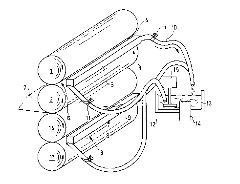
Fig. 1 shows a nip guard incorporated into a closed circ~ ting system of
a m.odillm;
Fig. 2 shows electrical resistance elçm~ntc being integrated in a guard;
Fig. 3 shows an embodiment having alternating current generator;
Fig. 4 is an embodiment having a crossbar and side frames integrated in
a circulation loop of a m~ lm;
Fig. S shows a dalllpening system having pans which are connected to a
circ~ ting fluid piping system; and
Fig. 6 is an embodiment having a blanket washing device with electrical
heating elements.
Detailed Description of the Invention
Fig. 1 shows an upper cylindrical body 1 and lower cylindrical body 2 of a
~lhl~ g unit. Between two first upper and lower printing unit cylinders 1, 2 andtwo second upper and lower printing unit cylinders 16, 17 a web of material 7 is2S printed on both sides thereof. A nip guard 3 protecting the press operator from
being injured has surfaces indicated by 4 and 5. The nip guard 3 is connected toa pipe system 8 having a supply portion 9 as well as a recirculation portion 10,both of which are coMected to a reservoir 12. Within the reservoir 12 a medium
13 is kept at a constant temperature level. The m.o~ m 13 within the reservoir
12 -- such as water, oil, air or a mixture of other components -- is stirred by a
pumping device 15,thereby gener~ling a uniform temperature distribution in the
m~ lm 13 within the reservoir 12. In the event that the temperature level of the
1 649/49
84226 4

~1 7~1 b7
mloAium 13 being recirculated through the reservoir 12 via the recirculation
portion 10 of the pipe system 8 has changed .cignificqntly, the te,l,peld~ulc of the
m~dillm 13 can be controlled via a heat exchanger 14 aSsign~A to the reservoir 12.
The pipe system 8 includes flow control devices 11 to adjust the flow of heatingS m~Aillm 13 to the colllpol~nl 3.
In the embodiment shown in Fig. 1 the component is a nip guard 3 having
a hollow interior. But into a closed loop of similar configuration other
compol~ell~, such as shields, crossbars, frames, etc. of a ~ ing unit can be
integrated to prevent conA~nsqtion drops being formed thereon which spoil the
print quality.
Fig. 2 shows electrical lesi~dllce elements being integrated into a guard.
In this embodiment a nip guard 3 is assigned to the nip 6 between the first upper
and lower printing unit cylinders 1, 2 and the second upper and lower printing
cylinders 16, 17"~ eclively. Each of said nip guards 3 has electrical ~ e
eleme~ts 28 being conne~;ted via wires 19 to a power source 18, or can include asingle resictqnne element which extends along the length of the nip guard 3.
Thus, the ~c"lpeldture of the nip guard 3 is mqintqin.o~A above the ambient dew
point, preventing conAencqtion. In addition to nip guard 3 as shown in Fig. 2,
shields, frame parts, tail tuckers and the like can be equipped with the elecllical
resistance elern~T-tc. 28 connected to a power source 18.
Fig. 3 illustrates an alternative embodiment using an allell~ling current
generator. In this embodiment nip guards 3 having induction coils 21 are q-csign~A
to each of the nips 6 ~~ en the cylinder surfaces 1, 2 and 16, 17, lc~cli~/ely.
The induction coils 21 are conn~cte~ via wires 19 to an alternating current
generator 20. The altel"aling current flowing in the induction coils 21 induces
eddy-currents in the nip guards 3 or other components where condensation is
likely to occur, to alter the temperature difference between said components'
surfaces and the surrounding air.
Fig. 4 shows a clossl,ar being integrated into the circulation loop of the
medium 13. Instead of nip guard 3 as disclosed in the embodiment of the
invention according to Fig. 1, a crossbar 3 or even the side frames 22, 23 can be
integrated into the pipe system 8 circnlq-ting the mtodinm 13.
I 649/49
84226 5

21 741 6~
Fig. 5 shows an embo~lim~nt having a ~ ing system being integrated
into a circulation loop. The dampening system 24 comprises an outer pan 25 and
an irmer pan 26. The outer pan 25 is integrated into the pipe system 8 allowing
the mPdillrn 13 to flow through the outer pan 25, thus m~int~ining its telllpel~lu~e
above the dew point.
A further embodiment, illustrated in Fig. 6, shows a blanket washing device
27 which is equipped with electrical resi~t~nce elements 28 connected to a powersource 18 via wires 19. The power loss in the re~ict~nre elements 28 heats the
blanket washing device 27 thus m~int~ining its surface temperature above the dew point, to prevent condensation.
1649/49
84226 6

Dessin représentatif
Une figure unique qui représente un dessin illustrant l'invention.
États administratifs

2024-08-01 : Dans le cadre de la transition vers les Brevets de nouvelle génération (BNG), la base de données sur les brevets canadiens (BDBC) contient désormais un Historique d'événement plus détaillé, qui reproduit le Journal des événements de notre nouvelle solution interne.

Veuillez noter que les événements débutant par « Inactive : » se réfèrent à des événements qui ne sont plus utilisés dans notre nouvelle solution interne.

Pour une meilleure compréhension de l'état de la demande ou brevet qui figure sur cette page, la rubrique Mise en garde , et les descriptions de Brevet , Historique d'événement , Taxes périodiques et Historique des paiements devraient être consultées.

Historique d'événement

Description Date
Le délai pour l'annulation est expiré 2013-04-15
Lettre envoyée 2012-04-16
Inactive : CIB de MCD 2006-03-12
Lettre envoyée 2005-02-11
Accordé par délivrance 2000-02-29
Inactive : Page couverture publiée 2000-02-28
Inactive : Renseign. sur l'état - Complets dès date d'ent. journ. 1999-11-22
Inactive : Dem. traitée sur TS dès date d'ent. journal 1999-11-22
Préoctroi 1999-11-08
Inactive : Taxe finale reçue 1999-11-08
Un avis d'acceptation est envoyé 1999-07-19
Lettre envoyée 1999-07-19
Un avis d'acceptation est envoyé 1999-07-19
Inactive : Approuvée aux fins d'acceptation (AFA) 1999-07-05
Demande publiée (accessible au public) 1996-10-26
Toutes les exigences pour l'examen - jugée conforme 1996-04-15
Exigences pour une requête d'examen - jugée conforme 1996-04-15

Historique d'abandonnement

Il n'y a pas d'historique d'abandonnement

Taxes périodiques

Le dernier paiement a été reçu le 1999-04-09

Avis : Si le paiement en totalité n'a pas été reçu au plus tard à la date indiquée, une taxe supplémentaire peut être imposée, soit une des taxes suivantes :

  • taxe de rétablissement ;
  • taxe pour paiement en souffrance ; ou
  • taxe additionnelle pour le renversement d'une péremption réputée.

Les taxes sur les brevets sont ajustées au 1er janvier de chaque année. Les montants ci-dessus sont les montants actuels s'ils sont reçus au plus tard le 31 décembre de l'année en cours.
Veuillez vous référer à la page web des taxes sur les brevets de l'OPIC pour voir tous les montants actuels des taxes.

Historique des taxes

Type de taxes Anniversaire Échéance Date payée
TM (demande, 2e anniv.) - générale 02 1998-04-15 1998-04-02
TM (demande, 3e anniv.) - générale 03 1999-04-15 1999-04-09
Taxe finale - générale 1999-11-08
TM (brevet, 4e anniv.) - générale 2000-04-17 2000-04-03
TM (brevet, 5e anniv.) - générale 2001-04-16 2001-03-29
TM (brevet, 6e anniv.) - générale 2002-04-15 2002-03-27
TM (brevet, 7e anniv.) - générale 2003-04-15 2003-03-27
TM (brevet, 8e anniv.) - générale 2004-04-15 2004-03-26
Enregistrement d'un document 2005-01-24
TM (brevet, 9e anniv.) - générale 2005-04-15 2005-03-21
TM (brevet, 10e anniv.) - générale 2006-04-17 2006-03-17
TM (brevet, 11e anniv.) - générale 2007-04-16 2007-03-19
TM (brevet, 12e anniv.) - générale 2008-04-15 2008-03-17
TM (brevet, 13e anniv.) - générale 2009-04-15 2009-03-18
TM (brevet, 14e anniv.) - générale 2010-04-15 2010-03-18
TM (brevet, 15e anniv.) - générale 2011-04-15 2011-03-17
Titulaires au dossier

Les titulaires actuels et antérieures au dossier sont affichés en ordre alphabétique.

Titulaires actuels au dossier
HEIDELBERG WEB SYSTEMS, INC.
Titulaires antérieures au dossier
DREW E. KIEFABER
JEFFREY R. RUMMLER
Les propriétaires antérieurs qui ne figurent pas dans la liste des « Propriétaires au dossier » apparaîtront dans d'autres documents au dossier.
Documents

Pour visionner les fichiers sélectionnés, entrer le code reCAPTCHA :


Pour visualiser une image, cliquer sur un lien dans la colonne description du document. Pour télécharger l'image (les images), cliquer l'une ou plusieurs cases à cocher dans la première colonne et ensuite cliquer sur le bouton "Télécharger sélection en format PDF (archive Zip)" ou le bouton "Télécharger sélection (en un fichier PDF fusionné)".

Liste des documents de brevet publiés et non publiés sur la BDBC .

Si vous avez des difficultés à accéder au contenu, veuillez communiquer avec le Centre de services à la clientèle au 1-866-997-1936, ou envoyer un courriel au Centre de service à la clientèle de l'OPIC.


Description du
Document 
Date
(aaaa-mm-jj) 
Nombre de pages   Taille de l'image (Ko) 
Dessin représentatif 2000-01-30 1 16
Dessin représentatif 1998-03-30 1 19
Abrégé 1996-07-17 1 11
Description 1996-07-17 6 243
Revendications 1996-07-17 3 63
Dessins 1996-07-17 6 77
Rappel de taxe de maintien due 1997-12-15 1 111
Avis du commissaire - Demande jugée acceptable 1999-07-18 1 165
Avis concernant la taxe de maintien 2012-05-27 1 172
Correspondance 1999-11-07 1 35
Correspondance de la poursuite 1999-05-18 2 76
Demande de l'examinateur 1998-11-18 2 58