Note : Les descriptions sont présentées dans la langue officielle dans laquelle elles ont été soumises.
CA 02174242 1999-09-10
METHOD AND SYSTEM FOR PROCESSING FIRST AND SECOND
DIGITAL SIGNAL VERSIONS OF A SIGNAL IN A DIVERSITY RECEIVER
Field of the Invention
The present invention relates generally to communications
systems and more particularly to a system for diversity reception
of a signal.
Background of the Invention
In a wireless communication environment in which one of
the communication units is mobile, the reception of RF (radio
frequency) signals often requires the use of diversity techniques to
combat the effects of Raleigh fading. Various diversity reception
methods have been used to reduce the effect of this fading,
including such techniques as switching among antennas prior to
discrimination, selection among several receivers, and combining
2 0 signals from several receivers (e.g., max-ratio combining).
However, there are drawbacks to these approaches. The use of
pre-discrimination antenna switching in analog systems leads to
phase discontinuities when the antennas are switched. This in turn
results in "pops" in the recovered audio signal, which is
2 5 unacceptable to most users. This result is even less tolerable in a
digital receiver because it leads to unacceptable loss of information
(voice and data). Diversity combining approaches like max-ratio
combining may lead to acceptable quality, and often better quality
than selection diversity techniques, but these come at the expense
3 0 of a much more computationally intensive implementation. This
typically means more expensive circuitry and higher power
consumption, both of which are undesirable in mobile
communications.
CA 02174242 1999-09-10
-2-
Selection diversity receivers require less circuitry or
computations than diversity combining receivers, but prior art
selection diversity approaches still typically rely on separate signal
paths, each including all the necessary receiver circuitry from the
demodulator forward to the antenna. FIG. 1 illustrates such a prior
art diversity receiver. Receiver 110 receives spatially diverse
versions of the same signal at antennas 112, 114, 116. These
signal versions are processed along different signal paths or
branches via RF (radio frequency) front ends 122, 124, 126 and
demodulators 142, 144, 146. The received signal strengths (RSSI)
of the signal versions on each branch are determined in RSSI
detectors 132, 134, 136, and the branch having the greatest RSSI is
selected via diversity switch 150 using the RSSI information.
The problem with such a prior art selection diversity
receiver is that it requires duplicate circuitry and signal processing
constantly running in parallel for each signal path, up through and
including demodulation. Only after the separate signal paths have
been demodulated is a decision (selection) made about which
signal to use for the output. This additional circuitry and
2 0 computational demand ultimately leads to a more expensive
receiver and higher power consumption.
Accordingly, there exists a need for a diversity receiver
reducing circuitry and computational requirements, but while still
performing diversity reception of high speed signals at an
2 S acceptable quality and substantially reducing the effects of fading.
Summary of The Invention
In order to address this need and others, the present invention
provides a method of processing first and second digital signal versions of a
signal
3 0 in a diversity receiver. The method includes the steps of processing the
first and
second digital signal versions by decimating one of the first and second
digital signal
CA 02174242 1999-09-10
- 2A -
versions to produce a decimated signal, and filtering the other of the first
and second
digital signal versions to produce a filtered signal. The filtered signal has
a first
sampling frequency and the decimated signal has a second sampling frequency.
The
first sampling frequency exceeds the second sampling frequency. The method
further includes the steps of determining a signal quality of the decimated
signal and
a signal quality of the filtered signal, and outputting the filtered signal
when the
signal quality of the filtered signal is greater than the signal quality of
the decimated
signal.
According to another aspect of the present invention, a receiver for providing
diversity reception that has at least first and second branches for receiving
at least
first and second signal versions of a signal is provided. The receiver
includes a first
and second digital downconverter on the first and second branches, a first and
second filter/decimator responsive to the first and second downconverter, a
first and
second signal quality detector responsive to the first and second
filter/decimator, and
a diversity selector responsive to the first and second signal quality
detector. The
first and second digital downcoverters are on the first and second branches,
respectively. The first and second digital downcoverters digitize and
downconvert
the first and second signal versions and output first and second digital
signal
versions, respectively. The first and second filter/decimators either decimate
or filter
the first and second digital signal versions. The first and second signal
quality
detectors determine the signal quality of the first and second digital signal
versions,
respectively. The diversity selector determines which of the fist and second
digital
signal versions has greater signal quality. When the first digital signal
version has
greater signal quality, the diversity selector controls the first
filter/decimator to filter
the first digital signal version and output a filtered digital signal to a
demodulator
and controls the second filter/decimator to decimate the second digital signal
version
and output a decimated digital signal to the demodulator. The first filtered
digital
signal has a sampling frequency greater than the sampling frequency of the
decimated signal.
r CA 02174242 1999-09-10
- 2B -
In accordance with a further aspect of the present invention, the receiver
comprises first and second filter and decimator devices coupled to first and
second
branches, respectively, a diversity switch controller responsive to the first
and
second filter and decimator devices, and a demodulator responsive to the
diversity
switch controller and the first and second filters. The demodulator comprises
a
phase detector responsive to the first and second filter and decimator
devices. The
phase detector determines phase information based on a filtered signal
produced by
the first filter and decimator device and a decimated signal produced by the
second
filter and decimator device.
Brief Description of the Drawings
FIG 1 is a block diagram illustrating a prior art selection diversity
receiver.
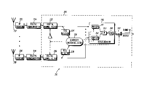
FIG 2 is a block diagram of a diversity receiver according to a preferred
embodiment of the invention.
25
WO 96/07247 PCT/US95/09129
-3-
FIG. 3 is a graph illustrating signal information outputted
from filters 232 and 236 of the diversity receiver of FIG. 2.
FIG. 4 is a graph illustrating phase discontinuity that may
occur when switching between signal paths in an analog system
prior to demodulation.
FIG. 5 is a graph illustrating how phase discontinuity may be
avoided using the diversity receiver of FIG. 2.
FIG. 6 is a flow chart illustrating the steps for selecting a
signal path using the diversity receiver of FIG. 2.
Detailed Description of the Preferred Embodiment
These problems and others are met with a method and
apparatus for diversity selection according to the present
invention. Fig. 2 shows a block diagram of a presently preferred
embodiment of the invention. In this embodiment the receiver
210 uses digital techniques to allow selection diversity with a
single demodulator or discriminator 240 (for FM (frequency
modulated) demodulation), but without introducing any phase
discontinuity when switching between the branches starting with
2 0 antennas 212, 216. While this embodiment illustrates the
preferred implementation of a receiver for FM cellular or trunked
radio communications, it should be understood that the invention
also has application to other modulation schemes, including but not
limited to DPSK (differential phase shift key), and with any type of
2 5 wireless access communication system. The following description
of this presently preferred embpdiment is thus intended for
illustration and not a limitation on the scope of the invention.
When the signal versions are received on the different
branches via antennas 212, 216, they are processed and digitized
3 0 via RF front ends 222, 226 and digital downconverters 224, 228,
respectively. The digitized signals are then fed into filters 232,
WO 96!07247 PCT/US95/09129 ~j
~1~ ~~4~
-4-
236 and either decimated or filtered, depending upon which
branch has been selected as the active branch. Thus, for example, ,
where the first branch is the active branch, filter 232 will act to
filter (i.e., produce all the samples necessary for baseband signal ,
recovery) the digitized signal version on the first branch. This
filtered signal is then inputted to discriminator 240, via buffer
241, and demodulated via phase detector 243 and differentiator
245. The second branch, on the other hand, outputs a decimated
sample from filter 236, which has been controlled to operate as a
decimator. The decimated sample is inputted to buffer 242, but is
discarded as long as the second branch remains inactive.
Fig. 3 illustrates a typical output for the first arid second
branches following filters 232, 236. While the first branch (branch
1 in Fig. 3) remains active, a continuous stream of samples, i.e. the
filtered signal, in branch 1 is outputted to both RSSI detector 234
and buffer 241 of discriminator 240. Branch 2, on the other hand,
is inactive so only periodic decimated samples are inputted to RSSI
238 and buffer 242 of discriminator 240. At the end of a
predetermined number, or batch, of samples, the sample (e.g., 306)
2 0 on the inactive branch and the corresponding sample (e.g., 308) on
the active branch are used to determine the branch having the
greatest signal quality. One skilled in the art will appreciate that
there are a variety of ways in which the signal information may be
used to determine relative signal quality, and that the batch sizes
2 S and number of samples considered will vary depending upon the
specific circuitry design choices employed. In the case of the
embodiment of FIG. 2, both the current samples 306, 308 and a
predetermined number of prior samples 302, 304 at the end of
prior batches are averaged for each branch and then compared.
3 0 In order to determine, when to switch between branches,
signal quality information from both branches is compared in
diversity switch/selector 250. In the preferred embodiment this '
is accomplished by measuring the signal strength of the filtered
and decimated signals on the active and inactive branches,
WO 96/07247 PCT/US95/09129
respectively, via RSSI detectors 234, 238. One skilled in the art
will appreciate that other forms of signal quality measurement
may be employed other than RSSI, and that measurement could be
made earlier in the branches (e.g., following digital
downconverters 224, 228) in an appropriately configured receiver.
The detected signal information is then compared at diversity
selector 250 to determine which branch has the highest quality
signal. Diversity selector 250 controls filters 232, 236 and buffers
241, 242 to output appropriate information depending upon which
branch is selected as the active branch--the branch with the
highest quality signal. In other words, while the first branch
remains the active branch, diversity selector 250 will output a
first control signal to filter 232 via inverter 230 controlling filter
232 to remain in filter mode; at the same time the first control
signal will control filter 236 to remain in decimation mode.
Further control signals will control: buffer 241 to output signal
information to phase detector 243; buffer 242 to discard the
stored samples; and switch 247 to discard the output of
differentiator 245 during a transition between branches.
2 0 Thus, when it is determined that the inactive branch now
has a higher signal quality, diversity selector 250 functions to
switch the modes of filters 232 and 236, causing filter 232 to
decimate further signal inputs, and filter 236 to continuously filter
the signal on the second branch. At the same time, diversity
2 5 selector 250 sends a control signal to buffer 242 to output the last
decimated sample to phase detector 243 for purposes of providing
initial phase history for the now active second branch. Switch 247
is controlled to discard, or send to a dummy output, the
differentiator output, which is the difference between the phase
3 0 information of the Iast sample 309 of the first branch and the
phase information of decimated sample 310 of the second branch.
Switch 247 then reconnects the output of differentiator 245 so as
to output the differentiated signal information of the now active
second branch.
WO 96/07247 PCT/US95/09129
-6-
This approach is particularly advantageous in that the last
decimated sample 310 serves as an initial phase history for the
differentiator 245, something which could not be accomplished
with prior art techniques without employing duplicate
discriminators for each branch. FIGS. 4 and 5 further illustrate
how phase discontinuity is eliminated using phase history and the
present invention. FIG. 4 illustrates the effect of switching if only
one discriminator were used in a prior art analog implementation,
without consideration of some form of phase history information
for the inactive branch when switching it active. The numbered
vectors in FIG. 4 represent the phase angles at successive sample
instants for each of the two antennas 212, 216 (denoted as A and
B for the respective first and second branches). Assuming that
antenna 212 has been selected for the first branch (branch A), at
sample instant 2 an RSSI calculation leads to a determination that
the signal quality on the second branch is now stronger than on
the first branch, so the second branch (branch B) will be used at
sample instant 3. Thus, at sample instant 2 a phase difference ~~ 1
has been calculated by differentiator 245 based on current sample
2 0 2A of the active branch and prior sample lA. However, because
the second branch is being switched in as the active branch, under
prior art techniques at sample instant 3 a phase difference A~2
would be calculated using samples 2A and 3B. As can be seen, a
large discontinuity will occur between samples 2 and 3 since these
2 5 come from different signal paths. Such a large discontinuity will
most likely result in undesirable outputs such as "popping" or lost
data.
FIG. 5 illustrates how this effect is eliminated using the
digital selection diversity technique according to the present
3 0 invention. In this case, when branch B is switched to the active
branch on sample 3, the discriminator 245 will have already
-precomputed previous sample 2B on the second branch. This ,
sample is used to compute the difference between samples 2B and
3B so that no phase discontinuity will be experienced at the output
WO 96/07247 PCT/ITS95/09129
_ 7 _
of discriminator 240. The difference, if any is calculated, between
sample 2A and 3B is discarded on a dummy output.
FIG. 6 illustrates a flow chart for a presently preferred
method of implementing the invention. Steps 410-418 show the
steps by which, the signal information is processed when there is
no change in a then current active branch. When a determination
has been made that the RSSI of the inactive branch is now greater
than the RSSI of the active branch (step 416), the modes of filters
232, 236 are switched and a pointer is provided to discriminator
240 for the last decimated output of the previously inactive
branch. Thus, the necessary phase history for switching the
inactive branch into an active branch is provided (steps 420-424).
In the present embodiment, it has been assumed that simple
differences are used to compute the output of discriminator 245.
It is also possible to use more than two samples to obtain a more
accurate estimate for the derivative of the phase, using circuitry
like a multitap differentiator. However, buffers should still be
maintained which contain a sufficient number of samples for each
antenna, so that the derivative of the phase may be computed
2 0 without loss of continuity or initial phase history each time a new
branch is selected. In a software implementation, for example
when diversity selector 250 and discriminator 240 are
implemented in a digital signal processor (DSP) 260, this scheme
merely requires modification of an input pointer passed to a single
2 5 discriminator/demodulator routine when antenna paths are
switched so that the correct sample history is used to compute the
phase of the newly selected branch. In this manner, it is only
necessary to discriminate the active branch so that a savings in
processor bandwidth may be realized. The scheme is also
3 0 advantageous in a digital hardware implementation since it is only
necessary to build a single discriminator regardless of the number
of receive antennas used.
There has thus been shown a digital selection diversity
receiver eliminating the need for duplicate demodulators along the
WO 96/07247 PCT/US95/09129 i,
~~°~4~4~
_g_
plural signal paths, and saving circuitry and/or computational
capacity. While the invention has been described with reference
to an illustrative embodiment thereof, it will be apparent to one
skilled in the art that various modifications and changes can be ,
made without departing from the spirit and the scope of the
invention. For example, a skilled artisan will appreciate that
although the digital receiver circuitry has been logically separated
in the detailed description above, the actual implementation of
these functions may be accomplished in a variety of different
manners including, but not limited to, properly programming a
DSP, coupling discrete components together, and using a
combination of one or more application specific integrated circuits
(ASICs). ~ Nor is the invention limited to FM or cellular systems, as
it may have application to any wireless access system in which at
least one communication unit is capable of movement. Rather, the
spirit and scope of the invention should be understood in view of
the claims below.