Sélection de la langue

Search

Sommaire du brevet 2174696 

Énoncé de désistement de responsabilité concernant l'information provenant de tiers

Une partie des informations de ce site Web a été fournie par des sources externes. Le gouvernement du Canada n'assume aucune responsabilité concernant la précision, l'actualité ou la fiabilité des informations fournies par les sources externes. Les utilisateurs qui désirent employer cette information devraient consulter directement la source des informations. Le contenu fourni par les sources externes n'est pas assujetti aux exigences sur les langues officielles, la protection des renseignements personnels et l'accessibilité.

Disponibilité de l'Abrégé et des Revendications

L'apparition de différences dans le texte et l'image des Revendications et de l'Abrégé dépend du moment auquel le document est publié. Les textes des Revendications et de l'Abrégé sont affichés :

  • lorsque la demande peut être examinée par le public;
  • lorsque le brevet est émis (délivrance).
(12) Demande de brevet: (11) CA 2174696
(54) Titre français: RAQUETTE DE SPORT
(54) Titre anglais: SPORTS RACKET
Statut: Réputée abandonnée et au-delà du délai pour le rétablissement - en attente de la réponse à l’avis de communication rejetée
Données bibliographiques
Abrégés

Abrégé français

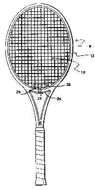
Cette invention concerne une amélioration apportée à une raquette de sport à coeur bibranche et cadre à pont fendu, ledit cadre comportant des tunnels de cordage pour faire passer les cordes qui forment la surface de frappe, le manche ayant un coeur en Y dont les deux branches définissent entre leur point de jonction avec le cadre un pont qui présente en son milieu une solution de continuité. Les extrémités libres du pont s'articulent sur un insert ayant pour rôle d'atténuer les chocs ressentis au bras du joueur. L'amélioration provient de la longueur accrue du pont qui peut comporter au moins quatre tunnels de cordage dans l'axe des cordes longitudinales correspondantes, pont entre les extrémités libres duquel est montée une cheville servant à limiter le déplacement relatif desdits extrémités et à prévenir la fissuration du cadre.


Abrégé anglais


This invention relates to an improvement in a split bridge
sports racket having a frame with a rim and a handle, the rim
being formed with string tunnels through which the string extends
to form an impact surface, the handle having a Y configuration,
the arms of which merge with the rim to define a bridge section
of the rim that extends between the ends of the arms of the Y
configuration, the bridge having a discontinuity, the free ends
of the bridge at the discontinuity articulating with a bridge
insert to reduce player arm stress in use. The improvement
resides in providing a bridge having a length to accommodate at
least four central longitudinal string tunnels of the racket with
each central longitudinal string tunnel extending in the same
direction as their respective longitudinal strings through the
said bridge and wherein a support plug is mounted within the
hollow of each of the free ends of the bridge to limit the
movement of the free ends during play and prevent cracking of the
frame from use.

Revendications

Note : Les revendications sont présentées dans la langue officielle dans laquelle elles ont été soumises.


The embodiments of the invention in which an exclusive property
or privilege is claimed are defined as follows:
1. In a split bridge sports racket having a hollow frame
with a rim and a handle, the rim being formed with string tunnels
through which the string extends to form an impact surface, the
handle having a Y configuration, the arms of which merge with the
rim to define a bridge section of the rim that extends between
the ends of the arms of the Y configuration, the bridge having a
discontinuity, the free ends of the bridge at the discontinuity
articulating with a bridge insert to reduce player arm stress in
use, the improvement of a bridge having a length to accommodate
at least four central longitudinal string tunnels of the racket;
each of said central longitudinal string tunnels extending in the
same direction as its respective longitudinal string through the
said bridge; and wherein a support plug is mounted within the
hollow of each of the free ends of the bridge to limit the
movement of the free ends during play and prevent cracking of the
frame from use.
2. In a split bridge sports racket having a hollow frame
with rim and a handle, the rim being formed with string tunnels
through which the string extends to form an impact surface, the
handle having a Y configuration, the arms of which merge with the
rim to define a bridge section of the rim that extends between

the ends of the arms of the Y configuration, the bridge having a
discontinuity, the free ends of the bridge at the discontinuity
articulating with bridge insert to reduce player arm stress in
use, the improvement as claimed in Claim 1 wherein:
there is provided a strip member to underlie the bridge of
the racket, said strip member being of a length to accommodate
the string passing through it at least four times.
3. In a split bridge sports racket having a hollow frame
with a rim and a handle, the rim being formed with string tunnels
through which the string extends to form an impact surface, the
handle having a Y configuration, the arms of which merge with the
rim to define a bridge section of the rim that extends between
the ends of the arms of the Y configuration, the bridge having a
discontinuity, the free ends of the bridge at the discontinuity
articulating with a bridge insert to reduce player arm stress in
use, the improvement as claimed in Claim 1 wherein the bridge has
a length to accommodate at least six central longitudinal string
tunnels of the racket; the said central longitudinal string
tunnel extending in the same direction as their respective
longitudinal strings through the said bridge.

Description

Note : Les descriptions sont présentées dans la langue officielle dans laquelle elles ont été soumises.


~174696
,.
This application relates to a sports racket of the type used
in a game such as te~ni~, racket ball or squash, and having a
split-frame.
Split-frame rackets of the type having a discontinuous rim
plugged with a resilient insert are not new. They were developed
to increase the size of the sweet spot on the stringed face of
the racket and to lessen the impact transferred through the
racket from the ball to the arm of the player. The split frame
and resilient insert allowed the rim of the racket head to flex
more than it would otherwise and absorb some of the impact that
would have otherwise been felt by the player's arm into the
racket head. The split frame represents an advance in the art of
racket sports for those reasons.
An example of a split-frame racket is as taught in the
inventor's prior U.S. patent 5,350,173.
Split frame rackets are pressure-moulded and, as well, they
are hollow because of weight considerations.
In the design of split-frame rackets, it is acknowledged
that the split bridge of the racket is less structurally strong
than the continuous bridge of a conventional racket and that
compensation for this difference has to be made in the design of
the racket. Otherwise, the repeated impact of a high velocity

~ - 217~696
ball, during play, would cause breakage of the racket. It is for
this reason that all split-frame rackets made to date have been
made by splitting the rim at its central bridge area and
designing the string arrangement so that no more than two string
tunnels go directly through the bridge, with the adjacent string
tunnels being directed to the side of the racket head. If the
strings are not directed to the side, the free ends of the racket
rim would move too much during play.
However, it has become apparent over time that the split-
frame racket, for all of its advantages, does have a serious
drawback. The stress caused by the impact which has been re-
directed from the player's arm back to the racket has caused a
higher incidence of string breakage. The stress has been
successfully re-directed, but too much of that re-directed stress
has then been borne by the strings. For instance, it would not
be uncommon for a person of professional calibre to have to re-
string their split-frame racket after only about two hours of
play because of string breakage. Using a non-split frame, the
same player would only have to re-string after about eight hours
of play.
As long as the split-frame racket has been available, which
has been a substantial number of years, this problem has
persisted. The present invention, however, provides a
satisfactory solution.

~ . ~17469~
It i8 an object of the present invention to provide a string
racket with a split frame that lessens the problem of string
breakage, while still maintAining the advantages of a split-frame
racket.
According to an aspect of the present invention, there is
provided in a split bridge sports racket having a hollow frame
with a rim and a handle, the rim being formed with string tunnels
through which the string extends to form an impact surface, the
handle having a Y configuration, the arms of which merge with the
rim to define a bridge section of the rim that extends between
the ends of the arms of the Y configuration, the bridge having a
discontinuity, the free ends of the bridge at the discontinuity
articulating with a bridge insert to reduce player arm stress in
use, the improvement of a bridge having a length to accommodate
at least four central longitudinal string tunnels of the racket;
each of said central longitudinal string tunnels extending in the
same direction as its respective longitudinal string through the
said bridge; and wherein a support plug is mounted within the
hollow of each of the free ends of the bridge to limit movement
of the free ends of the bridge during play and prevent cracking
of the frame from use.
The invention will be more clearly understood after
reference to the following specification given in conjunction

217~696
with the drawings in which:
FIGURE 1 is an illustration of a front view of the preferred
embodiment of the present invention;
FIGURE 2 i8 an illustration of a partial perspective view of
the preferred embodiment of the invention;
FIGURE 3 is an illustration showing the parts used in the
manufacture of the preferred embodiment;
FIGURE 4 is an illustration of a racket having a split frame
of the type that has been used prior to this invention, with the
stringing extending through the bridge portion illustrated in
phantom.
Referring to the embodiment illustrated in Figures 1 to 3,
there is shown a racket generally referred to by the numeral 8,
strung under pressure with strings generally indicated by the
numeral 10 of the conventional type. The racket frame has a Y-
shaped handle 12 and a head with a rim 13 that has a
discontinuity at its bridge portion to provide two spaced free
ends 17.
Within the hollow of each of the free ends of the bridge,
there i8 mounted a support plug 19. Each support plug 19 limits

2~74~9S
the misshaping of its free end during play. Without this
feature, the problem of the prior art, namely the cracking of the
frame, would persist.
The embodiment of an old style split-frame racket, of the
type available, and illustrated in Figure 4, with its comparable
parts similarly numbered.
The difference between the embodiment of Figure 4 and the
embodiment of Figures 1 to 3 are twofold. Firstly, there are
only two longitudinal string tunnels 15 extending the same
direction as their respective longitudinal string lengths,
numbered lOa and lOb, through the free ends 17 at the bridge in
the Figure 4 embodiment. Secondly, there are no support plugs 19
in the Figure 4 embodiment. But in the embodiment shown in
figures 1 to 3, there are six string tunnels 16 extending in the
same direction as their respective longitudinal string lengths
through the free ends 17 at the bridge. And there are support
plugs 19.
In Figure 4, it would not be possible to direct more than
two longitudinally-extending string tunnels through the bridge
because such redirection would eventually lead to breakage of the
bridge as described above. The string tunnels 15 are therefore
directed to the side, as shown in phantom.

217469S
In the racket of this invention, by redirecting the
stringing, it has been found that the stress exerted on the
strings 10 on impact is reduced because there is less redirection
and less breakage of the strings 10 occur. However, the
advantages of a bigger sweet spot and reduction of the impact
transferred to the player's arm remain. Also, with the support
plugs 19, the racket frame remains strong enough and a better
playing racket without significant risk of bridge breakage.
The insert, generally referred to by the numeral 20, is
transversely sloped at surfaces 22 which are designed to permit
the ends 17 to bend laterally of the plane of the rim of the
racket head upon impact of a ball during play. A significant
modification now possible with the current invention is the
lengthening of the strip member 25, further spreading the stress
resulting from the impact of the ball during play. In the prior
art, as illustrated in Figure 4, the strip member 25 is of a more
limited length, not providing the same spreadout of stress.
The lower outer strip member 24, as is the case in both the
prior art and the preferred embodiment of this invention, is
formed with sheaths 26 that extend from the strip member and
secure the insert 20 in the racket.
The stringing of the racket, shown in the preferred
embodiment, is conventional. The strip member 24 is held in

~ 21 7 4 6 9 ~
place in the racket by the tension of the string lengths lOa,
lOb, lOc, lOd, lOe and lOf of string 10 which extends through and
around the rim and is continuous.
Mounted around the free ends of sheaths 30 is a shock
absorbing clamp member 32. The clamping member 32 overlaps the
strings of the racket and the free ends of the sheaths 30 to
transfer, during play, vibrations for the impact of a ball
through the sheaths 26 and strip member 24 to the insert 20.
The insert 20 (but not the lengthen;ng of strip member 25),
the clamping member 32 and the strip member 24 with sheaths 26
are all components of the prior art.
The support plug in the preferred embodiment is made from
wood, but other suitable materials will be apparent. For
instance, a plastics material having the desired physical
characteristics could also be used. The purpose of the insert is
to provide the support necessary to restrict movement of the
inner free ends 17 enough to prevent cracking. The most
preferable materials are therefore those which have both the
necessary structural strength and are relatively light in weight.
In result of the modifications made in the direction of the
string tunnels and the restructuring of the bridge area of the
racket, there is less string breakage while still maintAin;ng the

~ 2~74~i9S
advantages of a split-frame racket.
It will be apparent to those skilled in the art that
modifications to the preferred embodiment illustrated above will
be possible without deviating from the substance of the invention
as claimed in the appended claims. It is not intended that the
description of the invention provided in this specification be
read in a limiting sense. The illustrated design is a preferred
one but is given by way of example only and not with the
intention that it define the limits of the application of the
principles of the invention to other designs.

Dessin représentatif
Une figure unique qui représente un dessin illustrant l'invention.
États administratifs

2024-08-01 : Dans le cadre de la transition vers les Brevets de nouvelle génération (BNG), la base de données sur les brevets canadiens (BDBC) contient désormais un Historique d'événement plus détaillé, qui reproduit le Journal des événements de notre nouvelle solution interne.

Veuillez noter que les événements débutant par « Inactive : » se réfèrent à des événements qui ne sont plus utilisés dans notre nouvelle solution interne.

Pour une meilleure compréhension de l'état de la demande ou brevet qui figure sur cette page, la rubrique Mise en garde , et les descriptions de Brevet , Historique d'événement , Taxes périodiques et Historique des paiements devraient être consultées.

Historique d'événement

Description Date
Inactive : CIB désactivée 2015-03-14
Inactive : Symbole CIB 1re pos de SCB 2015-01-17
Inactive : CIB du SCB 2015-01-17
Inactive : CIB expirée 2015-01-01
Inactive : CIB enlevée 2014-11-05
Inactive : CIB de MCD 2006-03-12
Demande non rétablie avant l'échéance 2002-04-22
Le délai pour l'annulation est expiré 2002-04-22
Réputée abandonnée - omission de répondre à un avis sur les taxes pour le maintien en état 2001-04-23
Inactive : Page couverture publiée 2000-12-21
Lettre envoyée 1999-05-26
Demande publiée (accessible au public) 1997-10-23

Historique d'abandonnement

Date d'abandonnement Raison Date de rétablissement
2001-04-23

Taxes périodiques

Le dernier paiement a été reçu le 1999-04-22

Avis : Si le paiement en totalité n'a pas été reçu au plus tard à la date indiquée, une taxe supplémentaire peut être imposée, soit une des taxes suivantes :

  • taxe de rétablissement ;
  • taxe pour paiement en souffrance ; ou
  • taxe additionnelle pour le renversement d'une péremption réputée.

Les taxes sur les brevets sont ajustées au 1er janvier de chaque année. Les montants ci-dessus sont les montants actuels s'ils sont reçus au plus tard le 31 décembre de l'année en cours.
Veuillez vous référer à la page web des taxes sur les brevets de l'OPIC pour voir tous les montants actuels des taxes.

Historique des taxes

Type de taxes Anniversaire Échéance Date payée
TM (demande, 2e anniv.) - petite 02 1998-04-22 1998-04-22
TM (demande, 4e anniv.) - petite 04 2000-04-25 1999-04-22
TM (demande, 3e anniv.) - petite 03 1999-04-22 1999-04-22
Titulaires au dossier

Les titulaires actuels et antérieures au dossier sont affichés en ordre alphabétique.

Titulaires actuels au dossier
CHARLES DICERBO
Titulaires antérieures au dossier
S.O.
Les propriétaires antérieurs qui ne figurent pas dans la liste des « Propriétaires au dossier » apparaîtront dans d'autres documents au dossier.
Documents

Pour visionner les fichiers sélectionnés, entrer le code reCAPTCHA :


Pour visualiser une image, cliquer sur un lien dans la colonne description du document. Pour télécharger l'image (les images), cliquer l'une ou plusieurs cases à cocher dans la première colonne et ensuite cliquer sur le bouton "Télécharger sélection en format PDF (archive Zip)" ou le bouton "Télécharger sélection (en un fichier PDF fusionné)".

Liste des documents de brevet publiés et non publiés sur la BDBC .

Si vous avez des difficultés à accéder au contenu, veuillez communiquer avec le Centre de services à la clientèle au 1-866-997-1936, ou envoyer un courriel au Centre de service à la clientèle de l'OPIC.


Description du
Document 
Date
(aaaa-mm-jj) 
Nombre de pages   Taille de l'image (Ko) 
Description 1996-07-24 8 235
Abrégé 1996-07-24 1 27
Revendications 1996-07-24 2 64
Dessins 1996-07-24 4 88
Dessin représentatif 1997-11-25 1 11
Dessin représentatif 2000-11-30 1 11
Rappel de taxe de maintien due 1997-12-22 1 111
Courtoisie - Lettre d'abandon (taxe de maintien en état) 2001-05-21 1 182
Taxes 1998-04-21 2 75
Taxes 2000-04-24 1 24
Correspondance 1999-05-25 1 22
Taxes 1999-04-21 2 56