Note : Les descriptions sont présentées dans la langue officielle dans laquelle elles ont été soumises.
21 75030
-
Aircraft Instruments
Back~round of the Invention
This invention relates to aircraft instruments.
The invention is more particularly concerned with instruments for warning a pilot of an
aircraft when the pitch rate deviates from a desired value during the rotation phase of take-off.
During take-offroll, the pilot rotates the aircraft (that is, lifts the nose offthe runway)
when the aircraft's rotation speed, Vr, is reached. The climb attitude of an aircraft is typically
20 from the horizontal. Before the pilot can put the aircraft safely into this attitude, the
aircraft must have lifted sufficiently to ensure that its tail does not strike the ground. Wing lift
does not occur immediately that rotation takes place because of the time taken by air
circulation to build up around the wing. The tail strike angle for a typical large wide-bodied
airliner is about 10, or about 12 when the suspension of main wheel landing gear is
extended as a result of the weight ofthe aircraft being taken offthe landing gear during
rotation. With an extended version of the aircraft, these angles would be reduced to about 7
and 8 respectively. Tail strike can occur on the ground if the nose is raised too quickly before
the main landing gear has lifted offthe ground. Tail strike can also occur in the air if the nose
is raised too quickly before sufficient height has been reached. The pilot must, therefore,
ensure that he does not rotate the aircraft with too high a pitch rate, to avoid tail strike.
Although instruments have been proposed previously for providing information to the pilot
during the flare-up phase oftake-off, such as described in US3309923, no instrument has
previously been able to provide information warning of possible tail strike during the very
early phase of take-off.
The take-off procedure is particularly stressful for the pilot because the engines are
operating at full power and the plane is fully loaded with fuel. The pilot must monitor many
instruments as well as controlling the engines and aerodynamic surfaces of the aircraft.
21 75030
Brief Summary of the Present Invention
It is an object of the present invention to provide an aircraft instrument that can be
used to assist the pilot during the rotation phase of take-off.
According to the present invention there is provided an aircraft instrument including
means for providing a signal indicative of the rate of change of pitch angle of the aircraft,
means for determining when the rate of change of pitch angle departs from a safe value, and
display means for providing a warning display to the pilot when the rate of change of pitch
angle during the rotation phase of take-off departs from the safe value.
The instrument preferably includes means for receiving an input from a sensor
responsive to lifting of the aircraft nose wheel at the start of rotation. The instrument is
preferably arranged to provide a first warning display when the pitch rate is too high and a
di~el ellL warning display when the pitch rate is too low. The warning display may include a
representation of a symbol that moves vertically when the pitch rate departs from a safe value
and that remains stationary when the pitch rate is at a safe value. The instrument may include a
processor, comparator means, a reference source of maximum rate of change of pitch angle
and a reference source of miniml]m rate of change of pitch angle, the processor being arranged
to receive signals from a pitch angle sensor and to derive a signal indicative of rate of change
of pitch angle, the comparator means receiving outputs from the reference sources of
minimllm and maximum rate of change of pitch angle and the signal indicative of rate of
change of pitch angle, and the comparator means providing an output to initiate said warning
display when the signal indicative of rate of change of pitch angle exceeds the maximum rate
of change of pitch angle or falls below the minimllm rate of change of pitch angle. The
instrument may be arranged to m~int~in the display offuntil the aircraft nose wheel lifts offthe
ground. The instrument may be arranged to turn offthe display a predetermined time after the
main landing gear has lifted offthe ground or after the aircraft has reached a predetermined
- 21 75030
height above the ground. The instrument may be arranged to provide an audible warning when
the rate of change of pitch angle during the rotation phase of take-off departs from a safe
value. The display of the instrument is preferably arranged for mounting in the peripheral field
of view of the pilot. The instrument may also be arranged to provide a warning display during
descent if pitch angle of the aircraft exceeds a safe value, and to provide lateral guidance
information to the pilot.
A tail-strike warning instrument for an aircraft, in accordance with the presentinvention, will now be described, by way of example, with reference to the accompanying
drawings.
Brief Description of the Drawin~s
Figure 1 is a schematic illustration of an aircraft showing the installation
of the instrument and various sensors;
Figure 2 is a schematic diagram of the instrument;
Figures 3A to 3 C show di~eren~ display representations provided by the
instrument; and
Figures 4 to 7 show alternative formats of display representation.
- 2 1 75030
Detailed Description of the Preferred Embodiments
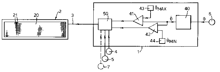
With reference first to Figures 1 and 2, the instrument includes an electronics housing
1 connected to a display unit 2 by a cable 3. The display unit 2 is mounted in the glareshield of
the aircraft flight deck so that it is in the peripheral field of view of the pilot; the housing 1
may be mounted anywhere in the aircraft or within the same unit as the display itself. The
instrument receives inputs from a nosegear squat switch 4 and from a main gear squat switch
5. These switches 4 and 5 provide outputs to indicate whether or not the nose gear or main
gear are on the ground. The instrument also receives an output ~ from a pitch angle sensor 6.
This sensor 6 may be contained within the electronics housing 1 or it could be a discrete
sensor located externally. Alternatively, the pitch angle sensing function could be provided by
an existing pitch angle sensor used for other purposes.
The electronics housing 1 includes a processor 40, which receives the output from the
pitch angle sensor 6 and, from this, derives an output ~ indicative of the rate of change of
pitch angle. Alternatively, pitch rate may be input directly from a pitch rate gyroscope sensor.
The processor 40 preferably also performs an averaging function to reduce the effect of pilot-
induced oscillations or other small perturbations in the pitch angle signal. The output from the
processor 40 is connected to one input of each of two comparators 41 and 42. Onecomparator 41 has its other input connected to a reference source 43, which sets a maximum
value of rate of change of pitch angle ~ . The other comparator 42 has its other input
connected to a reference source 44, which sets a minimllm value of rate of change of pitch
angle ~ ,. The outputs from the two comparators 41 and 42 are connected to a display driver
unit 50. The display driver unit 50 also receives the outputs from the nosegear squat switch 4
and from the main gear squat switch 5. The display driver unit 50 is connected to the display
unit 2 by the cable 3 and provides the output from the electronics housing 1.
- 2 1 75030
The display unit 2 is of rectangular shape and has a front surface or screen 20 occupied
by a matrix array of liquid crystal display elements 21, or some other electrically-energizable
display elements, such as LEDs.
When the aircraft starts its ground roll, both its nose and main gear are on the ground
and the sensors 4 and 5 supply signals indicating this to the instrument 1. During this part of
the take-off procedure, the instrument 1 holds the display unit 2 off so that the pilot is not
distracted.
When the pilot pulls back on the stick to raise the nose of the aircraft and start the
rotation phase of take-off, the nose gear starts to lift away from the ground and the nosegear
squat switch 4 changes its output. This causes the instrument 1 to energize the display unit 2.
While the pilot m~in~in.~ the pitch rate of the aircraft within safe limits, the display driver 50
produces a display representation on the screen 20 of the kind shown in Figure 3B. This
comprises a number of dark horizontal bars 22 (three bars are shown in Figure 3B) extending
across the display and separated by bright gaps 23. This display representation remains
stationary while the aircraft is m~int~ined within safe pitch rate lirnits, that is, less than ~3maX and
more than ~"il,. The pilot will see the display as it is turned on, in his peripheral field of view,
so that he is notified that the nose gear has lifted offthe runway. During rotation, the pilot
receives guidance from the display in his peripheral field of vision while looking forward out of
the cockpit windscreen, and without having to focus his eyes on the display.
When the main gear of the aircraft lifts offthe runway, the sensor S changes its output.
This causes the processor 40 to start a timer and, after a predetermined time has elapsed
suffficient for the aircraft to have achieved a height at which tail strike is no danger (typically
about S seconds) the instrument 1 turns offthe display 2, which is no longer needed.
Alternatively, the instrument could be connected to receive an output from the aircraft's radar
21 75030
altimeter 7, instead of from a main gear squat switch 5. In this case, the display unit 2 would
be turned offwhen the aircraft has achieved a safe height at which there is no risk of tail strike.
If, however, the pilot were to pull back on the stick too quickly and cause an
excessively high pitch rate, sufficient for there to be a danger of tail strike, the input to the
comparator 41 would exceed the reference value ~ma~ from the source 43. The comparator 41
would then change its output to the display driver unit 50 so that the driver unit displaces the
bars 22 downwards, giving an appearance of a continuous stream of bars moving down. The
rate of movement of the bars is proportional to the magnitude of the difference between the
actual aircraft pitch rate and the maximum safe pitch rate. This warning movement on the
display is readily apparent to the pilot in his peripheral field of view without him having to
look directly at the display. The pilot can, therefore, immediately take correcting action
without having to turn his head or alter his focus. The pilot will notice that his correcting
action produces a slowing down of the moving bars until the aircraft comes below the upper
safe pitch rate limit, when the display representation again becomes stationary.
If the pilot were over cautious and did not produce a sufficiently high pitch rate, there
would be a risk that the aircraft would not produce sufficient lift quickly enough and might run
out of runway. When the pitch rate is too low, the input the processor 40 supplies to the
comparator 42 falls below that from the reference source 43. This causes the comparator 42 to
change its output, which, in turn, causes the display driver unit 50 to move the bars on the
display representation upwardly at a rate proportional to the m~Enit~lde of the difference
between the actual aircraft pitch rate and the minimum safe pitch rate ~mi". This warns the pilot
that he must increase the pitch rate.
The present invention enables the pilot to be warned when the pitch rate of the aircraft
is outside safe lirnits, without him being presented with distracting information when it is not
needed.
21 75030
The instrument could also have an audible warning, which it triggers when the visual
warning does not produces a corrective response by the pilot within a predetermined time.
The display representation could take various other forms such as, for example, shown
in Figures 4 to 7. In Figure 4B, the safe pitch rate is represented by a continuous, horizontal
line extending across the display midway up its height. When the pitch rate is too high, the
central part of the line is displaced down, as shown in Figure 4A; when the pitch rate is too
low, the central part of the line is displaced up, as shown in Figure 4C. In the display
representation shown in Figure 5, the correct pitch rate produces a blank display, as shown in
Figure 5B, whereas too fast a pitch rate produces a downwardly-pointing arrow, as shown in
Figure 5A, and too slow a pitch rate produces the upwardly-directed arrow, as shown in
Figure 5C. The display representation could be arranged to change colour, as shown in Figure
6. When the pitch rate is within a safe range, the display representation is a plain green screen,
as shown in Figure 6B; when the pitch rate is too high, the display changes to a red colour and
text, such as "FAST" appears on the display, as shown in Figure 6A; and when the pitch rate is
too low, the display changes to an amber colour and text, such as the word "SLOW" is
displayed. The display format of Figure 6 could be combined with a moving representation so
that the pilot's attention is drawn to the display more forcefully.
The instrument could also be used to provide a warning of tail strike during landing as
a result of too large a pitch angle during descent. The risk of tail strike during landing depends
only on pitch attitude, rather than pitch rate, so the processor does not compute the rate of
change of pitch angle during this phase.
In the display shown in Figure 7, the upper part of the display screen 70 shows a
display representation of the same kind as that in Figure 6. The lower part of the screen 71 is
occupied by a lateral guidance display. The lateral guidance display indicates to the pilot if the
21 75030
aircraft deviates from the runway centre line. The lateral guidance display is formed by
inclined stripes, which remain stationary when the aircraft is correctly aligned with the runway.
When the aircraft heading deviates to right or left of the centre line, the stripes move across
the width of the display to the right or left accordingly and at a rate dependent on the
magnitude of the deviation.
Because the tail strike warning instrument is only used during the rotation phase of
take-off, or during take-off and landing, it is possible for the display to be used for other
purposes at other times. For example, it could be used to display a warning of collision
avoidance action to be taken when there is a risk of a mid-air collision, in the manner
described in GB 2226924. Alternatively, it could be used to display air traffic command
instructions, as described in GB 2250494.