Note : Les descriptions sont présentées dans la langue officielle dans laquelle elles ont été soumises.
` 21 75303
Device for establi~hi ng and/or nitoring
a predetermined filling level in a contA;n~
The invention relates to a device for establish-
ing and/or monitoring a predetermined filling level in a5 container.
US-A 5,191,316 gives a description of a device
for establishing and/or monitoring a predetermined
filling level in a container, which device comprises:
- a housing,
- at least two oscillating rods which project into the
container and are fastened on the diaphragm at a
distance apart from one another,
- a diaphragm which is fixedly clamped, at its border,
into the housing, and
- a transducer formed by a stack of components
-- havin~at least one piezoelectric element which can be
excited by an AC voltage for inducing oppositely
oriented oscillations in the oscillating rods, trans-
versely with respect to their longit~;n~l axis, and
-- having at least one piezoelectric element for receiv-
ing and converting the mechanical oscillations into an
electric output signal,
--- the transformer being fastened by means of a clamping
screw which is fastened on that side of the diaphragm
which is remote from the oscillation rods, and the
diaphragm being prestressed in the process, and the
transformer exhibiting, at both ends of the stack, in
each case one metal ring, of which the metal ring
which faces the diaphragm is provided with pressure
studs which transmit to the diaphragm the change in
height of the stack produced by the transformer.
The metal rings serve to transmit in parallel, to
the piezoelectric elements, the surface pressure produced
by the fastening of the stack.
Such a device has, inter alia, the disadvantage
that the originally produced mode of oscillation, namely
the thickness oscillation, does not correspond to the
mode of oscillation which is utilized for inducing
2 1 75303
-- 2
oscillation in the oscillating rods, namely a benA;ng
oscillation. A comparatively large number of components
are necessary in order to convert the mode of oscilla-
tion.
DE-A 36 25 779 gives a description of another
device for establishing a predetermined filling level in
a container, which device comprises:
- a housing, which comprises a ~olid screw-in piece with
an axial inner bore and a tubular housing section which
has thinner walls than the latter,
- an inner oscillating rod which projects into the con-
tainer,
- an outer oscillating rod which engages around said
inner oscillating rod coaxially and projects into the
container,
- a first diaphragm which i~ clamped, at its border, into
the housing and on which the outer oscillating rod is
fastened,
- a second diaphragm which is arranged parallel to the
first diaphragm in the interior of the housing and on
which the inner oscillating rod is fastened,
- means for inducing ben~;ng oscillations in the second
diaphragm and for receiving and converting the oscilla-
tions thereof into an electric output signal,
-- the oscillations of the second diaphragm being trans-
mitted directly to the inner oscillating rod and
indirectly, via the housing, to the first diaphragm
and from the latter to the outer oscillating rod, such
that the oscillating rods effect oppositely oriented
oscillations transversely with respect to their
longitudinal axis.
A disadvantage of ~uch a device i~ that the two
diaphragms are clamped into the housing. On account of
this type of fastening and mechanical coupling, 80 much
energy has to be supplied for inducing oscillation that
virtually the entire tubular housing section also moveswith each oscillation.
Furthermore, it is also conventional to induce
ben~;ng oscillations in a diaphragm with oscillating rods
- 21 75303
-- 3
integrally formed thereon, in that a piezoelectric
element is fastened, e.g. adhesively bonded, directly on
the diaphragm. However, such a fastening is very sensi-
tive since over-~YpAn~ion of the diaphragm, e.g. by the
oscillating rods being pushed together incorrectly,
results in the piezoelectric element being destroyed or
at least in the electric and the mechanical connections
between the piezoelectric element and the diaphragm being
impaired. In this case, a high degree of outlay is
required in order to e~chAnge the piezoelectric element.
The object of the invention is to specify a
sturdy device for establishing and/or monitoring a pre-
determined filling level in a container, which device
exhibits a direct mechanical coupling between the
elements producing the oscillations and the diaphragm on
which the oscillating rods are fastened, and in the case
of which device the mode of oscillation produced by the
piezoelectric element corresponds to the mode of oscilla-
tion utilized for inducing oscillation in the oscillating
rods.
For this purpose, the invention is a device for
establishing and/or monitoring a predetermined filling
level in a container, which device comprises:
- a housing,
- two oscillating rods projecting into the container,
- a first diaphragm which is fixedly clamped, at it6
border, into the housing and on which the oscillating
rods are fastened at a distance apart from one another,
- a second diaphragm which is arranged parallel to the
first diaphragm in the interior of the housing,
- fastening means which are arranged on the border and in
the center of the second diaphragm and via which the
second diaphragm is coupled directly in a mechanical
manner to the first diaphragm,
- a single piezoelectric element which is arranged on the
second diaphragm, is in the form of a disk or annular
disk, and i8 intended for inducing ben~;ng oscillations
in the second diaphragm and for receiving and
converting the oscillations thereof into an electric
21 75303
-- 4
output signal,
-- the oscillations of the second diaphragm being trans-
mitted directly, via the fastening means, to the first
diaphragm and from the latter to the oscillating rods,
such that the oscillating rods effect oppositely
oriented oscillations transversely with respect to
their longitudinal axis.
According to an advantageous configuration of the
invention, the fastening means are a coupling ring, which
is integrally formed on the second diaphragm and rests on
the first diaphragm, and a clamping screw, which is
fastened in the center of the first diaphragm, projects
into the interior of the housing, passes through the
second diaphragm and the piezoelectric element and by
means of which, in conjunction with a nut, the second
diaphragm is fixed on the first diaphragm. Instead of the
nut, the second diaphragm may also exhibit an internal
thread by means of which it is screwed onto the clamping
screw.
According to another advantageous configuration
of the invention, the fastening means are an external
thread, which is located on the second diaphragm and is
~crewed into an internal thread of the housing, and a
stub, which is integrally formed on in the center of the
second diaphragm, on that side of the latter which faces
the first diaphragm, and in the case of which device the
second diaphragm is screwed into the housing to such an
extent that the first diaphragm is prestressed.
According to a further configuration of the
invention, the piezoelectric element exhibits three
electrodes, of which a first electrode, which is connec-
ted to the housing, is arranged on a first circular or
annular surface of the piezoelectric element, a second
electrode, which is connected to an AC voltage source, is
arranged on a second circular or annular surface of the
piezoelectric element, and a third electrode, which
serves to pick off the output signal~, is arranged on the
second circular or annular surface of the piezoelectric
element.
21 75303
When, once the device is in the installed state,
the oscillating rods are covered by the substance or
substances filling the container, then the oscillations
thereof are damped. The resonant frequency of the entire
system and the oscillation amplitude of the oscillating
rods thus change. The electric output signal is fed to
evaluation electronics. If the resonant frequency and/or
the oscillation amplitudes fall below a fixed reference
value, this is detected by the evaluation electronics and
indicated and/or used for the performance of a switching
operation.
An advantage of the invention consists in the
fact that b~n~;ng oscillations are induced in the
piezoelectric element just as in the two diaphragms. The
conversion of thickness oscillations into bending oscil-
lations is dispensed with.
Another advantage of the invention consists in
the fact that, by virtue of the direct mechanical coup-
ling of the two diaphragms, low-loss transmission of the
oscillation energy takes place.
A further advantage of the invention consists in
the fact that only a very small amount of oscillation
energy is transmitted to the housing, since the first
diaphragm is fixedly clamped into the housing and the
transmission of the oscillation energy from the second
diaphragm to the first diaphragm does not take place via
the housing.
The invention and further advantages will now be
explained in more detail with reference to the figures in
the drawing, two exemplary embodiments being represented
in said figures; like elements are provided with like
reference numerals in the figures.
Figure 1 shows, in longitudinal section, the parts of a
device which are fundamental to the
invention,
Figure 2 shows the arrangement of electrodes on a
piezoelectric element according to
Figure 1, and
Figure 3 shows, in longitudinal section, the parts of a
2 1 75303
-- 6
further device which are fundamental to
the invention.
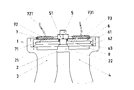
Figure 1 represents, in longitudinal section,
only those parts of a device which are fundamental in
differentiating the invention from the prior art. The
device exhibits a rotationally symmetrical metallic
housing 1. The latter is fastened in an opening of a
container (not shown) by an external thread being
integrally formed, for example, on the housing 1, which
external thread is intended to be screwed into the
container. On the side which faces the container, the
housing 1 i8 terminated by a first diaphragm 2, to which
two oscillating rods 3, 4 projecting into the container
are fixedly connected by their ends in each case and at
a distance apart from one another. The diaphragm 2,
oscillating rods 3, 4 and at least one section of the
housing 1 which directly adjoins the diaphragm 2 are
preferably made of a single casting. A further housing
section ~not shown in the figure) is fixedly connected,
e.g. welded, to the rest of the housing 1.
On the side which faces the housing interior, the
diaphragm 2 exhibits, on its outer border, a stepped ring
21. Consequently, the rigidity of the diaphragm 2 is
increased, and the latter is fixedly clamped in. A6 a
result, only a very small amount of oscillation energy is
transmitted to the housing 1.
Located in the interior of the housing 1 is a
second diaphragm 6 which is, for example, in the form of
an annular disk, arranged parallel to the first diaphragm
2 and on the border of which a tubular coupling piece 61
is integrally formed on in a flush manner. The free end
62 of the coupling piece 61 is bevelled toward the tube
interior, with the result that the coupling ring 61 rests
on the first diaphragm 2 merely by means of an outer
annular edge 63.
The second diaphragm 6 and the coupling piece 61
consist of an electrically conductive material, e.g. a
suitable metal such as stainless steel.
A piezoelectric element 7 in the form of an
2 1 75303
-- 7
annular di~k is fixed, e.g. adhesively bonded or
soldered, on the second diaphragm 6. On the side which
faces the diaphragm, said piezoelectric element exhibits
a first electrode 71 which is in the form of an annular
disk and electrically connects the piezoelectric element
to the second diaphragm 6 and, via the coupling piece 61
and the first diaphragm 2, to the housing 1. Located on
that annular-disk surface of the piezoelectric element 7
which is remote from the diaphragm are a second electrode
72, which can be connected to an AC voltage source (not
shown) via a feedline 721, and a third electrode 73,
which can be connected to evaluation electronics (not
æhown) via a further line 731.
Figure 2 shows a plan view of that side of the
piezoelectric element 7 which is remote from the dia-
phragm. The second electrode 72 is in the form of a
reflex-angle ring segment. The third electrode 73 is in
the form of an acute-angle circle segment. There is no
contact between the electrodes 72, 73. The axis of
symmetry 75 of the arrangement of the two electrodes 72,
73 runs perpendicularly with respect to the deflection
direction of the oscillating rods, this direction being
indicated by the arrows 76, 77.
A clamping screw 5, which projects into the
housing interior, is fastened in the center of the first
diaphragm 2. In the exemplary embodiment shown in Figure
1, the clamping screw 5 is welded onto a step 22 which is
integrally formed on in the center of the diaphragm 2 and
is in the form of a disk. Said step protects the thin,
and thus sensitive, diaphragm 2 during the welding
operation. The clamping screw 5 passes through the ~econd
diaphragm 6 and the piezoelectric element 7. There is no
mechanical contact between the clamping screw 5 and the
housing 1. By means of a nut 51 which is screwed onto the
clamping screw 5, against the second diaphragm 6, the
first diaphragm 2 is prestressed slightly and the edge 63
of the coupling piece 61 cuts into the stepped ring 21 of
the diaphragm 2. There is no electrical contact between
the nut 51 and the two electrodes 72, 73. An insulation
2 1 75303
-- 8
ring 8 is located in the central opening of the
piezoelectric element 7. Said ring i8, for example, a
plastic ring which is adheRively bonded into the opening.
The function of the nut 51 may also be fulfilled
by an internal thread which is provided in the center of
the second diaphragm 6 and by means of which the dia-
phragm 6 is screwed onto the clamping screw 5.
The piezoelectric element 7 exhibits a polariza-
tion in the axial direction. It inherently changes its
thickness in dependence on a voltage difference present
in the axial direction. If an AC voltage is present, then
the thickness oscillates. If the thickness increases,
then the diameter of the piezoelectric element 7
decreases; if the thickness decreases, then the diameter
increases corregpon~;ngly.
On account of this oscillation behavior of the
piezoelectric element 7, a voltage difference has the
effect, when said element is installed into the device,
of b~n~;ng the composite element formed by the piezo-
electric element and the second diaphragm 6, the size ofthe fastening surface between the piezoelectric element
7 and the second diaphragm 6 remaining constant.
If a voltage difference which effects an inherent
increase in diameter of the piezoelectric element 7 is
present, then the center of the bending, i.e. at least
one point of intersection of the vertical with the
fastening surface, is on that side of the piezoelectric
element 7 which faces the diaphragm. If a voltage differ-
ence which effects an inherent decrease in the diameter
of the piezoelectric element 7 is present, then the
center of the ben~;ng is on that side of the piezo-
electric element which is remote from the diaphragm.
If an AC voltage is applied to the piezoelectric
element 7, then the composite element performs bending
oscillations of which the loop of oscillation is located
in the center thereof. This ben~;ng oscillation i~
transmitted to the first diaphragm 2 by the clamping
ccrew 5 and the coupling ring 61. The two diaphragms 2,
6 perform in-phase oscillations.
2 1 75303
g
The oscillation energy is utilized directly for
producing the desired mode of oscillation, namely a
bending oscillation. A single piezoelectric element is
sufficient to produce the oscillations.
On account of the ben~;ng oscillations of the
diaphragm 2, the oscillating rods 3, 4 fixed on the first
diaphragm 2 effect oppositely oriented oscillations
transversely with respect to their longitudinal axis. On
account of said oscillations being oriented in different
directions, the alternating forces exerted by each oscil-
lating rod on the diaphragm 2 cancel out. This means that
the clamping is subjected to low mechanical loading, and
no oscillation energy i~ transmitted to the housing 1.
Moreover, the device is not adversely affected by
the oscillating rods 3, 4 being pressed together in-
correctly. This does not result in additional mechanical
stressing~on the fastening surface between the piezo-
electric element 7 and the second diaphragm 6 since the
coupling ring 61 merely rests on the first diaphragm 2.
It is very simple to assemble the device since
all that is required is to fit the second diaphragm 6
onto the clamping screw 5 and tighten the nut 51.
Furthermore, the composite element may be easily
exchanged at any time.
Figure 3 represents, in longitudinal section, the
fundamental parts of another device. It is only the
fastening means by which the second diaphragm is fixed on
the first diaphragm which render this device different
from the variant represented in Figure 1.
In the center of a second diaphragm 6' in the
form of a disk, a cylindrical stub 65 is integrally
formed on the side which faces the first diaphragm 2. The
second diaphragm 6' exhibits an external thread 64 which
is screwed into an internal thread 11 of the housing 1,
the diaphragm 6' being screwed into the housing 1 to such
an extent that the first diaphragm 2 is prestre~ed
~lightly.
In this exemplary embodiment, use is made of a
piezoelectric element 7' in the form of a disk. Disk-like
2 1 75303
- 10 -
piezoelectric elements 7' are more cost-effective and
slightly more sturdy than those in the form of annular
disks. Electrodes 71', 72' in the form of disks and
circle segments, respectively, are used here instead of
the electrodes 71, 72, in the form of annular disks and
ring segments, respectively, of the exemplary embodiment
of Figure 1.
The insulation 8, which is required in the
exemplary embodiment represented in Figure 1, of the
piezoelectric element 7 and of the electrodes 72, 73 in
Figure 1 with respect to the clamping screw 5 is dis-
pensed with.
The mode of oscillation produced i~ identical to
that in the case of the device of Figure 1. However, the
oscillations are transmitted by the stub 65 alone. The
diaphragm 6 is fixedly clamped into the housing 1 by the
screw-connection, with the result that only a very small
amount of oscillation energy is taken up by the housing
1. For this rea~on, the housing wall exhibits a much
higher degree of mechanical rigidity than the diaphragm
6. The task of isolating the oscillation from the housing
is additionally assisted by the stepped ring 21
integrally formed on the diaphragm 2.