Sélection de la langue

Search

Sommaire du brevet 2175642 

Énoncé de désistement de responsabilité concernant l'information provenant de tiers

Une partie des informations de ce site Web a été fournie par des sources externes. Le gouvernement du Canada n'assume aucune responsabilité concernant la précision, l'actualité ou la fiabilité des informations fournies par les sources externes. Les utilisateurs qui désirent employer cette information devraient consulter directement la source des informations. Le contenu fourni par les sources externes n'est pas assujetti aux exigences sur les langues officielles, la protection des renseignements personnels et l'accessibilité.

Disponibilité de l'Abrégé et des Revendications

L'apparition de différences dans le texte et l'image des Revendications et de l'Abrégé dépend du moment auquel le document est publié. Les textes des Revendications et de l'Abrégé sont affichés :

  • lorsque la demande peut être examinée par le public;
  • lorsque le brevet est émis (délivrance).
(12) Brevet: (11) CA 2175642
(54) Titre français: BAGUE DE GRAISSAGE DE LA ROTULE D'UN DOUBLE JOINT DE CARDAN
(54) Titre anglais: DOUBLE CARDAN UNIVERSAL JOINT BALL AND SOCKET SEAL
Statut: Durée expirée - au-delà du délai suivant l'octroi
Données bibliographiques
(51) Classification internationale des brevets (CIB):
  • F16D 3/84 (2006.01)
  • F16C 11/06 (2006.01)
  • F16D 3/32 (2006.01)
(72) Inventeurs :
  • MAYHEW, ROGER D. (Etats-Unis d'Amérique)
(73) Titulaires :
  • WEASLER ENGINEERING, INC.
(71) Demandeurs :
  • WEASLER ENGINEERING, INC. (Etats-Unis d'Amérique)
(74) Agent: LAVERY, DE BILLY, LLP
(74) Co-agent:
(45) Délivré: 2003-02-04
(22) Date de dépôt: 1996-05-02
(41) Mise à la disponibilité du public: 1997-04-26
Requête d'examen: 1998-04-07
Licence disponible: S.O.
Cédé au domaine public: S.O.
(25) Langue des documents déposés: Anglais

Traité de coopération en matière de brevets (PCT): Non

(30) Données de priorité de la demande:
Numéro de la demande Pays / territoire Date
08/548,222 (Etats-Unis d'Amérique) 1995-10-25

Abrégés

Abrégé français

Un joint d'étanchéité en élastomère pour un appareil de centrage de bille et de douille d'un joint universel à vitesse constante et à double cardan présente des stries rayonnantes à partir d'un trou dans lequel la bille est reçue qui créent des doigts qui se plient pour frotter contre la bille et retenir la graisse dans le joint d'étanchéité alors que le joint est tourné à travers un angle.


Abrégé anglais

An elastomeric seal for a ball and socket centering apparatus of a double cardan constant velocity universal joint has slits radiating from a hole in which the ball is received which create fingers that flex to wipe against the ball and retain grease in the seal as the joint is rotated through an angle.

Revendications

Note : Les revendications sont présentées dans la langue officielle dans laquelle elles ont été soumises.


CLAIMS
1. In an elastomeric seal for a ball and socket
centering apparatus of a double cardan constant velocity
universal joint having one end secured to
said socket and an opposite end in contact with said ball, said
opposite end having a wall with a hole therein for
receiving said ball, the improvement wherein at least one
slit is provided in said seal extending radially
from said hole within said seal.
2. The seal of claim 1, wherein eight
equiangularly spaced slits radiate from said hole.
3. The seal of claim 1, wherein a ridge
surrounds said hole on a socket side of said hole and
said slit extends through said ridge.
4. The seal of claim 1, wherein said seal
is generally cup shaped having an outside diameter at
said one end and wherein said hole is of a diameter less
than said outside diameter, and multiple slits radiate
from said hole.
5. The seal of claim 4, wherein the shape
of said seal conforms to the shape of said socket which
said seal overlies, with said wall of said seal in which
said hole is formed being against an axial face of said
socket.

Description

Note : Les descriptions sont présentées dans la langue officielle dans laquelle elles ont été soumises.

.
DOUBLE CARDAN UNIVERSAL JOINT BALL AND SOCKET SEAL
Backcrround of the Invention
Field of the Invention
This invention relates to seals for the ball and socket
centering apparatus of a double cardan universal joint.
Discussion of the Prior Art
In a typical double cardan or constant velocity universal
joint, two outer yokes are connected to a center yoke by
crosses and the two outer yokes are connected to one another
by a centering apparatus which includes one or more ball and
socket joints. At higher rotational speeds, say above 2000
rpm, it has been found that the joint between a ball and
socket needs lubrication to have a reasonable working life.
A typical bellows type of seal for the ball and socket of
a constant velocity universal joint is disclosed in U.S.
Patent No. 4,276,759. In this type of seal, both ends of the
seal are secured to relatively moving parts of the centering
apparatus and neither end wipes on the ball of the centering
QH3~203479.1

2
apparatus. At high speeds, if the lubricant is concentrated
on one side of the bellows type of seal, the seal will move
radially due to centrifugal force and the seal will ultimately
fail. Therefore, the best seal design for high speeds should
have a minimum radius or diameter to attenuate undesirable
centrifugal forces and should be rigid enough to withstand the
centrifugal forces which inevitably do result.
Another previous solution has been to use a bellows type
seal but in which the smaller diameter of the seal wipes
against the ball or against the base of the ball. However,
with a double cardan universal joint, the motion of the ball
relative to the socket as the CV joint is flexed through an
angle has an axial component. The import of this is that the
sealing surface of the seal, if it is restrained against
movement relative to the socket, changes in diameter. If the
sealing surface diameter is constant, then the seal has to
move axially. A problem with these types of seals is that at
higher rotational speeds, for example 3,000 rpm at an angle of
about 15° or more, the constant flexing of the seal (2 times
per revolution) can cause heating in the elastomer of the seal
and ultimate failure. Also, the center yoke size must be kept
at a minimum length in a universal joint for practical and
functional reasons, so space is at a premium inside the
universal joint.
QB3\203479.1

3
Summary of the Invention
The present invention provides a seal which keeps the
flexing of the elastomer to a minimum at higher angles in
order to keep the heat build-up in the elastomer to a minimum.
The seal of the invention is mounted on the socket in the
usual manner. However, the seal of the invention fits close
to the neck of the ball in order to have the smallest radius
and, as the ball moves axially, the inside diameter of the
seal is required to change in diameter, and may also change
shape by becoming more elliptical or elongated. In order to
accommodate these changes, the inside diameter of the seal has
at least one slit formed around it. This allows the seal
sections to follow the ball and wipe the grease on the ball to
keep it on the socket side of the seal.
In preferred aspect, multiple slits are provided which
extend radially to define fingers between them which are
hingedly biased against the ball. Preferably, a ridge
surrounds the hole on a socket side of the hole and the slit
extends through the ridge. The ridge acts to wipe grease back
on the ball as the ridge is biased against the ball by the
finger.
In another preferred aspect, the seal is generally cup
shaped, having an outside diameter at said one end and the
hole at the other end being of a smaller diameter. The shape
of the seal preferably conforms to the shape of the socket
which the seal overlies, with a face of the seal in which the
hole is formed being against an axial face of the socket.
QB3\203479.1

~ 1'~ ~ ~ ~'~
4
Thereby, the seal is not susceptible to grease accumulating in
open pockets of the seal or localized areas of it, thereby
avoiding subjecting the seal to the centrifugal forces which
can stretch and fatigue it into failure.
These and other objects and advantages of the invention
will be apparent from the detailed description and drawings.
Brief Description of the Drawings
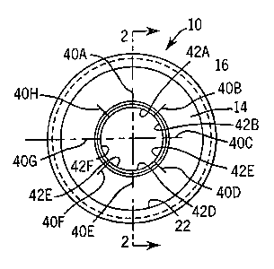
Fig. 1 illustrates a front plan view of a seal
incorporating the invention;
Fig. 2 illustrates a side plan view partially in section
of the seal of Fig. 1;
Fig. 3 illustrates a double cardan joint incorporating a
seal of the invention in a straight position; and
Fig. 4 illustrates the joint of Fig. 3 in an angled
position.
Detailed Description of the Preferred Embodiments
Figs. 1 and 2 illustrate a seal 10 of the invention by
itself, without having been assembled to a constant velocity
universal joint. The seal 10 is generally cup shaped having
been formed from a single piece of elastomeric material.
The seal 10 has an outside diameter end 12 which is
axially spaced from its inside diameter end 14. A flange 16
surrounds the outside diameter end 12 and a ridge 18 surrounds
hole 20 in the inside diameter end 14 on the socket side of
the end 14. A generally cylindrical intermediate section 22
joins the ends 12 and 14, with a radiused corner 24 joining
QB3\203479.1

2~'~~~~~
the end 14 to the intermediate section 22. The hole 20 is
generally conical (as seen at the end 43 of finger 42A in Fig.
2) at an angle of about 15 degrees to horizontal and tapering
outwardly in the direction toward the larger diameter end 12.
5 As such, the intersection of the hole 20 with the ridge 18
forms an edge 26 which is positively raked against the ball so
as to wipe grease off of the ball 30 back toward the socket
32.
Radiating from the hole 20 equiangularly spaced at 45°
are 8 slits 40A-H, which are each approximately .180 inches
long in the preferred embodiment. As used herein, "radiating"
means that they emanate radially from the hole 20. The slits
40A-H lend flexibility to the material of the seal 10 around
the hole 20 and relieve the hole 20 from stretching
circumferentially to accommodate movements of the ball 30
relative to the socket 32. Rather than stretching, the
fingers 42A-H defined between the slits 40A-H can hinge about
the base of the adjacent slits 40A-H which define those
fingers to remain in contact with the ball 30 through the
entire range of motion of the ball 30 relative to the socket
32. The material of the seal 10 is sufficiently stiff and
resilient to bias the fingers 42A-H against the ball. As
such, the surface of the ball 30 which is rotating out of the
socket 32 is wiped by the edge 26 on the respective finger
42A-H which is sliding against the exiting surface of the ball
30, to retain the grease on that surface inside of the seal
10.
QB3\203479.1

CA 02175642 2001-03-08
6
This wiping motion is not perfect so that occasionally
grease does have to be replenished to the seal 10. This can
be accomplished via the lubrication system of the joint, for
example as more specifically,described in U.S. Patent No.
4,781,662. However, the seal does maintain the ball and socket
seal lubricated for useful periods at high speed.
Figs. 3 and 4 illustrate a seal 10 of the invention
assembled in a double universal joint. Briefly, the joint
includes outer yokes 60 and 62 which are journalled to a
center yoke 64 by respective crosses 66 and 68. Ball 30 of
yoke 60 slides in socket 32 of yoke 62 to keep the yokes 60
and 62 equiangular relative to the center yoke 64. Details of
a universal joint similar to this one are described in the
aforementioned U.S. Patent No. 4,781,662. It should, however,
be understood that the seal 10 could be applied to the ball
and socket joint in other types of universal joints.
The outside diameter end 12 is secured to the socket .32
by any suitable means; for example, a spring retaining band
46. The band 46 compresses the portion of sleeve 22 adjacent
to flange 16 down into an external groove defined on the
socket 32. This creates a fluid tight connection between the
seal 10 and the socket 32, while flange 16 helps prevent the
seal 10 from sliding axially under the band 46.
End 14 lays flat against the axial face of socket 32 with
hole 20 adjacent to the neck portion of the ball 30 and edge
26 contacting the ball 30. In the position shown in Fig. 3,
QB3\203479.1

21'~5~~
fingers 42A-H are preferably relaxed, and all lay in the plane
of the end 14. When the joint is made to assume an angle, for
example as in Fig. 4, the fingers 42A-H flex independently of
one another so as to accommodate the movement of the ball 30
relative to the socket 32, as shown in Fig. 4. This movement
changes the size and shape of the line on the ball 30 where
sealing with the seal 10 takes place. However, the seal 10
stays in contact with the ball 30 without stretching along the
periphery of the hole 20.
Preferably, the seal 10 is made from neoprene with a
hardness of 60 durometer shore A. The wall thickness of the
seal 10 is preferably nominally .060 inches, and the height of
the ridge 18 is preferably nominally .031 inches.
Many modifications and variations to the preferred
embodiment will be apparent to those school in the art. For
example, more or less than 8 slits could be provided in a seal
of the invention, and depending upon the application, the
seals need not be directed along perfectly radial lines.
Thus, the invention should not be limited to the embodiment
described, but should be defined by the claims which follow.
QB3\203479.1

Dessin représentatif
Une figure unique qui représente un dessin illustrant l'invention.
États administratifs

2024-08-01 : Dans le cadre de la transition vers les Brevets de nouvelle génération (BNG), la base de données sur les brevets canadiens (BDBC) contient désormais un Historique d'événement plus détaillé, qui reproduit le Journal des événements de notre nouvelle solution interne.

Veuillez noter que les événements débutant par « Inactive : » se réfèrent à des événements qui ne sont plus utilisés dans notre nouvelle solution interne.

Pour une meilleure compréhension de l'état de la demande ou brevet qui figure sur cette page, la rubrique Mise en garde , et les descriptions de Brevet , Historique d'événement , Taxes périodiques et Historique des paiements devraient être consultées.

Historique d'événement

Description Date
Inactive : Regroupement d'agents 2018-09-01
Inactive : Regroupement d'agents 2018-08-30
Inactive : Périmé (brevet - nouvelle loi) 2016-05-02
Inactive : CIB de MCD 2006-03-12
Accordé par délivrance 2003-02-04
Inactive : Page couverture publiée 2003-02-03
Préoctroi 2002-11-15
Inactive : Taxe finale reçue 2002-11-15
Un avis d'acceptation est envoyé 2002-10-09
Lettre envoyée 2002-10-09
Un avis d'acceptation est envoyé 2002-10-09
Inactive : Approuvée aux fins d'acceptation (AFA) 2002-09-30
Modification reçue - modification volontaire 2002-06-27
Inactive : Dem. de l'examinateur par.30(2) Règles 2002-01-29
Modification reçue - modification volontaire 2001-11-14
Inactive : Dem. de l'examinateur par.30(2) Règles 2001-05-16
Modification reçue - modification volontaire 2001-03-08
Inactive : Dem. de l'examinateur par.30(2) Règles 2000-09-12
Inactive : Renseign. sur l'état - Complets dès date d'ent. journ. 1998-04-24
Lettre envoyée 1998-04-24
Inactive : Dem. traitée sur TS dès date d'ent. journal 1998-04-24
Toutes les exigences pour l'examen - jugée conforme 1998-04-07
Exigences pour une requête d'examen - jugée conforme 1998-04-07
Demande publiée (accessible au public) 1997-04-26

Historique d'abandonnement

Il n'y a pas d'historique d'abandonnement

Taxes périodiques

Le dernier paiement a été reçu le 2002-03-20

Avis : Si le paiement en totalité n'a pas été reçu au plus tard à la date indiquée, une taxe supplémentaire peut être imposée, soit une des taxes suivantes :

  • taxe de rétablissement ;
  • taxe pour paiement en souffrance ; ou
  • taxe additionnelle pour le renversement d'une péremption réputée.

Veuillez vous référer à la page web des taxes sur les brevets de l'OPIC pour voir tous les montants actuels des taxes.

Titulaires au dossier

Les titulaires actuels et antérieures au dossier sont affichés en ordre alphabétique.

Titulaires actuels au dossier
WEASLER ENGINEERING, INC.
Titulaires antérieures au dossier
ROGER D. MAYHEW
Les propriétaires antérieurs qui ne figurent pas dans la liste des « Propriétaires au dossier » apparaîtront dans d'autres documents au dossier.
Documents

Pour visionner les fichiers sélectionnés, entrer le code reCAPTCHA :


Pour visualiser une image, cliquer sur un lien dans la colonne description du document. Pour télécharger l'image (les images), cliquer l'une ou plusieurs cases à cocher dans la première colonne et ensuite cliquer sur le bouton "Télécharger sélection en format PDF (archive Zip)" ou le bouton "Télécharger sélection (en un fichier PDF fusionné)".

Liste des documents de brevet publiés et non publiés sur la BDBC .

Si vous avez des difficultés à accéder au contenu, veuillez communiquer avec le Centre de services à la clientèle au 1-866-997-1936, ou envoyer un courriel au Centre de service à la clientèle de l'OPIC.


Description du
Document 
Date
(aaaa-mm-jj) 
Nombre de pages   Taille de l'image (Ko) 
Page couverture 2003-01-03 1 33
Description 2001-03-08 7 238
Revendications 2001-03-08 1 31
Abrégé 2002-01-29 1 10
Abrégé 1996-08-12 1 10
Description 1996-08-12 7 233
Page couverture 1996-08-12 1 16
Revendications 1996-08-12 2 36
Dessins 1996-08-12 1 54
Dessin représentatif 2002-10-01 1 10
Page couverture 1998-07-08 1 16
Revendications 2001-11-14 1 27
Revendications 2002-06-27 1 28
Dessin représentatif 1998-03-27 1 21
Rappel de taxe de maintien due 1998-01-05 1 111
Accusé de réception de la requête d'examen 1998-04-24 1 178
Avis du commissaire - Demande jugée acceptable 2002-10-09 1 163
Taxes 2003-05-02 1 37
Taxes 2002-03-20 1 40
Correspondance 2002-11-15 1 30
Taxes 1998-04-06 1 50
Taxes 1999-03-11 1 47
Taxes 2001-03-14 1 38
Taxes 2000-04-11 1 40
Taxes 2004-03-30 1 35
Taxes 2005-02-15 1 34
Taxes 2005-12-22 1 52
Taxes 2007-05-02 1 45
Taxes 2008-05-01 1 46
Taxes 2009-04-27 1 44