Sélection de la langue

Search

Sommaire du brevet 2175673 

Énoncé de désistement de responsabilité concernant l'information provenant de tiers

Une partie des informations de ce site Web a été fournie par des sources externes. Le gouvernement du Canada n'assume aucune responsabilité concernant la précision, l'actualité ou la fiabilité des informations fournies par les sources externes. Les utilisateurs qui désirent employer cette information devraient consulter directement la source des informations. Le contenu fourni par les sources externes n'est pas assujetti aux exigences sur les langues officielles, la protection des renseignements personnels et l'accessibilité.

Disponibilité de l'Abrégé et des Revendications

L'apparition de différences dans le texte et l'image des Revendications et de l'Abrégé dépend du moment auquel le document est publié. Les textes des Revendications et de l'Abrégé sont affichés :

  • lorsque la demande peut être examinée par le public;
  • lorsque le brevet est émis (délivrance).
(12) Brevet: (11) CA 2175673
(54) Titre français: AMELIORATIONS APPORTEES A DES TIRANTS D'ANCRAGE
(54) Titre anglais: IMPROVEMENTS IN GROUND ANCHORS
Statut: Durée expirée - au-delà du délai suivant l'octroi
Données bibliographiques
(51) Classification internationale des brevets (CIB):
  • E02D 5/80 (2006.01)
  • E02D 5/74 (2006.01)
  • F16G 11/00 (2006.01)
  • F16G 11/10 (2006.01)
(72) Inventeurs :
  • AGG, CHARLES SIMON JAMES (Royaume-Uni)
(73) Titulaires :
  • PLATIPUS ANCHORS LIMITED
(71) Demandeurs :
  • PLATIPUS ANCHORS LIMITED (Royaume-Uni)
(74) Agent: RICHES, MCKENZIE & HERBERT LLP
(74) Co-agent:
(45) Délivré: 2004-12-07
(86) Date de dépôt PCT: 1994-05-18
(87) Mise à la disponibilité du public: 1995-05-11
Requête d'examen: 2000-04-03
Licence disponible: S.O.
Cédé au domaine public: S.O.
(25) Langue des documents déposés: Anglais

Traité de coopération en matière de brevets (PCT): Oui
(86) Numéro de la demande PCT: PCT/GB1994/001066
(87) Numéro de publication internationale PCT: WO 1995012713
(85) Entrée nationale: 1996-05-02

(30) Données de priorité de la demande:
Numéro de la demande Pays / territoire Date
9322642.1 (Royaume-Uni) 1993-11-03

Abrégés

Abrégé français

L'invention se rapporte à des tirants d'ancrage (10) du type de ceux qui sont fixés à des câbles et à des barres, enfoncés dans le sol puis basculés transversalement par tension du câble. Un tirant d'ancrage comprend un corps (11) généralement de coupe triangulaire, s'étendant sensiblement sur sa longueur, doté de côtés généralement concaves ainsi que d'une surface inférieure continue convexe s'étendant à partir d'un bord de la portion du corps où se rencontrent les côtés et la surface inférieure, jusqu'au bord opposé.


Abrégé anglais


The invention relates to ground anchors (10) of the type which are attached to cables and rods and driven into the ground and tilted
transversely by tensioning the cable. A ground anchor comprising a body portion (11) having a generally triangular cross section extending
substantially along its length having generally concave sides and a continuous convex lower surface from one edge of the body portion
where the sides and lower suface meet to an opposite edge.

Revendications

Note : Les revendications sont présentées dans la langue officielle dans laquelle elles ont été soumises.


-6-
The embodiments of the invention in which an exclusive
property or privilege is claimed are defined as follows:
1. A ground anchor comprising a body portion having a
generally triangular cross-section extending substantially
along a length thereof having generally concave sides and a
continuous convex lower surface from one edge of the body
portion where the sides and lower surface meet to an
opposite edge.
2. An anchor as claimed in claim 1 in which the edges of
said body portion curve upwardly where the sides and lower
surface meet.
3. An anchor as claimed in claim 1 in which the edges of
said body portions angle upwardly where the sides and lower
surface meet.
4. An anchor as claimed in any one of claims 1 to 3 in
which edges of said body portion where the sides and lower
surface meet are rounded.
5. An anchor as claimed in any one of claims 1 to 4
further comprising a driving edge formed at one end of said
body portion.
6. An anchor as claimed in any one of claims 1 to 5 in
which the body portion extends upwardly to form a keel
member in which is formed an anchor eye.
7. An anchor as claimed in any one of claims 1 to 5 in
which a keel member is formed on the body portion in which
is formed a socket.

-7-
8. An anchor as claimed in claim 6 or claim 7 in which the
keel member is convergent in a horizontal or vertical plane
from the eye portion or socket to the driving edge.
9. A ground anchor comprising a body portion having a
generally triangular cross-section extending substantially
along a length thereof and having generally concave sides
and a lower surface, said lower surface and said concave
sides meeting to form a first edge and a second edge,
wherein said lower surface is continuously convex between
said first and second edges.
10. An anchor as claimed in claim 9 in which said first
edge and said second edge curve upwardly from a horizontal
plane.
11. An anchor as claimed in claim 10 wherein said first and
second edges are rounded.
12. An anchor as claimed in claim 11 further comprising a
driving edge formed at an end of said body portion.
13. An anchor as claimed in claim 12 wherein said body
portion extends upwardly to form a keel member having an
anchor eye.
14. An anchor as claimed in claim 13 wherein said keel
member tapers downwardly to said driving edge.
15. An anchor as claimed in claim 14 wherein said keel
member is convergent to the horizontal plane.

-8-
16. An anchor as claimed in claim 12 wherein said body
portion includes a keel member having a socket.
17. An anchor as claimed in claim 16 wherein said keel
member tapers downwardly to said driving edge.
18. An anchor as claimed in claim 17 wherein said keel
member is convergent to the horizontal plane.
19. An anchor as claimed in claim 6 or claim 7 in which the
keel member is convergent in a horizontal and vertical plane
from the eye portion or socket to the driving edge.

Description

Note : Les descriptions sont présentées dans la langue officielle dans laquelle elles ont été soumises.

- WO 95112713
217 5 6 7 3 p~lGg94/01066
- 1 -
IMPROVEMENTS IN GROUND ANCHORS
The invention relates to ground anchors of the
type which are attached to cables and rods and driven
into the ground and tilted transversely by tensioning
the cable.
A variety of ground anchors already exist
including tubular anchors, such as those described in
GB-A-1555580 and EP-A-0208153. These anchors are
driven into the ground and then rotated to a
horizontal locked position. As the surface area of
these anchors is not particularly large, they are not
appropriate for some uses where a particular degree
of strength and resistance to removal from the ground
is required.
Improvements have been made to such anchors
which resulted in the addition of wings to provide a
greater planar or surface area to resist the anchors
from being pulled from the ground once in their
tilted locked position. Examples of such wing
anchors are known from EP-A-0313936, US-A-4574539 and
US-A-3282002. Each of these anchors has different
specific features which enable the anchors either to
be easily driven into the ground, to prevent its
withdrawal therefrom or to ease the ability of rotate
the anchor once embedded in the ground.
However, in hard ground conditions wing-type
anchors are not generally suitable because of the
increase in the quantity of ground media to be
moved. For such conditions high capacity small
profile anchors, such as the original tubular
anchors, are most suitable.
It is therefore an object of the present
invention to further improve anchors of the small
profile type in these respects.
according to the invention there is provided a

CA 02175673 2000-OS-09
- 2 -
ground anchor comprising a body portion having a
generally triangular cross-section extending
substantially along its length having generally concave
sides and a continuous convex lower surface from one edge
of the body portion where the sides and lower surface
meet to an opposite edge.
In an aspect of the present invention, there is
provided a ground anchor comprising a body portion having
a generally triangular cross-section extending
substantially ,slong a length thereof and having generally
concave sides ,end a lower surface, said lower surface and
said concave sides meeting to form a first edge and a
second edge, wherein said lower surface is continuously
convex between said first and second edges.
Preferabl:~r the edges of said body portion curve or
angle upwardly where the sides and lower surface meet.
Edges of said body portion where the sides and lower
surface meet a:re preferably rounded.
In a preferred embodiment of the invention the
anchor comprises a driving edge formed at one end of said
body portion.
Preferable the :body portion extends upwardly to form
a keel in which is formed an anchor eye. Alternatively a
keel portion is formed on the body portion in which is
formed a socket=.
The keel rnember is preferably convergent in a
horizontal and;or vertical plane from the eye portion or
socket to the driving edge.
A preferred embodiment of the invention will now be
described, by way of example only, with reference to the
accompanying drawings, in which:-

CA 02175673 2000-OS-09
- 2a -
Fig. 1 is a plan view of an anchor according to the
invention;
Fig. 2 is a side elevation of the anchor of Fig. l;
Fig. 3 is a front elevation of the anchor of Fig. 1;
Fig. 4 is a rear elevation of the anchor of Fig. 1;

_ WO 95/12713 21 l 5 b 7 3
PCT1GB94I01066
- 3 -
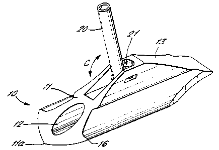
Fig. 5 is a schematic view of the anchor of
Fig. 1 with the eye replaced with a swaged fitting;
Fig. 6 is a partial schematic view of the
swaged fitting of Fig. 5 with parts omitted for
clarity; and
Figs. 7a-7c are schematic views of the
installion steps applied to a prior art anchor.
As shown in Figs. 1-4 the anchor 10 comprises a
generally triangular or bell-shaped body 11 having an
axially extending blind bore 12 for receiving a
driving tool. When viewed from one end, the anchor
10 is seen to have a triangular bell-shaped profile
for a substantial length along its working surface.
The sides of the anchor body 11 are, in profile,
continuously concave from an upper edge of the
working surface to edges 16 where the sides and lower
surface meet. The lower surface of the body I1 is
continuously convex from edge to edge. The edges 16,
may curve or angle slightly upwardly from the
horizontal. These edges 16 may be rounded or edge
beads provided. It is to be noted that the use of
the terms "concave" or "convex" are intended to
include not only inwardly or outwardly rounded
surfaces, but also surfaces which have flat regions
which may be angled to other flat regions but which
overall give an impression of concavity or convexity.
The body I1 extends upwardly to form a high
keel 13 in which is formed an anchor eye 14 to which
a cable may be attached. The high keel 13, which
starts from the anchor eye 14, tapers downwardly
towards a driving edge 15. The driving edge 15 may
be sharpened to a chisel point. The keel 13 may also
converge in the horizontal direction to form a point

WO95112713 2175673
PCT/GB94I01066
- 4 -
as it approaches the driving edge 15. The body
portion 11 has a sharp tapering nose 11a at an end
opposite to the driving edge 15.
In an alternative embodiment of the invention,
as shown in Figs. 5 and 6, the eye 14 is replaced
with a T-shaped swaged fitting 20. The fitting 20 is
inserted into a socket 21 formed in the keel 13 with
the cross bar 22 positioned longitudinally to the
body lI. The fitting 20 can then be rotated through
90° to the position shown in Figs. 5 and 6 whereby
the T-piece 22 is anchored in the socket 21 under the
keel 13. The fitting 20 can then pivot in the
direction of the arrow C.
In this embodiment of the invention, the
working surface of the anchor extends to below the
keel 13.
In use, a cable or rod is attached to the eye
portion 14 or swaged fitting 20 and a driving rod is
inserted into the bore 12. The anchor 10 is driven
into the ground, driving edge 15 first to its
installed position, by applying a force to the
driving rod. Fig. 7a illustrates the installed
position of a prior art anchor.
The driving edge 15 splits the ground media by
way of separating the upper side and lower side and
compresses the media out of the way. This enhances
the ability of the anchor 10 to drive more quickly
and easily through harder media. The high keel 13
further enhances significantly the ability of the
anchor 10 to drive straight through difficult
anchoring media.
Once the anchor 10 has reached its desired
depth, the drive rod is removed from the bore 12. A
pulling force is applied to the cable or rod which
causes the anchor 10 to rotate in the ground to a
generally horizontal load locked position (see Fig.

_ WO 95/12713 217 5 6 7 3
- 5 -
PCT/GB94/01066
7A-B). Once the sharp nose lla of the body 11 bites
the back of the hole into which the anchor 10 is
driven, this forms a fulcrum for the anchor 10 to
turn about. The upwardly curved edges 16 of the
anchor body 11 help to consolidate the turn of the
anchor 10.
The triangular or bell-shaped working surface
area of the anchor 10 offers a significant increase
in potential load over traditional tube-style anchors
whilst the anchor remains a small profile anchor
which is necessary for hard ground conditions. The
shaped surface offers high load possibilities for a
small surface area anchor by focusing the frustrum of
soil more clearly.
The rounded edges 16 of the anchor 10 further
enhance the frustum area and reduce spill-off during
high loadings and therefore reduce mechanical shear.
The anchor 10 may be made from any suitable
material depending on its required use, such as
iron/steel, copper and brass based alloys, aluminium,
non-ferous materials and possibly non-metallic
materials.
30

Dessin représentatif
Une figure unique qui représente un dessin illustrant l'invention.
États administratifs

2024-08-01 : Dans le cadre de la transition vers les Brevets de nouvelle génération (BNG), la base de données sur les brevets canadiens (BDBC) contient désormais un Historique d'événement plus détaillé, qui reproduit le Journal des événements de notre nouvelle solution interne.

Veuillez noter que les événements débutant par « Inactive : » se réfèrent à des événements qui ne sont plus utilisés dans notre nouvelle solution interne.

Pour une meilleure compréhension de l'état de la demande ou brevet qui figure sur cette page, la rubrique Mise en garde , et les descriptions de Brevet , Historique d'événement , Taxes périodiques et Historique des paiements devraient être consultées.

Historique d'événement

Description Date
Inactive : Périmé (brevet - nouvelle loi) 2014-05-18
Inactive : CIB de MCD 2006-03-12
Accordé par délivrance 2004-12-07
Inactive : Page couverture publiée 2004-12-06
Préoctroi 2004-09-22
Inactive : Taxe finale reçue 2004-09-22
Un avis d'acceptation est envoyé 2004-08-04
Lettre envoyée 2004-08-04
Un avis d'acceptation est envoyé 2004-08-04
Inactive : Approuvée aux fins d'acceptation (AFA) 2004-07-15
Modification reçue - modification volontaire 2003-11-25
Inactive : Dem. de l'examinateur par.30(2) Règles 2003-10-07
Modification reçue - modification volontaire 2003-06-06
Inactive : Dem. de l'examinateur par.30(2) Règles 2002-12-06
Modification reçue - modification volontaire 2000-06-27
Modification reçue - modification volontaire 2000-05-09
Inactive : Dem. traitée sur TS dès date d'ent. journal 2000-05-03
Lettre envoyée 2000-05-03
Inactive : Renseign. sur l'état - Complets dès date d'ent. journ. 2000-05-03
Exigences pour une requête d'examen - jugée conforme 2000-04-03
Toutes les exigences pour l'examen - jugée conforme 2000-04-03
Lettre envoyée 1999-11-08
Exigences de rétablissement - réputé conforme pour tous les motifs d'abandon 1999-10-28
Réputée abandonnée - omission de répondre à un avis sur les taxes pour le maintien en état 1999-05-18
Demande publiée (accessible au public) 1995-05-11

Historique d'abandonnement

Date d'abandonnement Raison Date de rétablissement
1999-05-18

Taxes périodiques

Le dernier paiement a été reçu le 

Avis : Si le paiement en totalité n'a pas été reçu au plus tard à la date indiquée, une taxe supplémentaire peut être imposée, soit une des taxes suivantes :

  • taxe de rétablissement ;
  • taxe pour paiement en souffrance ; ou
  • taxe additionnelle pour le renversement d'une péremption réputée.

Veuillez vous référer à la page web des taxes sur les brevets de l'OPIC pour voir tous les montants actuels des taxes.

Titulaires au dossier

Les titulaires actuels et antérieures au dossier sont affichés en ordre alphabétique.

Titulaires actuels au dossier
PLATIPUS ANCHORS LIMITED
Titulaires antérieures au dossier
CHARLES SIMON JAMES AGG
Les propriétaires antérieurs qui ne figurent pas dans la liste des « Propriétaires au dossier » apparaîtront dans d'autres documents au dossier.
Documents

Pour visionner les fichiers sélectionnés, entrer le code reCAPTCHA :


Pour visualiser une image, cliquer sur un lien dans la colonne description du document. Pour télécharger l'image (les images), cliquer l'une ou plusieurs cases à cocher dans la première colonne et ensuite cliquer sur le bouton "Télécharger sélection en format PDF (archive Zip)" ou le bouton "Télécharger sélection (en un fichier PDF fusionné)".

Liste des documents de brevet publiés et non publiés sur la BDBC .

Si vous avez des difficultés à accéder au contenu, veuillez communiquer avec le Centre de services à la clientèle au 1-866-997-1936, ou envoyer un courriel au Centre de service à la clientèle de l'OPIC.


Description du
Document 
Date
(aaaa-mm-jj) 
Nombre de pages   Taille de l'image (Ko) 
Dessin représentatif 1997-06-17 1 4
Revendications 2003-06-06 3 76
Dessins 2003-06-06 3 49
Page couverture 1996-08-08 1 16
Abrégé 1995-05-11 1 40
Revendications 1995-05-11 2 35
Description 1995-05-11 5 182
Dessins 1995-05-11 3 48
Revendications 2000-06-27 3 74
Revendications 2000-05-09 3 67
Description 2000-05-09 6 195
Dessin représentatif 2004-07-15 1 11
Page couverture 2004-11-02 1 40
Courtoisie - Lettre d'abandon (taxe de maintien en état) 1999-06-15 1 186
Avis de retablissement 1999-11-08 1 171
Accusé de réception de la requête d'examen 2000-05-03 1 178
Avis du commissaire - Demande jugée acceptable 2004-08-04 1 162
PCT 1996-05-02 8 250
Taxes 2003-05-15 1 32
Taxes 2002-05-13 1 37
Taxes 2001-04-30 1 35
Taxes 1998-05-15 1 36
Taxes 2000-05-17 1 36
Taxes 1999-10-28 1 44
Taxes 2004-05-13 1 35
Correspondance 2004-09-22 1 33
Taxes 2005-05-11 1 36
Taxes 2006-05-02 1 34
Taxes 2007-04-19 1 44
Taxes 2008-04-30 1 53
Taxes 2009-04-21 1 54
Taxes 1997-05-13 1 41
Taxes 1996-05-02 1 49