Sélection de la langue

Search

Sommaire du brevet 2176002 

Énoncé de désistement de responsabilité concernant l'information provenant de tiers

Une partie des informations de ce site Web a été fournie par des sources externes. Le gouvernement du Canada n'assume aucune responsabilité concernant la précision, l'actualité ou la fiabilité des informations fournies par les sources externes. Les utilisateurs qui désirent employer cette information devraient consulter directement la source des informations. Le contenu fourni par les sources externes n'est pas assujetti aux exigences sur les langues officielles, la protection des renseignements personnels et l'accessibilité.

Disponibilité de l'Abrégé et des Revendications

L'apparition de différences dans le texte et l'image des Revendications et de l'Abrégé dépend du moment auquel le document est publié. Les textes des Revendications et de l'Abrégé sont affichés :

  • lorsque la demande peut être examinée par le public;
  • lorsque le brevet est émis (délivrance).
(12) Demande de brevet: (11) CA 2176002
(54) Titre français: CONTENEUR DE TRANSPORT ET DE STOCKAGE
(54) Titre anglais: TRANSPORT AND STORAGE CONTAINER
Statut: Réputée abandonnée et au-delà du délai pour le rétablissement - en attente de la réponse à l’avis de communication rejetée
Données bibliographiques
(51) Classification internationale des brevets (CIB):
  • B65D 06/40 (2006.01)
  • B65D 25/00 (2006.01)
(72) Inventeurs :
  • POLZL, FRANZ (Autriche)
(73) Titulaires :
  • STEINER FREIZEITMOBEL GESELLSCHAFT M.B.H. & CO. KG.
(71) Demandeurs :
  • STEINER FREIZEITMOBEL GESELLSCHAFT M.B.H. & CO. KG. (Autriche)
(74) Agent: RICHES, MCKENZIE & HERBERT LLP
(74) Co-agent:
(45) Délivré:
(86) Date de dépôt PCT: 1994-11-17
(87) Mise à la disponibilité du public: 1995-05-26
Licence disponible: S.O.
Cédé au domaine public: S.O.
(25) Langue des documents déposés: Anglais

Traité de coopération en matière de brevets (PCT): Oui
(86) Numéro de la demande PCT: PCT/AT1994/000172
(87) Numéro de publication internationale PCT: AT1994000172
(85) Entrée nationale: 1996-05-07

(30) Données de priorité de la demande:
Numéro de la demande Pays / territoire Date
A 2341/93 (Autriche) 1993-11-19

Abrégés

Abrégé français

L'invention concerne un conteneur de transport et de stockage destiné à recevoir des marchandises de détail et elle a pour objet de permettre de prélever de telles marchandises à travers une ouverture latérale, même lorsque les réservoirs sont empilés, le réservoir comportant sur l'une des parois latérales (4) ou des parois terminales (6, 7) une trappe (8) qui est plus petite, au moins d'une valeur égale à la longueur verticale d'une fente de réception (13), que la hauteur (16) de l'orifice de la paroi latérale (4) ou des parois avant (6, 7). La trappe (8) se déplace vers le haut dans l'ouverture et pivote dans des fentes de réception (12, 13) au moyen de tourillons (9) et elle est bloquée dans l'orifice au moyen d'axes de fermeture (10, 11). Le conteneur doit également être recyclable, ce qui est rendu possible par le fait qu'un seul matériau est utilisé pour sa construction.


Abrégé anglais


The invention concerns a transport and storage container for package freights, the aim
of the invention being to permit such freight material to be removed from containers through an
opening in the side even when the containers are stacked one on top of the other. Disposed in
one of the side walls (4) or face walls (6, 7) is a flap (8) the height of which is less than the
height (16) of the opening by an amount at least equal to the vertical width of a mounting slot
(13) in which the flap is mounted. The flap (8) is mounted by means of bearing pins (9) which
fit in mounting slots (12, 13) so that it can move vertically and pivot and so that it can be
locked in place in the opening by means of locking pins (10, 11). The container proposed also
meets the requirements for ease of recycling by virtue of the fact that only a single material is
use in its construction.

Revendications

Note : Les revendications sont présentées dans la langue officielle dans laquelle elles ont été soumises.


-8-
WHAT IS CLAIMED IS:
1. Transport and storage container with base and side walls (4), in which
at least one side wall (4) forms a frame, which is closed at the top in a known manner, for in-
serting a flap (8) that can be pivoted off, which flap by means of lower bearing pins (9),
projecting on both sides and arranged coaxially relative to one another, engages in bearing eyes
of the frame side parts, and can be inserted by means of locking pins (10,11), projecting on
both sides and arranged above the bearing pins (9), into mounting slots (12,13) of the frame
side parts which are accessible via insertion openings from an outer surface, and the inside
height (16) of the frame of the flap-bearing side wall (4) or face wall (7) is greater than the flap
height (15), and the slot length (17) of the mounting slots (12, 13) is equal to or smaller in
height than the height difference (14) between the frame and flap (8), and at least one of the
mounting slots (13) comprises a restriction (20) as a detent for the corresponding locking pins
(10), and the mounting slots (13) forming the bearing eyes for the bearing pins (9) are designed
in the form of longitudinal slots.
2. Transport and storage container according to Claim 1, characterised in
that the longitudinal slot of the bearing eyes opens upwards into a narrower passage (21) and
the bearing pins (9) have a flattened edge (19) angularly displaced relative to the flap plane that
is adjusted to fit the passage width.
3. Transport and storage container according to Claim 2, characterised in
that the longitudinal slot of the bearing eyes is provided in addition as a mounting slot (13) for
the bottom locking pin (10), whereby the passage (21) forms the detent for this locking pin
(10).
4. Transport and storage container according to one of Claims 1 to 3,
characterised in that the one piece flap (8), the base (1), the side walls (4) and face walls (6, 7)

-9-
are made of the same plastic.
5. Transport and storage container according to one of Claims 1 to 4,
characterised in that flap-bearing face wall (7) together with the other side walls (4) and face
wall (6) is hinged to the base (1) in a known manner able to pivot into the base plane.

Description

Note : Les descriptions sont présentées dans la langue officielle dans laquelle elles ont été soumises.

~ 21 76002
TRANSPORT AND STORAGE CONTAINER
BACKGROUND OF THE INVENTION
Field of the invention
The invention relates to a transport and storage container made of plastic as described in
the preamble of claim 1.
Description of the prior art
A container of this kind is already known from CH-PS-537 842, in which access to the
container is only possible by means of a one-piece slide when the latter is lifted vertically up-
wards either completely or partly. Access through the side opening is not possible when the
containers are stacked on top of one another.
Furtherrnore, a container is known from DE-OS-29 09 136 in which access to the con-
tainer is possible from the side even when the containers are stacked, but the flap itself
comprises at least two parts which are hinge connected. The hinge connection and the locking
mech~ni~m~ are expensive to construct with respect to their manufacture.
SUMMARY OF THE INVENTION
The objective of the invention is to design the opening flap in such a way that the flap is
made in one piece and is easy to install and remove, so that the flap can also be operated when
the containers are stacked, and the entire container, the flap, the connecting system between the
container and the flap and the pivot and locking mechanism, is made from a single material and
all the side walls together with the flaps located therein can be opened into the plane of the base

2l 76oo~
- 2 -
plate.
The objective of the invention is achieved by means of the features described in the
characterising part of claim 1. The surprising advantage is that it is still possible to open the
flaps when the containers are stacked on top of one another and the flap itself is made in one
piece, and thus does not have an expensive folding-door-like construction.
It is also an advantage that expensively formed hinge axes, which are expensive to con-
struct with respect to their manufacture, are not necessary and despite this the pivot-opening
function is maintained.
BRIEF DESCRIPTION OF THE DRAWINGS
For a better understanding of the invention, the latter is explained in more detail with
reference to the embodiments illustrated in the drawings, in which:
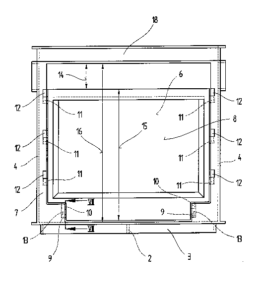
FIG. 1 shows a transport and storage container according to the invention
viewed from above;
FIG. 2 shows the transport and storage container in cross section along the lineII-II in Fig. 1 with the flap removed;
FM. 3 shows the transport and storage container viewed according to arrow III
in Fig. l;
FIG. 4 shows a flap of the transport and storage container according to the in-
vention in a front view;

21 76002
- 3 -
FIG. 5 shows a view of a locking pin of the flap;
FIG. 6 shows the locking pin of the flap, in cross section along the line XI-XI in
Fig. 5;
FM. 7 shows a mount and a bearing pin of the flap in cross section along the
line XII-XII in Fig. 3.
DETAILED DESCRIPTION OF THE PREFERRED EMBODIMENTS
Figs. 1 to 7 show a transport and storage container made of plastic for package freight
with a rectangular base 1 and four walls. The base 1 is holohedrical or lattice-shaped and has
reinforcement ribs 2 on its underside, the outside edge 3 of which is set back relative to the end
walls, so that when the boxes are stacked it can be lowered into an open-topped box and lateral
sliding can be prevented. The two side walls 4 are closed holohedrically or lattice-shaped and
have oval grip openings 5. A face wall 6 is also closed holohedrically or lattice-shaped and also
has a grip opening 5. At least one of the four walls, e.g. another face wall 7, comprises a flap 8.
The latter can be completely folded back so that when it is open access is provided to the con-
tainer from the side and when it is closed it is in alignment with the fixed side wall part.
The flap-bearing face wall 7, containing a flap opening, comprises a known closed
frame. The opening in the frame is rectangular with recessed corners in the region of bearing
pins 9.
The flap 8 itself has lateral bearing pins 9 and locking pins 10, 11 which engage in
mounting slots 12, 13 in the adjoining vertical sides of the frame.
The bottom locking pins 10 and the bearing pins 9 engage in mounting slots 13, e.g.

217~00~2
- 4 -
vertical slots, and are adjustable in height. The other locking pins 11 engage in L-shaped out-
wards projecting mounting slots 12. To enable vertical lifting in the following pivot-opening
movement the height difference 14 between the flap height 15 and the inside height 16 of the
flap opening is greater than or equal to the slot length 17 of the mounting slots 12, 13. A gap in
the outer wall of the container, which remains even when the flap is closed, on the one hand
permits the vertical lifting of the flap in its plane to enable the following pivot opening and on
the other hand forms a grip opening. A horizontal overlying crossbeam 18 of the frame thus
also fulfils the function of a carrying grip.
The bearing pins 9 are cylindrical with flattened edges 19 perpendicular to the flap
plane and form an axis of rotation. The bottom, vertical mounting slot 13 is open at the top, but
has a restriction 20 in the upper opening, which forms a passage 21. The lower part of the
mounting slot 13 is slightly wider than the diameter of the cylindrical bearing pin 9, and thus
vertical movement is possible. The restriction 20 or passage 21 is narrower than the ~ m~ter Of
the bearing pin 9, but has the same width as the bearing pin 9 measured at right angles to the
flattened edges 19. In this way a simple adjustment in height is possible in the broad section up
to the restriction 20 of the mounting slot 13 on vertical lifting and complete vertical removal is
prevented.
If after lifting to unlock the flap 8, the latter is pivoted into the horizontal plane and then
lifted again, only the flattened-edge (smaller) diameter of the bearing pin 9 is operative and can
be guided through the restriction 20 in the mounting slot 13 using a small amount of force. In
this way the flap 8 can be detached from the frame or container or installed in a reverse process.
Directly above the lower bearing pin 9 which forms the axis of rotation a further lock-
ing pin 10 is attached to the flap 8 on each side which has a securing function. It has a prismatic
shape and in cross section comprises a narrower link arm 22 and thicker head 23 (cf. Fig. 7).
The shape corresponds with slightly smaller dimensions to the upper half of the bottom mount-

2176002
s
ing slot 13 and the restricted opening. The similarity of these shapes permits an engagement("snapping-in") on lowering the flap 8 vertically and thus locks the flap 8 in a closed position.
The other locking pins 11 of the flap 8 have a prismatic shape, as shown in particular in
Figs. 5 and 6, and in cross section are rectangular with rounded corners 24, whereby the lower
corners are more rounded to facilitate insertion into the vertical part of the L-shaped mounting
slot 12. The locking pin 11 is narrowed in the middle section 25 on both sides like a cam. The
horizontal part of the L-shaped mounting slot 12 is slightly larger than the corresponding height
of the locking pin 11 and thus simple horizontal insertion and subsequent pivoting of the flap 8
into the side wall plane is possible. The vertical part of the L-shaped mounting slot 12 is the
same size as the narrow side of the locking pin 11. In this way vertical movement is possible
with a small amount of force and there is a "tolerance-free" guiding into the slots, and thereby a
stable (not loose) connection with the side wall frame is made. By means of the cam-shaped
narrowed section the locking pin 11 rests in the mounting slot 12 at four points. Because of the
elasticity of the material relatively high compressive stresses can be achieved by the small bear-
ing surfaces with a small application of force, whereby the flap 8 can be guided precisely and
fixed securely in the closed position in a smooth operation. The flap 8, as described above and
illustrated in the drawings, can of course also be fitted into several side walls. Furthermore, it is
shown that the entire container as described can be made from a single material. This is
achieved in that the flap 8 with its locking and bearing pins 10, 11, 9 is produced in one piece in
a die cast mould according to a known process. The same applies to the container itself. The
use of one material means that once the container is no longer functional it can be recycled eas-
ily.
The construction, which makes it possible to fold all four side walls into the plane of the
base plate and when empty requires much less space is assumed to be known and is not de-
scribed in more detail here.

2I7~002
- 6 -
The combination of side walls which can be folded into the base plane and the flap lo-
cated in at least one of the side walls is possible by means of the above described frame
construction of the remaining part of the wall surrounding the flap.

2176002
- 7 -
LIST OF REFERENCE NUMBERS
base 16 height
2 reinforcement rib 17 slot length
3 outside edge 18 crossbeam
4 side wall 19 flattened edge
grip opening 20 restriction
6 face wall 21 passage
7 face wall 22 link arm
8 flap 23 head
9 bearing pin 24 corner
lockingpin 25 middle section
11 locking pin
12 mounting slot
13 mounting slot
14 height difference
flap height

Dessin représentatif
Une figure unique qui représente un dessin illustrant l'invention.
États administratifs

2024-08-01 : Dans le cadre de la transition vers les Brevets de nouvelle génération (BNG), la base de données sur les brevets canadiens (BDBC) contient désormais un Historique d'événement plus détaillé, qui reproduit le Journal des événements de notre nouvelle solution interne.

Veuillez noter que les événements débutant par « Inactive : » se réfèrent à des événements qui ne sont plus utilisés dans notre nouvelle solution interne.

Pour une meilleure compréhension de l'état de la demande ou brevet qui figure sur cette page, la rubrique Mise en garde , et les descriptions de Brevet , Historique d'événement , Taxes périodiques et Historique des paiements devraient être consultées.

Historique d'événement

Description Date
Inactive : CIB de MCD 2006-03-12
Le délai pour l'annulation est expiré 1998-11-17
Demande non rétablie avant l'échéance 1998-11-17
Réputée abandonnée - omission de répondre à un avis sur les taxes pour le maintien en état 1997-11-17
Demande publiée (accessible au public) 1995-05-26

Historique d'abandonnement

Date d'abandonnement Raison Date de rétablissement
1997-11-17
Titulaires au dossier

Les titulaires actuels et antérieures au dossier sont affichés en ordre alphabétique.

Titulaires actuels au dossier
STEINER FREIZEITMOBEL GESELLSCHAFT M.B.H. & CO. KG.
Titulaires antérieures au dossier
FRANZ POLZL
Les propriétaires antérieurs qui ne figurent pas dans la liste des « Propriétaires au dossier » apparaîtront dans d'autres documents au dossier.
Documents

Pour visionner les fichiers sélectionnés, entrer le code reCAPTCHA :


Pour visualiser une image, cliquer sur un lien dans la colonne description du document (Temporairement non-disponible). Pour télécharger l'image (les images), cliquer l'une ou plusieurs cases à cocher dans la première colonne et ensuite cliquer sur le bouton "Télécharger sélection en format PDF (archive Zip)" ou le bouton "Télécharger sélection (en un fichier PDF fusionné)".

Liste des documents de brevet publiés et non publiés sur la BDBC .

Si vous avez des difficultés à accéder au contenu, veuillez communiquer avec le Centre de services à la clientèle au 1-866-997-1936, ou envoyer un courriel au Centre de service à la clientèle de l'OPIC.

({010=Tous les documents, 020=Au moment du dépôt, 030=Au moment de la mise à la disponibilité du public, 040=À la délivrance, 050=Examen, 060=Correspondance reçue, 070=Divers, 080=Correspondance envoyée, 090=Paiement})


Description du
Document 
Date
(aaaa-mm-jj) 
Nombre de pages   Taille de l'image (Ko) 
Abrégé 1995-05-25 1 22
Description 1995-05-25 7 213
Revendications 1995-05-25 2 52
Dessins 1995-05-25 4 55
Dessin représentatif 1999-06-06 1 15
Courtoisie - Lettre d'abandon (taxe de maintien en état) 1997-12-14 1 186
Taxes 1996-05-06 1 49
Taxes 1996-05-06 1 56
Courtoisie - Lettre du bureau 1996-06-05 1 19
Rapport d'examen préliminaire international 1996-05-06 32 1 013