Note : Les descriptions sont présentées dans la langue officielle dans laquelle elles ont été soumises.
21 76073
-
CONSTRUCTION TOY 8UPPORT BASE
SCOPE OF THE INVENTION
The present invention relates to a base for a
multi-part construction type toy which has as its basic
component units, interconnectable modules or elements which
can be stacked or otherwise coupled together to construct
various toys. The base is provided with a surface which
permits the assembly of the toy modules thereon, and in
which a number of me~-hAnically movable sockets are provided
which may be used to rotate or move part or all of the
erected toy.
BACKGROUND OF THE INVENTION
Construction type toys are well known. Typically
such toys incorporate two or more basic modules or units of
different shapes, sizes and lengths which are manufactured
so that the modules may be releasably interconnected,
whereby a number of modules can be assembled together to
form a number of different toys. The modules usually are
coupled together by one of three methods. In one method
the modules are provided with at least one projection and
one recess which have a complementary size and shape, such
that when the projection of one module is interfitted into
the recess of another module, the modules are releasably
coupled together in a snap or friction fit. In another
method one module may be provided with one end which acts
as a male plug having a size configured for sliding
engagement in a slot formed in another module.
Alternatively, the modules may be coupled by small bolts
and threaded nuts or the like.
Several multi-part construction toys, such as
those sold under the trade marks LEGO, K'NEX and MECCANO,
are also provided with peripheral components such as wheels
- 21 76073
and wheel modules, figurines, window units and the like.
The peripheral components are formed to interact with and
couple with the basic modules, and provide the toy user
with greater flexibility in the types of toys which may be
constructed.
Conventional construction type toys have been
somewhat constrained by the fact that the assembled toy is
not powered in movement, nor is it possible for the player
to partly or wholly control the toy which has been
assembled. Given the present complexity of complete
factory-assembled mechanized toys available, which not only
move, but may include flashing lights and/or realistic
sounds, there is the risk that a child may become
prematurely bored with existing construction toys in favour
of the more stimulating factory-assembled mechanized toys.
In one attempt to provide a more stimulating
construction type toy, U.S. Patent No. 4,109,398 to Hida,
issued August 29, 1978, discloses a construction toy in
which one or more separate gear assemblies and a motor are
provided internally within individual specialized
interconnecting capsules. With the Hida toy, the capsule
containing the motor is linked together with a capsule
which contains gearing to form a movable vehicle or the
like. The Hida toy suffers the disadvantage in that it
requires complex and costly design and manufacturing to fit
both the gearing and motor into the capsules. Further, the
capsule construction of Hida limits the configuration and
type of toys which may be constructed as compared to other
conventional construction type toys, because the capsules
must be used to form one part of the constructed toy
itself. As well, with the motor of Hida provided
internally within a specialized capsule, capsules of a
comparatively large size are required to house the motor
and gears.
2 1 7 6 0 7 3
SUMMARY OF THE INVENTION
Accordingly, it is an object of the present
invention to provide a construction toy base upon which
various toy modules may be detachably mounted, and which is
provided with a number of m~c~nical elements which may be
used to actuate one or more of the toy modules into
movement.
A further object is to provide an inexpensive and
easily manufactured construction toy support base which is
adapted to actuate movement in all or part of a
construction toy which has been erected thereon, and which
can be readily modified in manufacture for use with a
number of existing conventional construction toys, such as
LEGO building blocks, K'NEX toy systems, MECCANO
construction toys, and the like.
Another object of the invention is to provide a
base unit for a construction toy which simulates a
topographical profile, building, vessel, vehicle or the
like upon which a plurality of toy modules may be erected.
Another object of the invention is to provide in
a construction toy electrically operable toy modules which
emit light and a base unit configured to electrically
couple with and supply electric current to the electrically
operable toy modules.
A further object of the invention is to provide
a supporting base unit having a mounting surface sized to
permit eight or more conventional toy modules to be mounted
directly thereon, and which further includes a number of
rotatable sockets provided in openings through the mounting
surface and a drive mechanism for rotating the sockets
housed within the base unit as a single or unitary unit.
- 21 76073
.
Another object of the invention is to provide a
construction toy which is adaptable to create sound effects
or produce realistic sounds which are related to a toy
which has been constructed from a number of toy modules.
A further object of the present invention is to
provide a toy which includes a number of interconnectable
toy modules, a base unit having a number of movable sockets
and one or more rigid or flexible drive shaft elements
sized for insertion in the sockets and which when inserted
therein, engage and rotate one or more of the toy modules
located in substantially any position in the constructed
toy.
In one embodiment, the present invention resides
in a construction toy which includes a number of
interconnectable toy modules, a supporting base having a
number of movable elements, such as rotatable sockets, and
at least one drive shaft which when engaged by a movable
element engages and moves a toy module.
With the present invention, the toy modules may
be provided with different overall shapes and sizes, and
may, for example, be any one version of the major types of
construction toys, namely LEGO, MECCANO, or K'NEX. By
coupling various toy modules together, almost any type of
toy may be constructed. At least one toy module includes
one or more projections and one or more recesses, and is
adapted for coupling to other toy modules. More preferably
each toy module has a number of projections and recesses.
The projections and recesses of the modules have a
complementary size and shape which permits the insertion of
the projection of one module into the recess of another,
thereby releasably coupling the two modules together in a
friction or snap fit.
21 76073
,
The base unit is provided with one or more
surfaces having formed therein either recesses or
projections which are complementary to those of the toy
modules. The recesses and projections on the base surfaces
engage the corresponding projections or recesses of at
least some of the modules to releasably couple the
assembled toy thereto. Preferably a number of rotatable
sockets or other movable element are provided in openings
formed through the surface of the base. The sockets are
connected to a motor by a linkage assembly consisting of
gears and one or more linkage arms which are internally
housed within the base. The gearing may be configured so
that the activation of the motor moves different sockets
through different degrees and/or speeds and/or directions
of either rotational or vertical movement. For example,
the gearing may permit the rotation of various sockets at
different speeds through 360 of rotation, while rotating
other sockets reciprocally through 90, 60 or other
selected degrees of rotation.
The drive shaft element which is used to engage
the toy modules may be rigid or flexible and of almost any
desired length or shape. The shaft element preferably has
an end portion with a size and shape selected for insertion
into a socket, such that the rotation of the socket also
moves the drive shaft element through rotational movement.
More preferably, the sockets are movably
connected to the motor by a linkage assembly which may be
disengaged by a clutch. The clutch is constructed to
disengage the motor from the sockets or gears if too large
a resistive force is applied to any one socket or drive
shaft.
The base unit may also be provided with one or
more electrical outlets or receptacles for electrically
21 76073
connecting external LED's or other light sources to an
electrical power supply. A speaker and removable sound
card may also be housed within the base unit to simulate
the sounds typically produced by the constructed toy.
The base unit may be formed having a single flat
planar upper surface, or may also have a number of
horizontally spaced mounting surfaces which may, for
example, simulate changes in topography or sea level, as
well as vessels, vehicles, building structures, and the
like. If desired, each or different mounting surfaces at
different levels and/or inclinations may have one or more
sockets or other mechanical or electrical receptacles or
elements provided therein.
Preferably, the base unit is provided as a single
or unitary unit in which the drive motor, linkage assembly,
clutch and power supply are all housed within the base
unit. In addition to simplified manufacturing, providing
the base unit as a unitary unit permits the user the widest
latitude in erecting various toy structures without concern
of how modular power units and gear blocks are to be
attached.
Accordingly in one aspect the present invention
resides in a construction toy comprising,
a plurality of releasably connectable toy
modules,
drive shaft means for actuating at least one of
said toy modules into movement, and
supporting base means for supporting said toy
modules thereon,
said drive shaft means including a first end
portion having a substantially polygonal cross-sectional
shape, and a second end portion for engaging at least one
of said toy modules,
2 1 7 6073
said base means including,
upper mounting surface means sized to permit a
plurality of said toy modules to be erected directly
thereon to form a toy structure, the upper mounting surface
means comprising at least two non-coplanar generally
horizontal mounting surfaces and including coupling means
to releasably couple said modules to said base means,
a plurality of openings formed through said
mounting surface means sized to permit insertion of the
first end portion of said drive shaft therein,
a plurality of rotatable socket means, each said
socket means axially aligned with and recessed within a
corresponding one of said openings, and having a
complementary size and shape to said drive shaft means
first end portion to permit its insertion therein,
said openings and said socket means disposed in
at least two of said horizontal mounting surfaces,
drive means for activating said socket means in
rotational movement whereby the rotation of said socket
means activates any drive shaft means inserted therein into
rotational movement to rotate said toy modules engaged by
said second end portion, said drive means including a
motor, power supply means for supplying power to said motor
and linkage means for mechanically coupling said motor to
said socket means,
the linkage means including gearing means coupled
to the socket means and on activation of said motor, the
gearing means rotates at least one of said socket means
through 3600 movement and at least one other of said socket
means in reciprocal movement, and
clutch means for decoupling said motor from said
socket means on the application of a critical load on one
of said socket means.
In another aspect the present invention resides
in a supporting base unit for use with a construction toy
21 76073
having a plurality of releasably connectable toy modules
and drive shaft means having a first end portion for
engaging said base and a second end portion for engaging at
least one of said toy modules to activate said at least one
toy module into movement,
the supporting base unit for mounting the toy
modules thereon and including,
mounting surface means including projection means
to engage releasably couple a plurality of said modules
thereto,
a plurality of openings through said mounting
surface means, each of said opening sized to permit
insertion of the first portion of said drive shaft means
therein,
a plurality of rotatable socket means, each of
said socket means axially aligned with a corresponding one
of said openings, and having a complementary size and shape
to said first end portion of said drive shaft means for
insertion of said first end portion therein,
drive means for activating said socket means in
rotational movement whereby the rotation of the socket
means activates the drive shaft means inserted therein into
rotational movement to rotate said toy module engaged by
said second end portion,
said drive means including an electric motor, and
linkage means for mechanically connecting said motor to
said sleeve means, and
clutch means for disconnecting said motor from
said socket means on the application of a critical load on
one of said socket means,
wherein said electric motor, linkage means and
clutch means are housed within said supporting base unit as
a unitary unit.
In a further aspect, the present invention
resides in a construction toy comprising
2 1 76073
a plurality of toy modules,
supporting base unit for supporting said toy
modules thereon, and drive shaft means having a first end
portion for engaging said base means and a second end
portion for engaging one of said toy modules,
each of said toy modules including a plurality of
substantially identical recesses and a plurality of module
projections, each said module projections sized for
complementary insertion into a corresponding one of said
recesses, whereby the insertion of one or more of said
module projections of a first toy module into corresponding
recesses of a second toy module releasably couples the
first and second toy modules together,
said supporting base unit including mounting
surface means sized to permit a plurality of said toy
modules to be erected directly thereon to form a toy
structure, the mounting surface means having a plurality of
base projections having substantially the same
configuration as said module projections, whereby the
insertion of one or more of said base projections into the
recesses of said toy module releasably couples the toy
module to the base means,
a plurality of circular openings formed through
said mounting surface sized to permit insertion of the
first end portion of the drive shaft means therein,
a plurality of socket means for receiving said
first end portion of the drive shaft means therein, each of
said socket means rotatably disposed in an associated one
of said openings and being recessed relative to said
mounting surface means,
drive means for activating said socket means into
rotational movement wherein the rotation of said socket
means activates a corresponding drive shaft mean inserted
therein into rotational movement to rotate said second end
portion,
said drive means including an electric motor,
21 76073
.
-- 10 --
power supply means for supplying power to said motor, and
linkage means for mech~n;cally coupling said motor to said
socket means,
said linkage meàns including gearing means which
on activation of said motor reciprocally rotates a first
one of said socket means and rotates a second one of said
socket means through 360 movement,
wherein said electric motor, power supply means,
and gearing means are housed within the supporting base
unit as a unitary unit.
BRIEF DESCRIPTION OF THE DRAWINGS
Figure 1 is a perspective partially cut-away view
showing an assembled construction toy in accordance with a
preferred embodiment of the invention;
Figure 2 shows a perspective view of the right
hand portion of the base unit of Figure 1, prior to the
erection of the toy modules thereon;
Figure 3 shows a partial perspective view of the
linkage assembly and gearing for use with the base unit
portion shown in Figure 2;
Figure 4 shows a schematic view of the linkage
assembly and gearing shown in Figure 3;
Figure 5 shows an exploded partial cross-
sectional view of a first rigid drive shaft element and a
customized toy module for use with the construction toy of
Figure 1;
Figure 6a shows a perspective view of a second
modified drive shaft element for use with the present
invention;
2 1 76073
Figure 6b shows a perspective view of another
modified flexible drive shaft element for use with the toy
of Figure 1;
Figure 7 shows a top view of the toy module of
Figure 5;
Figure 8 shows a cross-sectional view of the toy
module of Figure 5 with a rotatable connecting sleeve
inserted therein;
Figure 9 shows a partially exploded cross-
sectional view of a second customized toy module and
conventional toy module for use with the drive shaft
element of Figure 5;
Figure 10 shows a cross-sectional view of a third
customized toy module for use with the construction toy of
Figure 1;
Figure 11 shows a perspective end view of a
fourth customized toy module for use with the construction
toy of Figure 1;
Figure 12 shows a partial cross-sectional view of
a base unit in accordance with a second embodiment of the
invention; and
Figures 13a and 13b show schematic views of two
adaptor toy modules for use with the present invention.
DESCRIPTION OF THE PREFERRED EMBODIMENTS
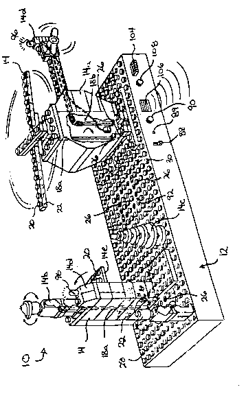
Reference is made to Figure 1 which shows a
construction toy 10 in accordance with a first embodiment
of the invention. The toy 10 includes a supporting base
21 76073
.
unit 12, a number of interconnectable plastic toy modules
14, and one or more elongated plastic drive shaft elements
18a and 18b which, as will be described hereafter, are used
to drive one or more of the toy modules 14 in movement.
Figure 1 shows best the toy modules 14 as being
of the type found in LEGOTM construction toys. The modules
14 are of a conventional known type and include block-like
modules 14a of differing widths and/or lengths, as well as
a smaller number of specialty modules 14b,14c,14d,14e which
simulate people, trees, lamps and other ChAp~s and
structures. Each of the modules 14 is characterized by a
surface having a number of uniformly spaced cylindrical
projections 20 and a surface having a number of
correspondingly shaped and sized cylindrical recesses 22.
As is known, the projections 20 and recesses 22 of the
block-like modules 14a are aligned in opposing parallel
surfaces to permit the modules 14a to be stacked together.
The recesses 22 are positioned in an identical spaced
arrangement to that of the projections 20, such that the
projections 20 of one module 14 may be inserted into the
recesses 22 of another, thereby releasably coupling the
modules 14 together in a snap fit.
It is to be appreciated that while Figure 1 shows
the construction toy 10 assembled to form a toy helicopter
and a toy castle, the arrangement of the projections 20 and
recesses 22 permit the toy modules 14 to be stacked in an
interconnected arrangement to form almost any fictional or
realistic toy structure, vehicle, machine, person and/or
animal, or the like.
The base unit 12 is provided as the support upon
which the modules 14 are assembled in erecting a toy, and
includes a number of movable cylindrical sockets 26 which,
as will be described hereafter, are used to actuate all or
2 1 7 6 0 7 3
- 13 -
part of the erected toy in movement.
The base unit 12 shown in Figure 1 includes a
generally planar mounting surface 28 which has a size
selected to permit at least eight modules 14 to be mounted
directly thereon. To enable the modules 14 to be mounted
on the base unit 12, the mounting surface 28 is provided
with a number of upwardly extending cylindrical projections
30 having the identical size and substantially the same
spacing as the module projections 20. In this manner, the
toy modules 14 may be releasably coupled to the mounting
surface 28 by the insertion of one or more of the
projections 30 into corresponding module recesses 22.
Figure 2 shows best a partially cut-away portion
of the base unit 12 which includes the right hand portion
of the mounting surface 28a prior to the erection of toy
modules 14 thereon. Mounting surface 28a has eight
rotatable sockets 26 provided therein at various spaced
locations. The sockets 26 are shown as located so as to
occupy the position which would otherwise be occupied by a
projection 30, but could equally be provided in other
spaced arrangements. Preferably each socket 26 is
rotatably provided centered within an associated circular
aperture 32 which extends through the mounting surface 28a.
The sockets 26 are flush with or slightly recessed into the
mounting surface 28 so as not to interfere with the
mounting of the toy modules 14 on the base unit 12. As
seen best in Figures 3 and 4, the sockets 26 open upwardly
to define an axially extending square recess having a size
selected to receive therein a lower end of a drive shaft
element 18a,18b, so that movement of the socket 26 rotates
a corresponding drive shaft element 18 which is inserted
therein in movement.
Figures 3 and 4 show best the linkage assembly
21 76073
which is used to rotatably couple the sockets 26 to an
electric motor 66, and which are each housed within the
base unit 12. Each of the sockets 26 extend upwardly from
the centre of an associated spur gear 40 which is rotatably
housed with the base unit 12. The spur gears 40 are formed
as flattened circular disks having toothed peripheral edges
41, and are positioned within the base unit 12 sandwiched
between the underside of the mounting surface 28a and a
horizontally extending divider panel 42 which is spaced
above the bottom 45 of the base unit 12. The spur gears 40
are provided in a substantially co-planar orientation and
are rotatably coupled to the divider panel 42 at locations
spaced radially about a circular opening 46 formed through
the panel 42.
A drive gear 50 is rotatably provided within the
base unit 12 for driving the spur gears 40 in rotation.
The drive gear 50 is rotatable on a central shaft 52 which
is rotatably secured to the bottom 45 and aligned with the
centre of the opening 46. The gear 50 includes an upper
circular portion 56 which projects upwardly through the
opening 46 and a lower enlarged circular portion 58 which
extends radially outward between the divider panel 42 and
bottom 45 of the base unit 12. The upper portion 56 of the
drive gear 50 includes a toothed peripheral edge 57 for
meshing engagement with the peripheral edge 41 of one or
more of the spur gears 40. The lower portion 58 of the
gear 50 includes a toothed radially extending lower rack 60
formed in the underside of the gear 50.
In the embodiment shown, four of the sockets 26a
in the mounting surface 28a rotate through 360 of movement,
two of the sockets 26b reciprocally rotate through
approximately 60 of movement; and the remaining two sockets
26c rotate reciprocally through approximately 60 movement
in an opposite direction to the direction of the sockets
21 76073
-- 15 --
26b.
The rotation of sockets 26a occurs by the direct
engagement of the peripheral edge 57 of the upper portion
56 of the drive gear with the peripheral edge 41 of each of
the associated spur gears 40a. As the drive gear 50
rotates, the engagement of the toothed edges 57,41 rotates
the spur gears 4Oa and sockets 26a in the opposite
direction. Sockets 26b are driven in reciprocal movement
by the sliding of the engagement of a camming roller and
pin 61 which projects upwardly from a peripheral upper
surface of the portion 56, within slots formed in rocker
arms 62a,62b which are attached to each of the respective
spur gears 40b. To minimize manufacturing costs, it is
preferable that sockets 26c be driven in rotation by the
engagement of the toothed peripheral edges 41 of the spur
gears 40b with the peripheral edge 41 of a corresponding
spur gear 40c. It is to be appreciated however that the
speed at which the sockets 26 rotate and the directions and
degrees of rotational movement may be easily varied by
adjusting the arrangement of the spur gears 40.
As seen best in Figures 3 and 4, the drive gear
50 is driven in rotational movement by the electric motor
66 which is powered by a battery 68, and a linkage arm 70.
The linkage arm 70 has provided at its end a pinion 72
which is configured to engage the lower rack 60.
A slip clutch 76 is provided to disengage the
pinion 72 from the motor 66 in the event too large a
resistive force is placed upon one of the sockets 26. The
clutch 76 consists of a driving member 78 which is coupled
to the motor drive shaft 80 and a driven member 82 provided
on the linkage arm 70. The driving member 78 and driven
member 82 are provided with complementary angled faces
79,83. The driven member 82 is slidable along the linkage
- 21 76073
-
- 16 -
arm 70 between a first position, wherein the angled faces
79 of the driving member 78 rotatably engage the angled
faces 83 of the driven member 82; and a second position,
where the driven member 82 is moved away from the driving
member 78 and the angled faces 79 rotate relative to the
faces 83.
The driven member 82 is coupled to the linkage
arm 70 such that the rotation of the driven member 82
rotates the linkage arm 70 and pinion 72, while permitting
sliding movement of the driven member 82 axially along the
linkage arm 70 between the first and second position. The
linkage arm 70 may therefore have a square cross-sectional
profile, as is shown in Figure 4.
A spring 86 is used to normally bias the driven
member 82 to the first position in contact with the driving
member 78. When a resistive load on the driven member 82
exceeds the critical load, the driving member 78 rotates
relative to the driven member 82. On movement of the
members 78,82 relative to each other, the sliding contact
of the angular surfaces 79,83 urges the driven member 82
against the bias of the spring 86 away from the driving
member 78 so that the driven member 82, linkage arm 70 and
pinion 72 are no longer rotated by the motor 66. On the
release of the resistive load forces, the spring 86 returns
the driven member 82 into engaging contact with the driving
member 78, whereby under either no load or normal load
conditions the rotation of the motor drive shaft 80 and
driving member 78 rotates driven member 82, linkage arm 70
and pinion 72, thereby rotating the drive gear 50.
The clutch 76 advantageously minimizes the risk
of damage to the base unit 12 of the toy 10. If excessive
resistant forces are applied to the drive gear 50, as for
example on a child grasping a drive shaft element 18 with
21 76073
sufficient force as to prevent its rotation, as well as the
associated socket 26 and the spur gear 40, the driving
member 78 will continue to rotate relative to the driven
member 82 and no excessive forces will be placed upon the
motor 66.- As the gears 40,50 are no longer rotated, the
risk of damage to gearing of the base unit 12 is also
eliminated. The foregoing construction is thereby
advantageous in that a small child may, when erecting a
construction toy, impede the movement of one or more
rotating sockets 26 without adversely harming the gears 40,
drive gear 50, linkage arm 70 or the motor 66.
As schematically illustrated in Figure 4,
electricity flow from the battery 68 is controlled by an
on/off switch 88, and current flow is indicated by a
"power-on" light 89 provided on the side of the base unit
12. A rheostatic speed control 90 is preferably also
provided, permitting the speed at which the motor 66 and
sockets 26 rotate to be varied, maximizing the adaptability
of the toy 10.
Figures 2 and 4 show best the base unit 12 as
further including a number of electrical receptacles 92
which are electrically connected to battery 68 and
controlled by switch 88. Figure 4 illustrates the
receptacles 92 as part of an electric circuit 98. Although
not shown, it is to be appreciated that the circuit 98
extends as a loop under the entire mounting surface 28 to
connect with the remaining receptacles 92. Like the
sockets 26, the electrical receptacles 92 are flush with or
recessed into the mounting surface 28 so as not to
interfere with the mounting of the toy modules 14 on the
base unit 12. The receptacles 92 are for use with light
units 96 which include male connectors 97 adapted for
removable insertion into a corresponding receptacle 92 and
which may, for example, be provided as part of a specialty
2 1 76073
- 18 -
module 14d.
Figures 3 and 4 show best electric circuit 98 as
including a spring contact switch 100 for providing
intermittent current flow to the receptacles 92. A number
of radially spaced camming projections 102 are provided
about the rotatable shaft 52 which extends below the drive
gear 50. As the gear 50 rotates, the camming projections
102 bias the spring contact switch lO0 to a closed position
which permits current flow to the receptacles 92. As each
projection 102 rotates past the contact switch lO0, the
switch lO0 resiliently returns to an unbiased, open
position which interrupts current flow. As such, on
rotation of the main drive gear 50, current is
intermittently provided to the electrical receptacles 92
with the result that connected light units 96 flash on and
off.
Figure 4 illustrates the light unit 96 having a
bulb, electrical cable, and plug, however, it is to be
appreciated that the light unit 96 could have any desired
shape, size and structure and could also be integrally
formed as part of clear plastic module provided with male
connectors for insertion into a receptacle.
The base unit 12 is preferably also provided with
removable sound card 104, speaker 106 and volume control
108 which provide an audio signal indicative of a
particular piece of equipment, vehicle or other toy which
is to be erected. The sound card 104 may be supplied as
part of a toy kit as to provide the sound effect which
corresponds to the toy package.
Figure 1 shows two drive shaft elements 18a,18b.
In the simplest construction, seen best in Figure 5, the
drive shaft element 18a is formed as an elongated plastic
2 1 7 6073
-- 19 --
member having a rectangular construction with the top end
36 having a square cross-section sized to fit into the
cylindrical recess 22 of a conventional module 14 in a
friction-fit. The bottom end 38 of the element 18b has a
square cross-section adapted for insertion into an
associated one of the sockets 26. The top and bottom ends
36,38 are sized to snugly fit in the respective recess 22
and socket 26, such that the rotation of the socket 26
rotates the element 18a together with the toy module 14
which is coupled thereto. It is to be appreciated that
both the bottom end 36 and socket 26 may also be provided
with either a non-polygonal or other polygonal cross-
sectional shape which minimizes the likelihood of the drive
shaft eIement 18 slipping in the socket 26.
While a drive shaft element 18a having the
simplified construction of Figure 5 is economical to
produce and may be provided in almost any length, it is to
be appreciated that drive shaft elements having a more
complex construction may also be used. Figures 6a and 6b
show other such drive shaft elements 18c,18b. The bottom
end 38 of the elements 18b,18c are essentially the same as
that as shown in Figure 5.
Figure 6b shows the top end 36 of the drive shaft
element 18c as being provided with an enlarged flattened
portion 110. The flattened portion 110 includes a number
of upwardly extending projections 112 as well as a number
of spaced sockets 114 which are the same configuration as
the toy module projections 20 and sockets 22. The
projections 112 and sockets 114 thereby releasably coupling
a toy module 14 to the top end of the shaft 18c.
Figure 6b shows the drive shaft element 18b as
being formed from two separate components 116,117 joined in
the middle and which each have the same structure as
21 76073
~,
- 20 -
element 18a. The top end 36 of component 116 has a square
or other polygonal cross-section. A flexible spring 118
connects the top and bottom components 116,117, permitting
the upper component 116 of the drive shaft element 18b to
be angled relative to the lower component 117.
While the base unit 12 is primarily adapted for
use with conventional toy modules 14, the applicant has
appreciated that by providing a smaller number of
customized modules 34,44,54,64 seen in Figures 7 to 11,
which interconnect with the conventional modules 14, a
construction toy 10 having even a greater degree of
flexibility and utility may be achieved.
Figures 5, 6b and 7 show two variations of
customized toy module 34 which may be used to conceal the
drive shaft element 18 within an assembled toy. Each of
the modules 34 are provided with a number of cylindrical
projections 120 which have an identical shape and size and
substantially the same spacing as projections 20.
Corresponding shaped recesses 122 are also provided with
the same size and spacing as the module recesses 22. The
toy module 34 shown in Figure 6b is provided with a
horizontally extending cylindrical bore 126 which is used
to conceal the horizontally oriented component 116 of drive
shaft element 18b.
In the module 34 shown best in Figures 5 and 7,
cylindrical bore 126 is provided in a vertical orientation
formed through the centre of the module 34. It is to be
appreciated that the bore 126 is sized having a radial
diameter selected to permit unhindered rotation of a drive
shaft element 18 which has been inserted therethrough. In
the manner shown in Figure 5 and 6b, the module 34 permits
the erection of a construction toy 26 so that the drive
shaft element 18 extends through the centre bore 126 formed
21 76073
.
- 21 -
in one or more stacked modules 34, and is thereby
completely concealed.
Figure 8 shows a modified use of the module 34
for linking together two rectangular drive shaft elements
18a,18a'. A removable cylindrical coupling sleeve 128 is
inserted into the bore 126. The coupling sleeve 128 is
rotatably seated in the bore by means of an upper
peripherally extending rim 130. Axially centered square
upper and lower recesses 132,134 are provided in each end
of the sleeve 128. The recesses 132,134 are sized to
receive an end of each respective drive shaft element
18a',18a in a friction fit, joining the two drive shaft
elements 18a',18a in rotational movement therewith.
Figure 9 shows another customized module 44 for
use with a drive shaft element 18a having a square cross-
section. Like the module 34, module 44 also includes a
number of cylindrical projections 120 and recesses 122
which are identical in shape and size to projections 20 and
recesses 22. The module 44 includes a square recess 140
which is formed in the centre of the lower surface of the
module 44. The recess 140 is sized to receive therein in
a complementary fit the square upper end 36 of a drive
shaft element 18a. By the use of module 44, the drive
shaft element 18 may be inserted into the recess 140,
whereby the rotation of the socket 26 rotates the module
44, and any modules 14 which are connected thereto.
Figure 10 shows yet another customized module 54.
In addition to projections 120 and recesses 122, the module
54 is provided with four internally meshing bevel gears
144,146,148,150. Each bevel gear 144,146,148,150 extends
as a shaft from the centre of the module 54, opening into
square shaped socket 154 which is sized to receive therein
an end of rectangular drive shaft elements 18a,18a'. In
21 76073
- 22 -
the manner shown, when the drive shaft element 18a is
inserted into the socket 154 of the bottom bevel gear 144
and the shaft element 18a' is rotated in the direction of
arrow 156, the drive shaft element 18a' which has been
inserted into the socket 154 of bevel gear 146 is rotated
in the direction of arrow 158.
Figure 10 illustrates a module 54 which
incorporates four bevel gears 144,146,148,150 ext~n~ing at
right angles to each other. Other combinations and/or
orientations of bevel gears are, however, also possible.
Similarly, while each of the gears 144,146,148,150 are
shown as extending outwardly to form a socket 154, one or
more of the gears 144,146,148,150 could also extend beyond
the module 54 and have an end adapted for rotatable
insertion within a socket 26.
Figure 11 shows an end view of a further
customized module 64 for use with the present invention.
The module 64 is identical to the module 14 with the
exception that a square recess 162 is formed in one end
surface 164 of the module 64. With the module 64, the
square end of a drive shaft element 18a may be inserted
into the square recess 162 to move the module 64 in
rotational movement about an axis parallel to its upper and
lower surfaces.
Figures 2 to 4 illustrate in detail one portion
of the mounting surface 28a together with rotatable sockets
26, spur gears 40 and drive gear 50. Although not shown,
it is to be appreciated that the sockets 26 which are
provided in the remainder of the mounting surface 28 are
driven in rotational movement by substantially identical
spur gear/drive gear 40,50 assemblies. The drive gears 50
of the remaining mounting surface areas may be rotatably
interconnected. Two or more sections or other mounting
21 76073
surfaces may be connected for rotation by a simple coupling
gear mech~n;sm, such as for example, by using a connecting
spur gear 172 positioned between drive gears, as is shown
in part in Figures 2 and 4. Alternately, the drive gear of
each separate section of the mounting surface 28 may be
driven independently by a separate motor and linkage
assembly.
Figure 1 shows a planar mounting surface under
which various separate gear/drive gear 40,50 assemblies are
provided. A single larger spur gear/drive gear 40,50
assembly could, however, also be provided under a mounting
surface which is provided with a number of distinct
mounting surface portions. The base unit 12 shown in
Figure 12 is provided with a number of generally horizontal
vertically displaced mounting surfaces 28a,28b,28c, but is
otherwise similar to the base unit 12 shown in Figure 1,
with like reference numerals identifying like components.
The mounting surfaces 28a-28c are illustrated as
being generally horizontal, with immediately adjacent
mounting surfaces 28 being vertically displaced relative to
each other. Figure 12 shows the base unit 12 as being
formed so as to simulate sloping terrain and is preferably
provided with colouring or other suitable indicia to
simulate hills, water or other geographical features. The
base unit 12 could, however, equally be formed to represent
part of a building, vehicle or other geographical area
and/or have one or more non-horizontal mounting surfaces 28
to which other suitable indicia are applied.
The spur gear/drive gear 40,50 shown in Figure 12
is substantially identical to that shown in Figures 3 and
4 with the exception that the sockets 26 extend upwardly at
different heights from the associated spur gears 40, into
a corresponding mounting surface area.
21 76073
Although it is advantageous that the rotatable
sockets 26 be recessed into the mounting surface 28 so as
not to interfere with the assembly of the various toy
modules 14 thereon, this is not essential. Further while
the preferred embodiment illustrates a mounting surface 28
having horizontally rotatable sockets 26, if desired,
additional sockets could be provided which are adapted for
vertical movement relative to the mounting surface.
Figure 1 illustrates the construction toy 10 as
incorporating a number of conventional block-like toy
modules 14a of the type found in LEGO toy systems, however,
the invention is not so limited. Other shapes and
structures of modules may equally be used, including
modules of the types found in MECCANO and K'NEX
construction toys, and will now become apparent. Figures
13a and 13b each show respectively two adaptor modules
174,176 for use with the present invention. The lower
surface of each adaptor module 174,176 is also provided
with a number of spaced cylindrical recesses (not shown)
for coupling the modules 174,176 to the base 12 on the
projections 30. Module 174 includes an upper ferrule or
178 configured for attaching MECCANO type modules
thereto. Module 176 is provided with a socket-type
connector 180 for use with K'NEX components. It is to be
appreciated that by the use of modules 174,176 and other
similar adaptor modules, the base 12 may be used with
almost any type construction toy.
While Figure 1 illustrates an assembled toy
incorporating a simple rigid drive shaft element 18a and a
flexible drive shaft element 18b, the multiple socket
arrangement advantageously permits the construction of toys
having a number of different types of movable drive shafts
and modules, and in which the modules are moved in
different directions and at different speeds.
21 76073
.
While the detailed description discloses
preferred embodiments of the invention, the invention is
not so limited and other modifications and variations will
now become apparent to persons skilled in this art. For a
definition of the invention, reference may be had to the
appended claims.