Sélection de la langue

Search

Sommaire du brevet 2176096 

Énoncé de désistement de responsabilité concernant l'information provenant de tiers

Une partie des informations de ce site Web a été fournie par des sources externes. Le gouvernement du Canada n'assume aucune responsabilité concernant la précision, l'actualité ou la fiabilité des informations fournies par les sources externes. Les utilisateurs qui désirent employer cette information devraient consulter directement la source des informations. Le contenu fourni par les sources externes n'est pas assujetti aux exigences sur les langues officielles, la protection des renseignements personnels et l'accessibilité.

Disponibilité de l'Abrégé et des Revendications

L'apparition de différences dans le texte et l'image des Revendications et de l'Abrégé dépend du moment auquel le document est publié. Les textes des Revendications et de l'Abrégé sont affichés :

  • lorsque la demande peut être examinée par le public;
  • lorsque le brevet est émis (délivrance).
(12) Brevet: (11) CA 2176096
(54) Titre français: METHODE ET APPAREIL POUR PLACER DU SABLE REFRACTAIRE DANS LE CANAL DE VIDANGE D'UN RECIPIENT METALLURGIQUE
(54) Titre anglais: METHOD AND APPARATUS FOR PLACING REFRACTORY SAND IN THE DISCHARGE CHANNEL OF A METALLURGICAL VESSEL
Statut: Périmé et au-delà du délai pour l’annulation
Données bibliographiques
Abrégés

Abrégé français

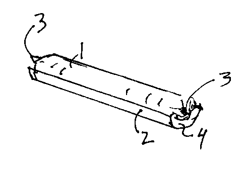
Cette invention concerne une méthode de garnissage en sable réfractaire du canal de coulée d'un creuset à vidange par le fond, méthode qui comprend l'orientation du creuset de manière que le canal de coulée se présente à l'horizontale, suivie de l'ouverture du canal. Une cartouche de sable réfractaire généralement cylindrique, fermée aux deux extrémités, est alors mis en place dans une chemise dimensionnée pour pouvoir glisser à l'intérieur du canal de coulée. Une fois la chemise garnie glissée en place, le canal de coulée est obturé et le creuset redressé.


Abrégé anglais


A method of placing a quantity of refractory sand in the
discharge channel of a bottom discharging metallurgical vessel
includes the steps of orienting the vessel whereby the channel
is presented in a horizontal direction, and opening the
channel. A generally cylindrical cartridge of refractory sand,
closed at both ends, is then loaded onto a casing dimensioned
to slide into the discharge channel. The casing with its
cartridge of sand is then slid into the channel, the channel
is closed and the vessel is righted.

Revendications

Note : Les revendications sont présentées dans la langue officielle dans laquelle elles ont été soumises.


THE EMBODIMENTS OF THE INVENTION IN WHICH AN EXCLUSIVE
PROPERTY OR PRIVILEGE IS CLAIMED ARE DEFINED AS FOLLOWS:
1. A cartridge for emplacement in the discharge channel of a
metallurgical vessel having a bottom discharge, including:
(a) a cylindrical bag of refractory sand;
(b) a casing dimensioned to fit fairly snugly within said
discharge channel, for loading said bag of sand into said
channel;
wherein at least one end of said casing is provided with a
radially inwardly directed flange.
2. A cartridge as claimed in claim 1, wherein said casing is
generally semi-cylindrical.
3. A cartridge as claimed in any one of claim 1, wherein said
bag is a plastic bag, sealed or secured at each end.
4. A cartridge as claimed in claim 1, wherein said refractory
sand has a grain size of 0.1 to 1.5 mm, and has approximately
the following composition:
Cr2O3 31-35%
Al2O3 9.5-11.5%
SiO2 26-30%
Fe2O3 18-22%
CaO 0.1-0.2%
MgO 5.5-7.5%
K2O 0.2-0.3%
Na2O 0.2-0.3%
C 0.4-0.6%

Description

Note : Les descriptions sont présentées dans la langue officielle dans laquelle elles ont été soumises.


217606
The present invention relates to the field of
metallurgical equipment, and in particular, to a method and
apparatus for introducing refractory sand into the discharge
channel of a vessel, especially a steel making ladle.
It is known to use refractory sand to fill the discharge
channel of a bottom slide ladle. This prevents molten steel
or other metal from solidifying in the discharge channel before
a tap, a condition that makes' it necessary to use an oxygen
lance to open the slide. This is a dangerous and time
1o consuming operation.
The ambient temperature in and over a ladle during
steelmaking operations is typically in the range of 1200°C -
1700°C. Therefore, it has heretofore been difficult to place
sand in the discharge channel of a ladle. This has
conventionally been done with the ladle upright, and the slide
closed to prevent the sand from escaping through the channel.
Then, one of three conventional methods has been attempted.
Often, bags of sand are tossed into the ladle at the channel.
This is wasteful, and does not assure that the slide will be
covered. Alternatively, a hopper can be lowered to a position
near the channel, and sand then released. However, manoeuvring
of the hopper is difficult in the high ambient temperatures,
and the operation is time consuming. Lastly, a funnel can be
used to deliver sand from near the lip of the ladle to the
-1-

CA 02176096 2001-03-08
channel. Again, this is a hazardous operation in the high
ambient heat, and it is time consuming.
One object of the present invention is to provide a method
of sanding the discharge channel of a metallurgical vessel,
during conditions of high heat.
Another object of the present invention is to provide a
cartridge containing refractory sand for insertion into the
discharge channel of a metallurgical vessel.
In a broad aspect, the present invention relates to a
cartridge for emplacement in the discharge channel of a
metallurgical vessel having a bottom discharge, including: (a)
a cylindrical bag of refractory sand; (b) a casing dimensioned
to fit fairly snugly within said discharge channel, for loading
said bag of sand into said channel; wherein at least one end of
said casing is provided with a radially inwardly directed flange.
-2-

CA 02176096 2001-03-08
In drawings that illustrate the present invention by way
of example:
Figures 1A and 1B are, respectively, diagrammatic
representations of the prior art methods of sanding the opening
channel of a metallurgical vessel, and the method of the
present invention;
Figure 2 is a perspective view of a sand cartridge of the
present invention;
Figure 3 is a perspective view of an insertion casing
according to the present invention; and
Figure 4 is a perspective view of a sand cartridge loaded
onto an insertion casing, for insertion into the discharge
channel of a metallurgical vessel.
Referring now to Figures lA and 1B, it will be observed
that according to prior methods, the discharge channel D of a
metallurgical vessel or ladle L is sanded from above, as
indicated by the arrow. The ladle L has traditionally been
sanded in the upright position, there having been no practical
method of sanding the channel with the ladle oriented
otherwise. The problem, however, with sanding from above,
either with bags, a hopper, or a funnel, is that the extreme
heat from the ladle prevents efficient work from being carried
-3-

217696
out in the space directly above the ladle. The methods
diagrammatically represented by Figures lA tend, therefore, to
be inefficient, time consuming and dangerous.
According to the present invention, however, the ladle is
laid on its side to have its discharge channel sanded, as _
presented by Figure 1B. It will be appreciated that a person
can approach the open discharge channel D of the ladle L and
efficiently insert a pre-measured cartridge, according to the
present invention. This operation is both safe and quick. In
this regard it will be understood that the ladle can be tilted
onto its side with no difficulty, using the equipment currently
in use in steel mills and the like.
In order to permit a sanding operation to be conducted
safely, according to the method of the present invention, there
is provided a refractory sand cartridge 1 (see Figure 2) and
an insertion casing 2 (see Figure 3). The sand cartridge 1 is
a diameter selected to slide easily into the discharge channel
of a metallurgical vessel, but to fit fairly snugly therein.
It is made from a flexible plastic tube, sealed or fastened
closed at each end 3, and filled with refractory sand. The
selection of a suitable refractory sand will be an obvious
matter of choice for one skilled in the art to which the
present invention pertains. However, an example of a suitable
formation for an acceptable refractory sand is as follows:
-4-

z ~ ~6e~~
Cr203 31-35%
A1203 9.5-11.5%
Si02 26-30%
Fe203 18-22%
Ca0 0.1-0.2%
Mg0 5.5-7.5% _
K20 0.2-0.3%
Na20 0.2-0.3%
C 0.4-0.6%
For such a sand, a grain size of 0.1 to 1.5 mm, and a
density of 2.05-2.15 kg/dm3 are appropriate.
In order to insert the sand cartridge into the discharge
channel of a hot ladle smoothly, the present invention provides
an insertion casing 2 (see Figures 3 and 4). The casing is
formed preferably as a longitudinal semi-cylindrical shell, one
end of which is provided with an inwardly directed lip or
flange 4. The shell holds a cartridge 1 of sand, and can be
slid easily into an open discharge channel. The lip 4 prevents
the cartridge from slipping during the insertion procedure,
which is conducted in conditions of very high ambient
temperature. The casing 2 is made from thin sheet steel, which
will melt on contact with molten steel, into the steel. The
refractory sand, on contact with molten steel, will solidify
into a plug, to isolate the ladle slide from the molten steel.
-5-

116096
The ladle slide may then be opened when desired, and the steel
will then flush out the plug, and flow out through the
discharge channel. When a pour is thus complete, the ladle
will be laid on its side, and a new cartridge inserted in the
discharge channel to again protect the slide from molten steel.
It will be understood that the casing 2, which is
illustrated as a semi-cylindrical shell, may extend over a
greater extend of a cylinder,'and may be a full cylinder, if
desired. The end of the casing 2 may be more closed than
provided for by flange 4, but the invention will function quite
well if no flange 4 at all is provided.
It is to be understood that the examples described above
are not meant to limit the scope of the present invention. It
is expected that numerous variants will be obvious to the
person skilled in the field of the present invention without
any departure from the spirit of the invention. The appended
claims, properly construed, form the only limitation upon the
scope of the invention.
-6-

Dessin représentatif
Une figure unique qui représente un dessin illustrant l'invention.
États administratifs

2024-08-01 : Dans le cadre de la transition vers les Brevets de nouvelle génération (BNG), la base de données sur les brevets canadiens (BDBC) contient désormais un Historique d'événement plus détaillé, qui reproduit le Journal des événements de notre nouvelle solution interne.

Veuillez noter que les événements débutant par « Inactive : » se réfèrent à des événements qui ne sont plus utilisés dans notre nouvelle solution interne.

Pour une meilleure compréhension de l'état de la demande ou brevet qui figure sur cette page, la rubrique Mise en garde , et les descriptions de Brevet , Historique d'événement , Taxes périodiques et Historique des paiements devraient être consultées.

Historique d'événement

Description Date
Le délai pour l'annulation est expiré 2011-05-09
Inactive : Demande ad hoc documentée 2010-11-04
Lettre envoyée 2010-05-10
Inactive : TME en retard traitée 2008-05-08
Inactive : Demande ad hoc documentée 2007-07-18
Lettre envoyée 2007-05-08
Accordé par délivrance 2002-01-22
Inactive : Page couverture publiée 2002-01-21
Inactive : Grandeur de l'entité changée 2001-11-15
Préoctroi 2001-10-31
Inactive : Taxe finale reçue 2001-10-31
Un avis d'acceptation est envoyé 2001-05-02
Lettre envoyée 2001-05-02
Inactive : Approuvée aux fins d'acceptation (AFA) 2001-04-18
Modification reçue - modification volontaire 2001-03-08
Inactive : Dem. de l'examinateur par.30(2) Règles 2000-09-11
Inactive : CIB en 1re position 2000-09-05
Inactive : CIB enlevée 2000-09-05
Inactive : CIB attribuée 2000-09-05
Inactive : Renseign. sur l'état - Complets dès date d'ent. journ. 1998-03-13
Lettre envoyée 1998-03-13
Inactive : Dem. traitée sur TS dès date d'ent. journal 1998-03-13
Toutes les exigences pour l'examen - jugée conforme 1997-12-03
Exigences pour une requête d'examen - jugée conforme 1997-12-03
Demande publiée (accessible au public) 1997-11-09

Historique d'abandonnement

Il n'y a pas d'historique d'abandonnement

Taxes périodiques

Le dernier paiement a été reçu le 2001-05-07

Avis : Si le paiement en totalité n'a pas été reçu au plus tard à la date indiquée, une taxe supplémentaire peut être imposée, soit une des taxes suivantes :

  • taxe de rétablissement ;
  • taxe pour paiement en souffrance ; ou
  • taxe additionnelle pour le renversement d'une péremption réputée.

Les taxes sur les brevets sont ajustées au 1er janvier de chaque année. Les montants ci-dessus sont les montants actuels s'ils sont reçus au plus tard le 31 décembre de l'année en cours.
Veuillez vous référer à la page web des taxes sur les brevets de l'OPIC pour voir tous les montants actuels des taxes.

Historique des taxes

Type de taxes Anniversaire Échéance Date payée
Requête d'examen - petite 1997-12-03
TM (demande, 2e anniv.) - petite 02 1998-05-08 1998-05-07
TM (demande, 3e anniv.) - petite 03 1999-05-10 1999-05-06
TM (demande, 4e anniv.) - petite 04 2000-05-08 2000-05-08
TM (demande, 5e anniv.) - petite 05 2001-05-08 2001-05-07
Taxe finale - générale 2001-10-31
TM (brevet, 6e anniv.) - générale 2002-05-08 2002-05-07
TM (brevet, 7e anniv.) - générale 2003-05-08 2003-04-24
TM (brevet, 8e anniv.) - générale 2004-05-10 2004-05-07
TM (brevet, 9e anniv.) - générale 2005-05-09 2005-05-04
TM (brevet, 10e anniv.) - générale 2006-05-08 2006-05-05
Annulation de la péremption réputée 2007-05-08 2008-05-08
TM (brevet, 11e anniv.) - générale 2007-05-08 2008-05-08
TM (brevet, 12e anniv.) - générale 2008-05-08 2008-05-08
TM (brevet, 13e anniv.) - générale 2009-05-08 2009-05-07
Titulaires au dossier

Les titulaires actuels et antérieures au dossier sont affichés en ordre alphabétique.

Titulaires actuels au dossier
FERROPUR INC.
Titulaires antérieures au dossier
JUERGEN WEBER
Les propriétaires antérieurs qui ne figurent pas dans la liste des « Propriétaires au dossier » apparaîtront dans d'autres documents au dossier.
Documents

Pour visionner les fichiers sélectionnés, entrer le code reCAPTCHA :


Pour visualiser une image, cliquer sur un lien dans la colonne description du document. Pour télécharger l'image (les images), cliquer l'une ou plusieurs cases à cocher dans la première colonne et ensuite cliquer sur le bouton "Télécharger sélection en format PDF (archive Zip)" ou le bouton "Télécharger sélection (en un fichier PDF fusionné)".

Liste des documents de brevet publiés et non publiés sur la BDBC .

Si vous avez des difficultés à accéder au contenu, veuillez communiquer avec le Centre de services à la clientèle au 1-866-997-1936, ou envoyer un courriel au Centre de service à la clientèle de l'OPIC.


Description du
Document 
Date
(aaaa-mm-jj) 
Nombre de pages   Taille de l'image (Ko) 
Revendications 1998-04-02 3 69
Abrégé 1996-08-18 1 16
Description 1996-08-18 6 196
Revendications 1996-08-18 3 63
Dessins 1996-08-18 1 15
Dessin représentatif 2001-12-17 1 5
Description 2001-03-07 6 188
Revendications 2001-03-07 1 28
Dessin représentatif 1997-12-03 1 1
Accusé de réception de la requête d'examen 1998-03-12 1 179
Rappel de taxe de maintien due 1998-01-20 1 111
Avis du commissaire - Demande jugée acceptable 2001-05-01 1 164
Avis concernant la taxe de maintien 2007-06-18 1 173
Quittance d'un paiement en retard 2008-05-19 1 165
Avis concernant la taxe de maintien 2010-06-20 1 170
Taxes 2003-04-23 1 37
Taxes 2002-05-06 1 40
Correspondance 2001-10-30 1 40
Taxes 2001-05-06 1 36
Taxes 1998-05-06 1 44
Taxes 1999-05-05 1 38
Taxes 2000-05-07 1 33
Taxes 2004-05-06 1 36
Taxes 2005-05-03 1 31
Taxes 2006-05-04 1 39
Correspondance 2007-07-22 2 222
Taxes 2008-05-07 1 58
Taxes 2008-05-07 1 56
Taxes 2009-05-06 1 51
Correspondance 2010-11-09 2 247